|
|
Maintaining Johnson 1980 - 1991 , (Information & Observations) |
|
, Evinrude, OMC, outboard motor, outboard motor repair, 9.9, 15 hp, date/year of manufacture, water pump, carburetor, long shaft, 15 hp conversion, sailmaster
|
|
Maintaining Johnson 1980 - 1991 , (Information & Observations) |
|
The photo above on the left is a 1984 with the one on the right being a 1988 model.
One thing that I want to convey here is that I write only on motors that I have actually worked on, and over a period of MANY years, consisting of many THOUSANDS of hours, and then more in maintaining/updating these articles. They are motor specific, HOWEVER if you are having a diagnosis issue, my Trouble Shooting article covers MANY more aspects that may help you diagnose your issue. CLICK HERE for access to that article.
There seems to be a gap in production of the 6hp motors from 1979 until 1984. However there was a 7.5hp made from 1980-1983 which utilized this newer exhaust housing/lower unit, and the twist throttle unit used the cable type with a kill button on the throttle end as found on these later models . Essentially the 7.5hp 1980-1983 motor was utilized as the basis for the newer 6 and 8hp motors where they just detuned the 7.5 for the newer 6hp. So any information of these 6 and 8hp motors would generally apply to those limited years of production 7.5hp motors.
| Here you see the 7.5 hp | |
 |
And one known 1983 6hp
Johnson made in Belgium that was actually a 7.5hp with a restrictor plate
between carburetor and the manifold. So it appears that you may also encounter some
hybrids in this 1980-1983 era.
In 1984 (at least in the US) they came back out with a 6hp and also upped the 7 1/2 hp designation to an 8hp. Now somewhere in the mix, I have seen a 1983 8hp, which does not show on any of the lists, so possibly it was a LATE LATE 83, but with the 8hp parts of a 84. The only difference was that it was painted all white as compared to the gray lower sections of all the known 84s .
1992 saw another major change in the 6 and 8hp motors with a completely different rope starter unit that mounted over the flywheel.
Also there was a 5hp in this series,
CLICK HERE which consisted of
basically a 6hp. This motor is a more economical one, not having a
shifting gearbox, meaning the motor is always in forward gear. It also
does not have a twist grip throttle, but a tall throttle lever on the Port side.
What sets it apart from many others in that HP class is that It
also does use the remote fuel tank.
General Observances : These motors only had the HP rating visible on the REAR of the upper cowling (other than on the ID plate).
The factory did however retain the spindle spool starter system of the 66 -79 for these 1984-1991 models. These newer models are not crowded under the cowling and have lots of room there.
The only difference in the 6 and 8hp of these years appears to be the carburetor, intake manifold, reed valve plate assembly and the front part of the block to accommodate the larger reed valve unit on the 87 and newer motors.
This being the case the I am not sure until I can tear both apart, but it may be that the carburetor will just have a larger main-jet. However on tearing apart the 6hp for a re-ring job the inlet hole in the manifold was considerably smaller than it could have been, like .625" (and could have gone at least to .800"). OK, I now found that the 8hp has a 1" inlet hole in the manifold and a larger throat in the carb with a #36 mainjet.
They
utilize the familiar slightly angled cowling/lower pan joint used by the 9.9/15hp motors of the
same years. The 1984 model that I have has the whole lower section including the
cowling pan painted gray, with the top fiberglass cowling painted ivory.
All the informational decals for this gray model until 1988 use white lettering.
There
appears to be no provision for electric start on these motors.
However the later ones after 1988 were possible to have a 12volt charging system
on them. These motors came
standard with the 15" shaft length, but could be had in a long 20" or even 25"
extra long shaft for sailboats.
They do
have the thermostat on the upper rear of the head, held in by 3 bolts which is readily
accessible at the top rear of the head. This cover is made of plastic.
I personally like the gray bottom paint (used from 1984 to 1987) as it hides the scuff marks and oil you normally get on these motors that are used as a fishing motor. These are not a show motor, but a working motor.
I also find that this series of motors are pretty well bullet-proof as most of the bugs that may have been encountered on the previous model have been eliminated, as like now using the cable throttle system, the electronic ignition works well and they were made before a lot of plastic was introduced in the manufacture of them (and were less prone to break). And they are rather simple, functional with no frills.
These motors, like many series also
underwent minor changes during their production, like carburetors and ignition.
In the LH photo below you will see the front view of a 1984 6hp Johnson.
Note the "Slow Speed Adjustment" "Lean / Rich" knob at the center top
of the front panel.
This knob is the carburetor idle adjustment knob. Obviously the handle on
the right operates the manual rope starter and the knob on the left is the choke. The
two pronged coupler on the lower right is the fuel line connector. The knob at the lower
left on the transom mount is for the tilt lock.
| Here is the front view of a 1984 6hp | Here the rear HP designation |
 |
|
Year of Manufacture : This is important in any repair, for obvious reasons. Prior to 1979, Johnson used the last 2 digits of the year in the model number. Here is a LINK to help you determine any of the Johnsons. And here is the LINK for the Evinrudes. For those of you readers outside of the United States, here is another LINK that may better help with your motors.
After 1979, OMC's
manufacturing year code, which included Evinrude, is the word "INTRODUCES",
with each letter
equating to a number ie:
I=1,
N=2,
T=3,
R=4,
etc. as illustrated below.
As before, the last 3 letters are what you are looking
for. Then in this case, disregard the last one, as it pertains only to a model
revision that only on specific cases may be revalent to a marine repairman if
problems arise. A code of
J6RCRM
would equate to Johnson,
6hp,
R rope start,15"
(short shaft as no code letter here),
CR
= 1984,
and
the M
could be a model revision, so this motor would probably be made in the later part of
the year. You may encounter a code of something similar to
J6RLCRM.
This L would
have long a 20" long shaft. For more detailed
information on worldwide production,
CLICK HERE
|
DATE CODE |
I |
N |
T |
R |
O |
D |
U |
C |
E |
S |
|
|
1 |
2 |
3 |
4 |
5 |
6 |
7 |
8 |
9 |
0 |
Using
this code system, if the motor was sold as an Evinrude, then the first letter would have
been an E
instead of the J
for Johnson.
Then you can encounter motors made in or for other countries, which will have
some added letters as mentioned later in this article.
There should be the model and serial number on riveted on 1” X 2” aluminum ID plate on the LH side of the transom mount bracket (looking forward). Sometimes this ID plate can get removed. If this happens, you can still usually tell which motor it is by looking at the 25 cent size soft plug in the upper rear RH side of the block. The model and year are stamped in this soft plug also but probably only up to 1979. It is interesting to also note that the 6 hp uses the same block as the 8hp, so you could see either hp with the same 6R78M numbers here as the 8hp has. You may find that the plug numbers do not match any of the codes, as the factory changed things as time went on.
Exploded Parts
Lists :
For a
internet link to a marine parts seller
CLICK HERE
that has exploded views as shown below in this article. From
this business, you can identify the numbered parts ad purchase parts online from
them.
Flywheel :
To get to the electronic
ignition which are under the flywheel, you will need to pull the flywheel off
the tapered shaft of the crankshaft. Removal of this nut needs a 3/4"
wrench. If it is so tight that you can not loosen it normally, then try to
tap the wrench with a medium hammer to jar the nut loose initially. If
that does not work then you will have to resort to a air impact gun.
Most times if you just
loosen the flywheel nut a few threads, (leaving it about even or slightly above the shaft's
threads) then hold onto the flywheel by wrapping your arm around it and lift up enough
to put a lot of upward strain on (almost holding the motor upright) then rap the nut HARD
with a HEAVY brass mallet, the flywheel should pop off the crankshaft taper.
The reason for the brass hammer is so it does not damage the nut or shaft
threads as much. You could get by with a regular hammer if you are careful. One
hard rap is better than a dozen love taps.
If this does not pop
the flywheel loose, then you will have to resort to a flywheel puller as shown
in use below. In using these, you remove the flywheel nut first. These usually have 4 slots milled in the top flange to
accommodate the bolts to be threaded into corresponding threaded holes in the
top of the flywheel. Here we will be using only 3 that are spaced evenly.
This puller could be also use if only 2 opposing holes were there. The
large bolt in top is threaded into the puller boss. In use you thread the
3 smaller bolts into the flywheel so that they will allow the puller to set
evenly on top. You then tighten the large bolt into the puller, which puts
pressure on the crankshaft end, pulling the flywheel up. If it comes
really tight, then with the large bolt's pressure on the crankshaft, rap the
large bolt head with a hammer as before, which usually will help and pop it
loose.
This
flywheel is located in the proper position on the
crankshaft by a 1/2 round woodruff key. This proper position is critical
as to the timing when the CDI ignition spark fires the spark plugs.
If this key gets damaged or partly sheared, the motor will not run well, if even
start.
| Home made flywheel puller in position on a 6 or 8hp |
|
|
If you have to work on the rope starter of these motors,
this flywheel is easier to remove than trying to jockey the starter removal
around under it.
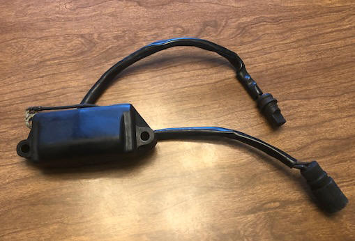
Electronics : And these newer motors all used the newer Capacitor Discharge Ignition (CDI) system that uses a power pack as shown in the photo below on the left. They (the power packs) have a code, like CD 2 which designates a 2 cylinder, or CD 3, for a 3 cylinder, etc. There appear to be two different power packs used, one for the 6hp and another for the 8hp. The differences are the 6hp is a standard unit, while the 8hp has a built in Rev Limiter of 5,800 RPM. And at a OMC price of $82 for the non as compared to $161 for the Rev Limiter version. Sierra makes a cheaper ($64) for the 6hp however. The reason in my mind for the difference is that the 8hp more than likely (if a long shaft) could be used on a sailboat. It also has a slightly larger carb venturi throat opening and a larger manifold opening, where it is possible to get more RPM, and may over rev.
There are wires coming out, and two rubber electrical connectors from the power pack, both with internal pins, one for the coils, and the other for the electronics under the flywheel timing plate assembly, as seen in the RH photo below. Here the timing plate consists of the plate, pickup coil (white), and charge coil (black), with the wires leading out.
From observing the parts list, these motors from 1989 on, came set up with a UFI (Under Flywheel Ignition) eliminating the external power pack. Here, the power pack was incorporated into the timing plate assembly.
They also could have had a AC or DC electrical outlet. The AC would have been for sale in Europe, while the 12 volt DC by being run thru a regular rectifier for battery charging in the US. There however were no provisions for a electric starter.
| CD 2 Power Pack. Here the bottom wires/plug mate into the timing plate plug seen on the right | Timing plate with electronic coil & pickup sensor for a prior to 1989 motor |
 |
 |
Powerhead : The photos below give you a visual idea of what the powerhead looks like under the cowling. You will notice in the LH photo, that it retains the spool type starter system and has the electronic ignition coil/power pack. In the RH photo the cable that comes from under the carburetor and over the block behind the flywheel is the throttle cable that is attached to the timing plate arm as seen in the LH photo. And the thermostat is on the top of the head. The carburetor is under the black plastic breather box.
| 6 / 8hp powerhead viewed from LH side | 6 / 8hp powerhead viewed from RH side |
|
|
|
Internal Engine Parts : This engine has a bore and stroke of 1.9375 ' x 1.700" and the ring width of.0625", with a displacement of 10 Cubic Inches. Both the top and bottom main bearings are caged ball bearings, while the center main bearing and the connecting rod bearings are non-caged needle bearings riding in a stainless steel liner. These loose needle bearings are not interchangeable as the center main bearing is larger than the rod bearings.
Coils :
The coils (one for each cylinder) are mounted on the rear
RH part of the block as seen in the RH photo above. The top coil is for
the top/number 1 cylinder, however they are not identified, except usually the
top spark plug wire will have a white plastic strap around it identifying the
recommended spark plug. If on reassembly and you did not mark the top one,
and you got them mixed, if it does not start, just swap the plug wires to see if
it will start, if so then remove the coils and reposition them so the top coil
fires the top spark plug.
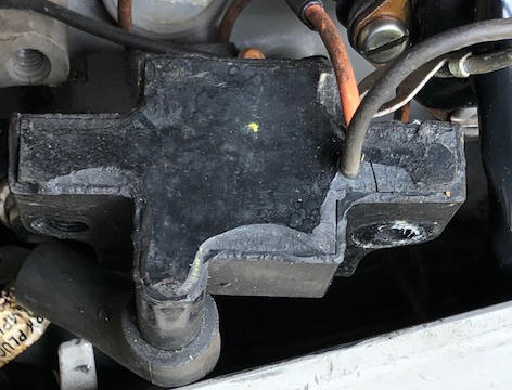
On my motor, I
found the inner part of the coil was separating from the outer hard shell. My thinking
was that with this separation, it may have a chance to have moisture enter and
cause problems later on (but the damage had already been done). So, I found some black caulking and
re-sealed these gaps. This gained me a few years before one died. In the
LH photo below, the top coil was unbolted from
the block, allowing it to be better positioned for this photo.
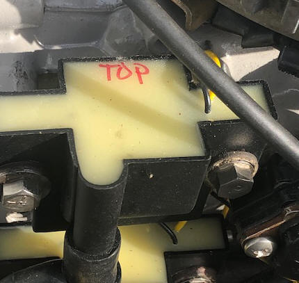
| Here, you can see the separation, with the softer potting being cut away for better adhesion of the new caulking | Here are new coils, each having a black (ground) & a yellow wire from the power pack |
 |
 |
Spark Plugs :
Spark plugs for these motors need to be 14mm threads with a
1/2" reach. They
REQUIRE this thread length at 1/2".
By this the 1/2" reach is measured from the base of the
threads to the end of the electrode and you will probably only have 3/8" of
threads. They will have a 13/16"hex body.
The plugs recommended here will fit the right "reach"
length. If you try to put anything longer in, they will reach
too far and possibly hit the top of the piston, doing damage.
Most of the OMC
models, at least from 1983
will have the tape in the spark plug wire recommending Champion L77J4 plug which would be the corresponding conventional single electrode Champion plug. You now may have to use L77JC4,
or it's newer replacement #821 or the #821M for marine use. If you can't
get the "M" series, don't worry, as it is probably just the
outer metal coating that may be more resistant to salt air. If you are using the motor to run to the fishing area and stop to fish or troll
slowly for extended periods of time, these plugs are probably the better choice
as they tend to not foul as bad as the air gap plugs do. So, use the above
information as to your usage to determine the plug you need, NOT necessarily the
recommended one on the motor.
You may find a recommended plug of QL77J4,
this is the same plug as above but with a resistor or sometimes called a radio
noise suppressor plug. this one would be recommended of you are running a sonar/depthfinder
or VHF radio.
Fuel Pump :
These fuel pumps are pretty
universal, the same small square one fitting most all these small motors
up to 40 hp until about 1987. They were bolted onto the side
of the block with 2 screws and the center hole was the suction/vacuum
source into the crankcase. Since these motors used only a rope
starter, the standard fuel pumps would be the small square version up
until the 1987 transition. For a link to the rebuild procedure for this
older small square fuel pump
CLICK HERE.
You will
notice that all the fuel pump screws are slotted instead of being the
newer Philips X slots. One thing that I do when I get into a
repair is to remove the two that hold it to the block (front and rear),
and replace those two with Phillips. This gives a novice some
reference as to which to remove when removing the fuel pump and to not
remove the wrong ones which are what hold the pump body together.
| Here is the early style fuel pump nestled in front of the coils |
|
|
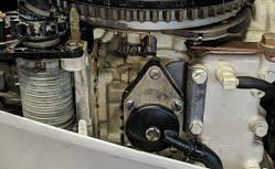
The 1987 factory parts lists show "early" fuel pumps and "late" fuel pumps. It appears that this "late style" was ONLY used the last part of 1987 through 1990 (as seen in the photo below) which shows the late larger fuel pump mounted of the left side of the motor using a tube connected around the rear and under the block from the original fuel pump mounting location on the right side. For a link to the later larger fuel pump that came into being about mid 1987 CLICK HERE.
| Here is the later large style fuel pump |
 |
Fuel Filter :
These series of motors utilized a filter screen on
the intake of the fuel pump. This pump also included a fuel filter
screen, as seen in the photos above, the black plastic inlet is secured by a
single center screw. By removing this screw, this fuel inlet cover
can be removed, UNDER and pressed into the underside is a fine stainless
steel filter screen. Also is a Neoprene gasket just the shape of
this cover. For the early pumps, the cover and gasket have 4 scallops corresponding to
the 4 fuel pump bolts of the early square pumps. If this fuel inlet needs to be rotated for
better fuel line alignment, it can be rotated 4 different 90 degree
locations. The later fuel pump uses a round plastic inlet, so they
can be rotated anywhere within reason.
If you suspect a fuel problem, you can check the
fuel pump by being able to suck, but not blow into the outlet, blow but not suck
out of the inlet.
For you owners of 1987
motors, you will have to look at your own individual fuel pump to decide which
it is, as I do not have data relating to serial numbers and collation of
which was used during the transition era, but from the photo above the
large center screw holding the fuel pump cover on, under it will be a filter
screen.
These motors use the single fuel line and the standard OMC quick fuel line couplers.
FYI : Now, just because this filter on the fuel pump is in the system, does not mean it is a cure all. Yes it is a somewhat smallish screen, but fine debris could pass through. I have seen motors that would idle like a dream, but starve out when revved up, even after numerous carburetor cleanings. These repeated cleanings revealed a black powder like residue, that had even become caked in places, even inside the primer unit. What I finally found was that apparently these motors had been using Ethanol Gasoline, and not ran dry at the end of the day, which ate away some of the rubber inside the fuel lines both to the fuel pump and after it. The only way to get rid of that was to clean everything and replace all the fuel lines and flush the fuel pump. I do however, hesitate to tear into any fuel pump apart if they were operational because of the complexities of combined small parts.
Carburetor :
For those of you unfamiliar with small outboard
motor repair, to remove this carburetor for the older metal topped carbs, unscrew the three top bolts holding
down the top plastic silencer/breather cover (29) in the illustration below.
The "Rich/Lean" idle knob can be pulled straight forward and off it's splined
shaft. Make a mental picture of which way the indicator
pointer is pointing so you can re-install it the same.
Then unscrew the retainer screw holding on the choke knob
(outside front of panel) and remove this knob. The rear of this
plastic choke rod connects to the carburetor choke arm by a small headed pin
that uses a O-Ring as a retainer.
On some motors you may find the pin's head either on the outside of the
connector or inside. Others may have a #6 bolt and Nylock nut (probably an
aftermarket). Remove this pin,
or screw. Now you can
withdraw the choke rod rearward and through it's hole in the lower plastic
carburetor breather body
(#28). From there, the lower breather body can be lifted up and away
from the carburetor by finding the right twisting location.
Take notice of this rectangular choke rod when you withdraw
it, as on the top centerish of the rod, you will find a shallow upward Vee
There should also be a foam rubber seal (#26) that may be
sticking the breather to the carburetor, if so, a bit of wriggling of the
breather body should dislodge it.
To remove the carburetor from these motors, you will need to remove the breather box cover, and depending on the carburetor (3 screws) then 2 more screws that hold the bottom of the box to the top of the carburetor. Also the choke rod or primer rod needs to be removed. The choke is accomplished by first removing the small Neoprene O-Ring that acts as a retainer on the outer end of the choke retainer pin. Pull the pin and then push the rod in and remove it from the rear of the front panel. The primer type requires removal of a small screw that connects the primer from the pull rod.
Also the starter spool will have to be
partially removed in order to access the Port side carb retainer nut. Remove
the two top bolts (using a 5/16" box wrench) from the recoil starter spool
mounting plate. Very carefully pull the complete starter to one side,
BUT just so far that do not pull the recoil spring out of the base.
You have to remove the starter to access the LH carburetor mounting nut and
remove that nut. Tip it forward to give clearance for the carburetor retainer nut
(#33) (1/4" SAE nuts), one on each side .
Remove the carb cam roller pivot screw #4 and rotate the roller unit off the
linkage rod.
Remove the RH carburetor nut, slide the carburetor
forward off mounting studs and then remove the inlet fuel line.
The carburetors used on these motors varied with the year of manufacture. The early metal top ones (1984-1985 are rather simple units and quite reliable with a fixed main jet, otherwise called the "High Speed Orifice Plug" #24. The hole size for the 6hp is #35 and for the 8hp is #36 (not much of a difference). These numbers relate to drill bit sizes. These early models have a metal bottom float bowl, while the later ones can have a plastic bowl.
You can then remove the bottom bowl,
the float pivot shaft and lift off the float assembly which includes the
inlet needle. Place all parts so you can easily identify them for
reassembly. You can then unscrew the brass main jet and or idle jets.
If you have the older metal topped carburetor, it may be best not to even
try to remove the slotted inner brass idle tube.
The slow speed idle jet screw (#15 in the
illustration below) has many small spline serrations on the outer end that mate
with splines in the hard rubber knob. The placement of this knob on the
front cowling makes for only 180 degrees of rotation. In doing any fine
adjustments after final assembly on the motor, if you can not get the knob to
rotate as far one way or the other to get a smooth idle, pull the knob straight
forward and off the shaft, rotate it 180 degrees so you get a better chance to
tune the motor. Then once I get this "sweet spot", I like to pull it
off again and position the pointer on the knob straight down, this gives me s
then known return position and about 90 degrees of movement either way if my
fuel ratio changes.
The normal number of turns out from lightly bottomed out for the low speed (idle jet) #15 is 1 1/2 turns as a start setting. My motor likes 1 1/4 turns out.
| Shown below is the carburetor & breather for a 1984 & 1985 |
 |
|
1985 metal top carburetor with butterfly choke & metal fuel bowl |
|
|
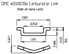
Shown below is the carburetor link for the older all metal carbs. Dimensions are fairly critical for correct carb/electrical timing. The Vee bend usually points forward to give clearance. I suspect these are made from existing links off other motors, and the bend was a simple method used to facilitate inventory. If I had to make a new one, it would be the dimensions given here, but no bend. These sell for only $30.00, so when the arm breaks, this link may disappear also.
| Here is a 1984 - 1989 carburetor link |
 |
The later carburetors used a plastic top. The early with these plastic tops still utilized the front mounted idle mixture screw. Then about 1988 or so this screw hole was plugged and a rear starboard side adjustment screw was used. These plastic topped ones used a internal box like collector that the main-jet was screwed into. This system appears to help by separating to some degree any small debris from being sucked into the main-jet.
| The late intermediate style plastic top carburetor with side idle adjustment and primer unit (note no choke). These also used a plastic bottom fuel bowl. |
 |
You may see different configurations of these plastic topped carburetors. The bottom metal sections will be the same, but tops can vary. Some of the early ones can have the needle inserted in place of the #33 plug screw as seen in the illustration above. These will not have the threaded hole at the RH rear where again in the illustration above #15 idle needle as seen in the LH photo below.
Note in the photo below that the
idle adjustment screw is moved to the rear side and the front hole is
plugged plus that it has no choke as it uses the fuel primer system as
indicated by the lower fuel line fitting which is the inlet for a
choke/fuel primer as mentioned below.
| Here is a 1989 8hp carburetor using the fuel primer | |
|
|
You may encounter a carburetor that has no
rear idle needle, and the adjustment needle is on the front of the plastic
top, pretty much as seen in the photo above. If this is the case to
adjust the idle, it may be best to drill a 3/8" hole in the front cover and
align it with that needle screw head so you can adjust it while running.
However you need to remove the air breather box. This cover is a
later conversion unit # 036342.
On my 1984 6hp the inner (rear) carburetor
throat diameter is .810" with the mating hole in the intake manifold
being only .612". This hole in the manifold is not cast but machined
not true with the carburetor's mating hole, but slightly lower by about 1/8"
or the top of the hole even with the top of the carb mounting studs.
The inner throat is .625" and the outlet at .800".
Measurements off a 8hp inner throat is .650" with the manifold diameter
entrance hole being larger, which is 1.00" and the mainjet #36.
In re-assembling any carburetor, IF it has a metal tag under one of the bowl screws, remember to put this back as the numbers on this tag may be critical if you ever need a repair kit.
Air breather or air box as they are usually called by the manufacturer on this motor is rather unique in that this motor appears to be somewhat semi-super charged. By this, I mean the actual breather intake is mounted very close to the flywheel ring gear starter teeth. In operation the rotation of the flywheel forces air from these teeth into the carburetor air box.
On these plastic topped carburetors, there is
a slow speed stop adjustment screw (#31 in the illustration above) on the
port side about the middle. This just screw just adjusts the throttle
shaft butterfly as a low speed setting. It does not fine tune the idle
jet (#15 in the illustration above) which is either on the center front of
the plastic top or on the rear starboard side (depending on the year of
manufacture). You may have to adjust each individually, but in
synchronization to get a good low trolling speed.
Now IF you misplaced the two attaching screws for the
plastic silencer/breather cover, they are #10 X 24 X 3/4" long with flat
washers.
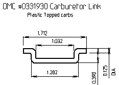
Shown below is the carburetor link for the plastic topped carbs. These only sell for $30.00, so when the arm breaks, this link may disappear also.
| Here is a 1988 - 1990 carburetor link |
 |
Choke / Fuel Primer :
These motors used 2
types of choking systems. The 1984 and 1985 used the conventional
butterfly choke. 1986 thru 1989 used a combo choke/fuel primer system.
They reverted back to the conventional choke system in 1990,
WHY ?
A guess is that when
these primer chokes work, everything is fine, but as they age, weird things start
happening and if there is any fuel contamination, this is a logical location
for it to collect. Actually it was not a
choke as we know it, but merely a system that injects a small amount of
atomized fuel
directly into the carburetor throat, or intake manifold (depending on the
model).
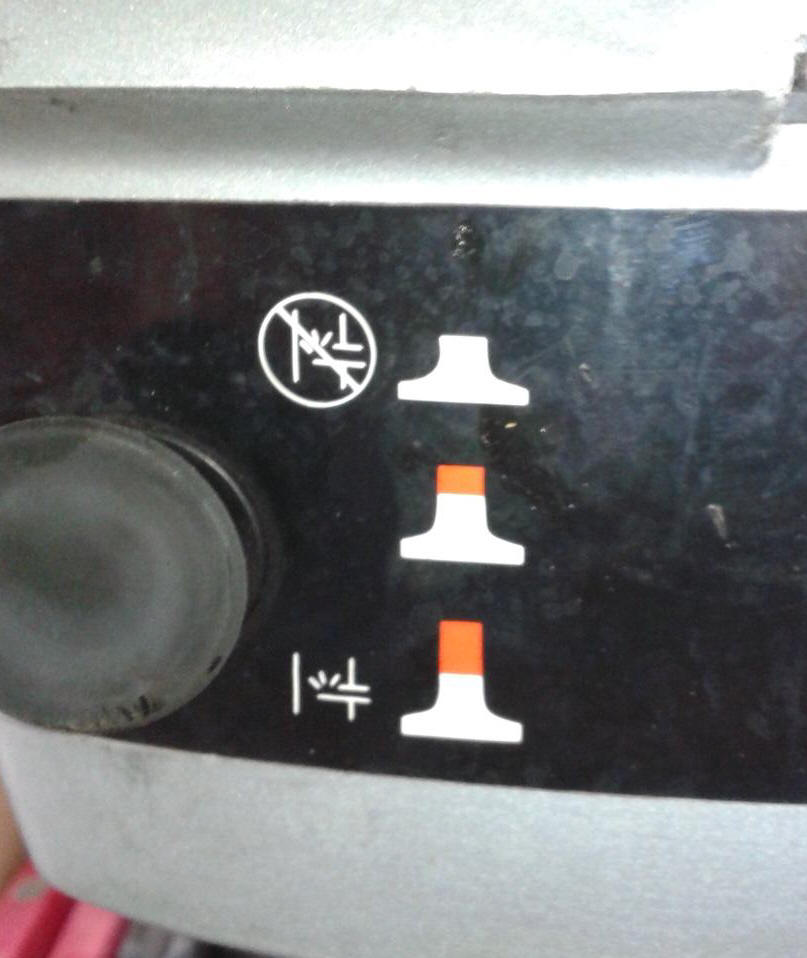
This primer system
used a knob similar to and in the same location as the butterfly choke knob
but in use, this choke knob is actually a
dual function choke and primer system. As you pull the knob all the
way out it is injecting fuel into the intake (it's like a syringe
and you can feel the tension as it's squirting the fuel into the carburetor)
this is the primer function. When you release the knob it should
go back a little over 1/2 of the way in by it's self with the red ring at the base of the
shaft still being visible, this is the choke position. After the motor
has warmed up a bit, you have to push the knob in all the way
(it
snaps in),
which is the running position.
| Fuel Primer unit exploded view diagram | Fuel Primer symbol decal on front of cowling |
|
|
 |
If your motor has this fuel primer system and you
are having problems where it seems that your motor is starving for fuel,
or runs better with the breather off, and you are beating your head
against the wall trying to figure out what is wrong, look at this type a
primer unit. There is a distinct possibility that if the internal
O-Rings are worn AND/OR the plunger is not fully retracted, you may be
getting a air leak into the fuel system.
Or it may not be seating when pushed back in,
thereby could be allowing extra fuel into the carburetor, flooding it
out.
Recommended
Fuel / Oil Mix :
The formula shown below will be on all modern 2 cycle oil sold
in the last 30 years or so. On most all of the pints and quart plastic
bottles of
TWC-3 oils there will be a narrow clear vertical
window on the edge of the bottles. On the sides of this window will have
numbers representing Ounces and Milliliters for other parts of the world.
Or you can purchase special measuring containers showing different ratios and
the amount of ounces needed.
If your motor is to where you have to mix the oil,
you need to know how much gasoline you will be needing, add the oil before you
fill the fuel tank so that the oil mixes better that just dumping it in after
you fuel up. However if that is not possible, guess, then add a majority of
what you think it will take, fuel up and then add the rest matching the amount of
gasoline you took on. If you are using portable fuel thanks, before hand,
when you fill it, add 1 gallon at a time, use a clean 3/8" or 1/2" dowel, mark
the dowel at each gallon and use it as a measuring stick. This way you can
refill a partly full tank with the known amount of oil.
A quart has 32 ounces of oil in it. So for a portable 3 gallon tank normally used on these smaller motors, to fill it using the 50:1 ratio would take 8 ounces, (1/2 pint) or 1/4 of the quart.
|
FUEL MIXING TABLE |
||||||
| Gallons of Gasoline |
Gasoline to Oil Ratio |
|||||
|
Ounces of Oil to be Added |
||||||
| 16:1 | 24:1 | 32:1 | 50:1 | 75-1 | 100:1 | |
| 1 | 8 | 5 | 4 | 3 | 2.5 | 2 |
| 2 | 16 | 11 | 8 | 5 | 4 | 3 |
| 3 | 24 | 16 | 12 | 8 | 6 | 4 |
| 4 | 32 | 21 | 16 | 11 | 8.5 | 6 |
| 5 | 40 | 27 | 20 | 13 | 10 | 7 |
| 6 | 48 | 32 | 24 | 16 | 12 | 8 |
The official OMC
fuel/oil mix for most outboard motors in this year ranges has for years been 50:1.
This means 50 parts of regular gasoline to 1 part of outboard motor oil.
Remember that this was before unleaded gasoline or even possibly an octane rating
that was listed at the pumps.
Now the recommended fuel is 87 octane
gasoline. Or before the outboard industry came up with any TWC
oil, much less the latest which is TWC-3 outboard motor oil. You probably will not see much of the older TWC-2
oil out there anymore. You can spend your money and purchase OMC
oil for about $7.50 a quart, or buy a name brand quart for $3.79. Sure the manufacturers want you to buy their
oil, and for a new motor under warranty, it may be advisable to do so. But the consensus from many experienced boaters is to use any good brand of oil, as long as it has the TWC-3 rating, it meets or exceeds the manufacturers
specifications. The TWC-3 represents,
Two cycle,
Water
Cooled, type
3
formula. The formula 3 has
decarbonizing additives
designed to be more compatible with the newer non-leaded fuel.
So from the above information, you can see that fuel and oils have changed dramatically since these motors were first brought out in 1974. In this instance, times have changed for the good, as we now have a better gasoline and way better outboard oils.
Fuel/oil standard mix on all the OMC motors that have needle roller bearings is 50-1 of TCW-3 standard outboard oil. However I
have found that since I troll much of the time, other than getting there
and back, I like to use a mix of 75-1, (and have even tried 100-1
with no side effects) but of a SYNTHETIC blend oil instead
of the standard oil. This gives me at least the same or better motor lubrication, plus
it gives me less smoke at a troll and the spark plugs last longer before
fouling.
Recoil Starter :
The
recoil starter uses a rope type spool system that works very much like
an automotive Bendix type starter
unit, only manually operated.
| Port side view of the spool type starter on a 1984 |
|
|
To
replace
the rope, you should first remove the spark plug wires for safety.
The following was taken from a 1981 service
manual but this later motor appears to use the same starter unit.
(1) Pull the rope out as far as you can, then allow it to retract less
than one revolution until the rope end of the spool faces the port
side of the motor. Lock the starter in this position by lifting
the starter pinion gear upward to engage the flywheel ring gear, do
this by slideing the slightly spread handles of a
pair of pliers under the gear, holding the gear upwards and into the
flywheel gears. (2) Remove the starter rope handle.
(3) Remove the rope from the spool. (4) Replace with
a new rope, which needs to be 1/8" dia., 59 1/2"
long, and burn the ends with match for about 1/2" to keep them from
unraveling and to be stiff so they will hold in the spool or anchor.
Thread the rope between the guide rod and spool, behind the spool and thru the slot in the spool as it came out of.
(5) Thread the rope thru the motor cover then install the handle.
(6) Hold the starter rope handle to keep it from rewinding too
rapidly, remove the pliers then allow the rope to rewind normally.
To remove the
starter unit from the power head, (1) pull the starter handle and form a
knot in the rope to prevent the rope to recoil while removing the
handle. Remove the handle. (2) remove the rope.
Hold the starter spool and slowly allow the starter main spring to
unwind completely. Remove both the bearing head screws along
with the front
spring retainer plate screw, allowing the plate to drop enough to
release the starter spring. Lift the starter unit up and away from
the powerhead. (3) remove everything, clean and inspect for wear.
To reassemble the cleaned starter unit, (1) place the upper bushing and starter head with the pinion gear spring onto the spool. (2) Insert the spring retainer (center shaft) in the spool. Align the slot in the gear with holes in the spool and spring retainer. Insert the roll pin with its split seam in a horizontal position to avoid dragging against the slot in the pinion gear. (3) DO NOT oil the gear or spool, this will attract dirt, causing pinion to bind on spool. (4) Insert the spring into the bottom of the spool, turn to engage with the slot of the spring retainer.
To replace the starter unit to the powerhead,
(1) Place the lower bushing in the spring retainer plate.
(2) Only attach the bottom retainer plate by the rear bolt that has just a few threads started so the plate is LOOSE, tip this plate so the front is open. Insert the spring down with the outer tail now between the bracket and the lowered plate.
(3) Place the spring down into the open area end of the outer spring out of the spool and hook it counterclockwise, onto the bottom retainer plate. Pull the bottom retainer plate up, locking the outer spring's tail and install the front retainer plate bolt and tighten the rear bolt.
(4) Insert the spring hook into the retainer plate slot by twisting it enough for the inner spring tail to slide into the spring carrier's bottom notch, locking it in place. (NOTE if the spring hook has broken off, you may be able to re-bend the end).
(5) Place the guide rod in the starter plate.
(6) Feed the rope in behind the rope guide and the spool's top from the inside and leave it lay out of the way until later.
(7) Install the starter assembly to the intake manifold bracket.
(8) When doing the final bolt down onto the top bearing plate #12 be sure that the gear clip's #7 tail straddles the upward protruding stud on the plate.
(9) Place a heavy duty screwdriver or a brace with a screwdriver bit in the slot in the top of the starter spool shaft. Wind the main spring about14 turns counterclockwise. The rope anchor hole in the spool should face to the port side of the powerhead.
(10) Now with the rope behind the spool and near the top, run the end through the spool anchor hole, tie a knot and pull it tight with as little as possible rope end protruding. Place it in the uppermost spool groove. Run the other end of the rope through the hole in the front cowling and attach the rope's handle, being sure it is to the LH side of the guide rod #14.
(10A) The above quote of the first sentence is a lot easier to type on paper than actually accomplished. This is because of the close tolerances behind the spool (to keep the cord from jumping out of the spool grooves). I have found that (not easy BUT it works), is to keep the cord out until you get the spool wound. And, yes, at the end of #9, poke one end through the spool anchor and tie a knot in the end. The other (loose end) poke it in from the rear on the top groove of the spool, push it in far enough that you can retrieve it from the front, (wire hook or needle nose pliers)/ Pull it all the way through). Now comes the fun part. Grind a small mild steel gas welding rod to a spire point. Poke it into the the end about 1/2" back, then reach up in the front LH side of the spool (looking rearward). Feed it behind the vertical guide rod (it is best to try for the second groove down). Get it started enough that you can now again using the sharpened welding rod, and penetrate the cord enough to pull it forward enough to by using needle nose pliers get ahold and pull it about 1/2 the way. This is because IF you had to use the second groove, you need to hold onto the rear section and PULLING UPWARD HARD, you can force the cord from the second grove into the top groove.
Now,
finish the installation by poking the cord through the hole in the
front cowling and tying it off in the pull handle.
| Exploded view of the 6 / 8 hp starter unit. |
 |
Upon re-assembly where you bolt down
the upper housing plate #12, the rope guide #14 rests in a shallow hole in this
upper plate. It has to go into the hole as you tighten the 2 attachment
bolts, otherwise you may break this plastic plate. At the same time the
plate has to go under the flywheel with minimal clearance. You can not
really see the hole, so this may take a bit of trial and error.
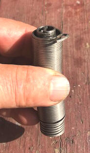
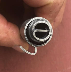
In the photos below, you can see the starter rewind spring (#3 in the illustrated view above). This is ONE spring wound with a inner coil AND a outer coil. The inner tail is pointing IN, while the tail on the outer section is formed as a hook. When installed, this end is DOWN. Do not wind it clockwise, or you will ruin it, and they (the spring alone) must be getting near being obsolete, because in 2022 they sell for near $124.99.
OH YES, one other thing the manuals don't tell you is that the retainer clip #7
above needs to ride in the grove at the very bottom of the drive gear. If
it is placed too low, (under the gear) the gear will drag on the flywheel gear
teeth. The large part just snaps over the gear, with the tail riding over
a upward protruding stud, which keeps this clip from rotating.
The only
grease/oil recommended is a minimal amount on the #2 lower Nylon bushing, with
most of the rest being Nylon and self-lubricating.
| Here the starter spring showing the inner & outer tails | Here a closer look at the bottom end |
 |
 |
High
Speed Safety
Switch :
These motors
utilized a system built into the starter using a cam on/near the throttle timing
plate cam to activate the lockout dog. In the illustration above the top
#10 dog rides on the aforementioned cam and allows the lower #10 dog to engage
notches in the starter hub directly under the top plate.
This locks the
starter spool from being pulled when the throttle grip is set any speed above
START. It will still start in gear below that. However some fishermen prefer not to have this feature on small trolling motors, so they
remove it. For doing it on this model, remove both #10 dogs along with the spring #9,
washer #8 and the retainer clip #11.
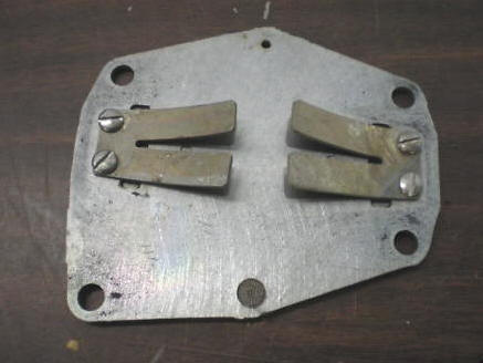
Reed Valves : These are a pretty simple and proven design. This plate mounts between the intake manifold and the block. In the photo below, the brass Vees are not the reeds themselves, but stoppers so the reeds do not get over bent and then break off. Also in the photo below you see 2 reeds per side for the 6hp and the early 8hp models. The later 8hp used basically the same but it has 3 reeds per side from 1988 on until the end of this series in 1991.
| Reed valve plate for a 6hp & 8hp from 1984 to 1987 |
 |
Cable
Type Throttle Linkage :
These 6 and 8 hp motors 1984 and later, used a push/pull cable throttle linkage system. The motor side of this throttle cable goes from the mounting
bracket on the port side (LH facing forward) into the lower pan and up under the carburetor,
around the opposite side
and up to the rear top of the block and thermostat housing. At the
thermostat housing, the end of the outer cable has a threaded end into an female
threaded plastic body that is attached to the thermostat housing by a bolt.
Adjustment in the throttle positioning is accomplished by unbolting and screwing
the outer plastic either in or out if you want to readjust the indicator pointer
to the speed letters.
If this
twist handle seems hard to twist or to not want to move, the cable may be dry and binding inside,
or the timing plate may also be dry and dragging. To test this, removing
the end of the cable at the timing plate, now see if the handle will now
twist. If not, then the problem is in the cable. You may be able to
remove the cable, then get some penetrating oil in to lubricate it.
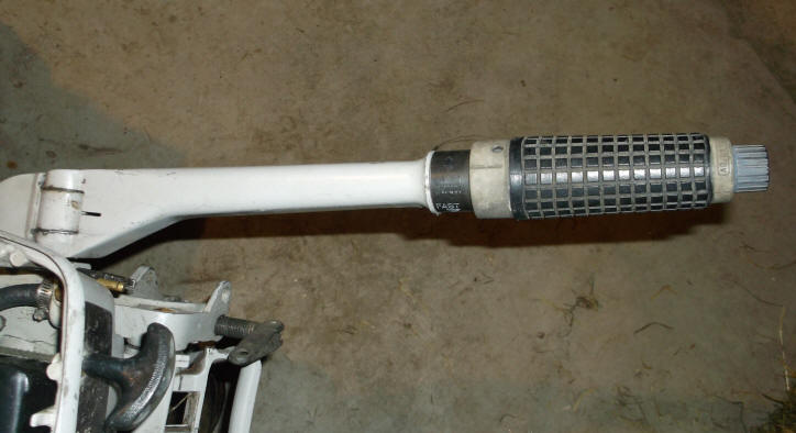
To disassemble this handle unit, you will notice two small 3/16" round holes near the rear of the twist unit at 180 degrees from each other, top and on the bottom. You need to use a couple of punches, depress both of these at the same time, while pulling the handle off front-wise. A helper can be useful in this instance. The twist grip slides off the end, but will not, UNLESS you screw in the slow speed ring all the way until it disengages allowing the kill switch to become unattached from the handle system (remember there are two wires to this kill switch). You can pull it forward just enough slack to remove the twist grip handle without cutting the kill switch wires. Inside this plastic handle is a dual rotating cam slot which a cross-pin enters into spacers and rollers which is in turn attached into the cable end. When disassembling these be careful to not loose this pin, as it may drop out unknowingly. These spacers and rollers are just slid onto a center pin and can/will fall off when removed. Locate and remove them, for safe keeping.
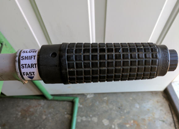
After much usage the embossed Slow-Start-Fast speed indicators on the handle may get worn, however usually the start position is on top. The start raised rib on the twist handle is usually aligned with what may have been the START position on the handle. Or, replacements are still available (slightly different symbol design however) #0327944 Throttle Control plate and sells for $20.99. OR do the Red-Neck computer generated/printed with clear shipping tape covered version as seen below. Here, the trick is to cut the tape slightly oversize for the printed paper so that you have about 1/8" to hold it in place. If it fails down the road, just make another one. This method could be used for many other motors other than just this one.
| Here a new label was computer generated, printed & then covered with clear shipping tape to attach it to the original obliterated speed indicators |
 |
When twisting the handle, the cable moves in or out, controlling the timing plate and carburetor cam.
The photo below shows a 1984 with a multi -function idle/kill button on the end of the twist knob. This style handle is activated by a internal cable from the handle to the carburetor. Inside the outer rotating knob, which is a low speed adjustment, is also a push button kill button. This rotating button/end knob when used for an low speed adjustment does not have any carburetor adjustment, but is used mostly by trolling fishermen who want a preset low speed other than having to each time they twist the handle to any other position, and want to go back to their preset slow position.
In essence this is just a fine tuned low speed setting. The outer knob can be turned in or out. Out will usually come to a stop after a few turns, where in, once it has passed the few threads on the large inner section of this knob, will just keep rotating, but will do nothing because it has simply ran out of threads. If you can not get it to adjust, the cable to the linkage to the timing plate by unbolting it there and screwing the outer plastic either in or out if you want to readjust the indicator pointer to the speed letters. This can become frustrating.
Over the years the rubber kill button on the end will become hardened and may not function as designed. And if the slow speed ring is turned all the was in, it may even hold the kill button in, shorting out the ignition, not allowing the motor to start. Or it can have salt corrosion on the inside contact points, preventing it from shorting out and killing the motor.
You can try to rejuvenate this rubber knob if it is still intact. DO NOT try to remove the metal inner stop contact. One method to rejuvenate the hard rubber is to soak it in Silicone for a few days. My method was to use some silicone waterproofing spray (that I could never get to perform right anyway), use a quart Zip-lock baggie and spray enough of this in to allow it to soak (both in and out) for a few days. Leave it in until it becomes pliable again so the inner metal contact of the button will be pushed forward and away from the contacts.
To get this button off, once you get this rubber speed twist grip off, the kill button is buried inside the plastic slow speed knob, with just the outer end of the kill button sticking out. Once you have the twist grip pulled off the front of the tiller handle, the kill button will be attached to the switch behind it with the 2 black wires leading back into the tiller handle and back under the powerhead. Look closely and rearward from the front of the kill button there will be a joint between the button and the switch body about 1 1/16" back. The button is slid over a slight ridge and retained on this ridge by snapping over it, the button is glued at this joint to waterproof it. With a strong knife, cut down into this glue until a you hit the plastic body. Cut all the way around. Then pry the button forward off the switch with a small screwdriver.
This kill switch has been discontinued, but a conversion kit is available "0392968 — STOP SWITCH ASSY. Unavailable, replaced by 0398744 but also Discontinued. Replaced by 0583975 - Idle Stop Switch Kit $143.99, discounted price from some dealers $90.70. This kit must be from some other model that seems to fit.
| To disassemble, push in on the 2 plungers simultaneously (top & bottom) & pull the twist handle forward. This reveals the slider cams which engage a cross-pin which activates the in/out cable movement. |
 |
In the photo below you will see the black plastic threaded outer cable attachment bolt on the thermostat housing and the pivot bolt at the end of the inner cable/ timing plate arm.
You will also see a spare prop shear pin that I have electrical taped to the plastic outer cable end.
Here you can
adjust the throttle linkage and throttle twist grip timing. It is possible to try to adjust
the twist grip knob indicator to synchronize with a SLOW setting, but to get it so out of time that
you can not achieve a higher RPM, WITH THE COWLING ON. This is because
this arm can be hitting the inside of the cowling, stopping high speed running.
Therefore you may have to compromise for a SLOW/ idle setting on the twist grip
indicator.
| Here the rear end of the throttle cable is secured on top of the thermostat housing with the outer end secured at the pivot bolt, which is the adjustment. |
 |
Midsection & Trim / Tilt
:
There is a black
flat knob (shown in the photo below), located
close to the transom clamps of engine. When put in one position, it locks
the motor to the cross shaft, effectively locking it in that position, when the
knob is turned to the opposite position, it allows the motor to freely tilt up
or down. It has a sketch of a boat with the
motor raised on one side of this flat knob indicating it can be raised.
This lock needs to be in the lock position if you use the reverse gear on the
motor so it won't kick up. However, if you plan on using the motor for
trolling in the shallows where you could drag the skeg, leave it unlocked.
Or use the shallow water drive latch located on the starboard side of the lower
transom bracket. This knob is made of black plastic and it it gets gunked
up, or sticky AND the operator is not sure which way it needs to be moved, the
thin outer wings of this knob can become broken off. At this stage of the
game, TS, no factory replacement is available. And the owner now does not
know which way to move it, (which is usually locked into the NON-TILT POSITION).
The only way to get the housing now tilted or to access the inner part of this
knob shaft is to pull the transom clamp adjustment pin (#23) in the illustration
below. This is the part that the lock fastens onto, so by pulling this pin out, you can now
raise the motor, inspect, lubricate things, maybe even remove the knob
shaft for repair.
| Here the tilt lock knob and the pivoting carry handle |
 |
There is a fold out carrying handle tucked into the front of the clamping bracket. The clamp screws are 5/8" diameter.
Shallow Water Drive
:
There
is a shallow water drive provision on the RH side of the pivot/mounting unit #65
in the parts illustration below. With the tilt knob activated
so that the motor can be tilted up, lift the motor up slightly, move this #65
lever so it goes over center and you now have the lower unit held in a position
about even with the bottom of the boat.
The twist grip throttle is activated by
by a cable system that has a slow speed adjustment knob and a kill button on the outer end.
The upper and lower motor mounts are made
of rubber and are the same part. They appear to be very durable, plus easy to get to.
|
Midsection exploded view |
|
|
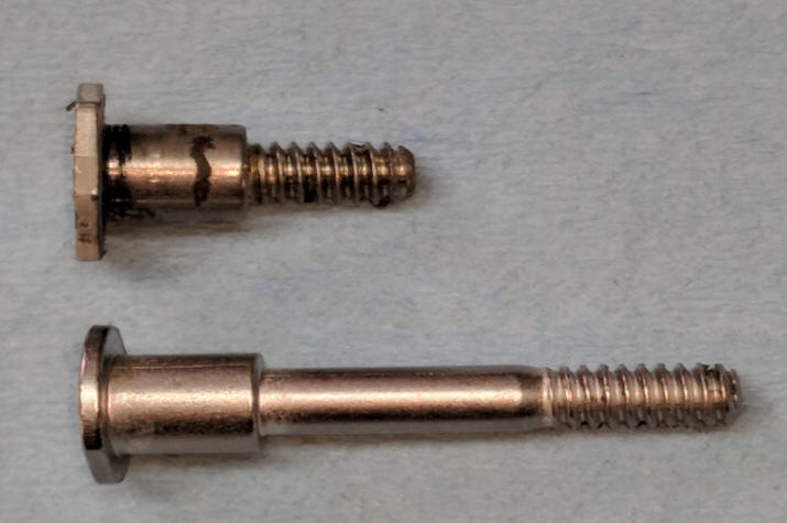
Tilt Lock Bolt : The pivot bolt (#97 in the illustration above) for the tilt lock initially was threaded into the RH motor clamp bracket. However IF the motor was left in this locked up position when traveling over rough roads, the threaded stud end could break off inside the bracket. The factory either before the end of this series, made a change in this bolt, or made a new improved bolt as a replacement.
In the photo below you see the older original short bolt (top of the photo) that is threaded into the clamp bracket. This is prone to breaking the head off at the juncture of the shoulder and the threads. The new bolt is designed to replace the old bolt, by drilling out the boss it is threaded into, and installing a nut on the outside. In drilling out this, you will need to make an accurate mark AND center punch the bracket from the outside, as it will be impossible to drill it out from the inside unless you do a lot of removing of the clamp bracket parts.
The one I did, the inner hole was very close to being centered with the outer round boss. The threads are 1/4" X 20 NC, so initially drill with a 3/16" size drill, be sure you are drilling as square with the bracket as possible. The inner threaded hole is longer than the broken off threaded bolt. Your drill will go through the aluminum bracket and then a short distance until it starts drilling into the broken threads. Hopefully you will be close, but if not, angle the drill, trying to remove what is left. Then move on to a 1/4" drill and open up that hole to accept the new bolt. On the one I repaired, the threads on the new bolt were not long enough, so I put it in my metal lathe and moved the shoulder back 1/16".
| Replacement tilt lock bolt on the bottom |
 i i |
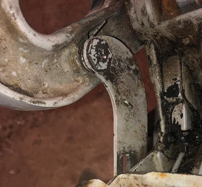
Now after you get the bolt replaced do you know how where the spring #95 goes? The pivot bolt has a shoulder about twice as wide as the lock lever, which space is for the spring. You will notice a small hole in the lever about an inch away from it's pivot hole. This is for the longer hooked tail of the spring to go into. The spring then goes over the bolt and when assembled between the inside of the transom clamp sideplate, with the shorter tail going up and tucked inside the lip of the sideplate as seen in the photo below.
| Location of the tilt lock spring |
 |
Muffler
:
These motors have a small plastic cover that covers the upper exhaust vent on
the rear of the midsection (#80 in the above illustration). This does muffle
the motor some, but in reality it
was called a "water outlet" on the earlier models. This muffler/outlet
allows for some outlet water to mix with the exhaust gasses to cool the housing
and at the same time allows only a small amount of exhaust with some spitting
water, as an indicator of sorts, some may call it second exhaust port, however
in actuality, in these smaller engines you could say it is an idle bypass,
because at idle speeds there is not enough exhaust pressure to overcome the
under-water pressure out the larger hole near the prop.
So if you see a slight amount of blackish oil coming out of the bottom of this, it is normal.
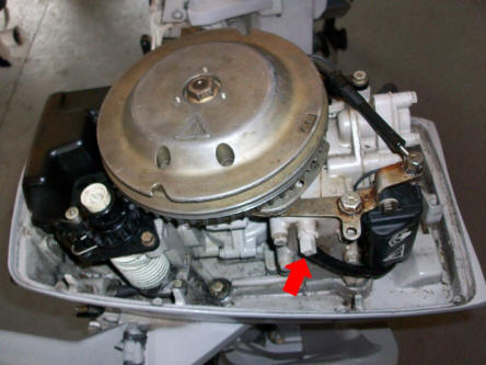
Water Indicator : These motors have the tell tale water indicator system common with most of the later motors. Here in the photo below you see an Ell coming off the water jacket and a hose to under the head to a hole out the RH side of the lower cowling. These seem to be a bit more trouble free as related to plugging up as the outlet hose to the overboard tell tale takes off the side-plate cover near the top instead of the bottom. This appears to help a bit in that it is less susceptible there to less debris plugging this tube.
| Tell-tale water indicator outlet off the motor |
 |
Water Intake :
These motors main
water supply to the water pump comes from a screened tube right behind
the prop in the exhaust outlet which was carried over from earlier
motors. Water is forced into the
screened intake to the water pump by the prop thrust. Some users
report that when running these motors in a barrel, (usually a small
one) that the prop has to be installed and usually in gear as apparently
they need to get more water pushed to the water pump by the prop to
get enough to cool when running at over an idle.
There is no stainless steel intake plate on the left side above the cavitation plate like the previous versions. Aftermarket flush kits for this motor are obsolete and rather scarce. There is really no provision currently available for a easy muff system to run this motor out of a tank. But there is hope. I think that I may be able, (by tearing mine down) to figure out a way to drill/tap/modify the lower unit near the water pump to where I may be able to utilize the later screw in flush adapters on this motor. But that is a project in itself.
Flushing This Motor : These motor's main water supply to the water pump comes from a screened tube right behind the prop in the exhaust outlet which utilizes the thrust from the prop to initially push water up to the water pump. This method of water intake does not allow the newer type of flushing muffs to be used. At Soon after these motors came out with this type a water intake system, Tempo made Flush Kits #918FAA, MPW LONG OBSOLETE. But there is a method that i devised that allows the use of a flush Adapter to a garden hose, For a link to that article CLICK HERE.
Overheat Problems
at Troll or in Tank
:
If you happen to have
the motor overheating at slow speeds, you might consider looking at the
water intake screen tube which is situated in the lower unit directly
behind the prop. This is placed here so that the prop thrust
pushes fresh water into this slotted screen tube. This
slotted screen could be inadvertently blocked enough that these holes
could partially block water intake at
a slow speed.
This slotted screen is made
of plastic which would be
hard to remove and save after many years, plus it is expensive to replace.
So using
a small nail or similar tool, you should be able to carefully clean any
debris from the holes clear enough to make a difference
When using this motor in a tank, always run it in
forward gear as the water pickup tube is directly behind the prop, with the idea
the prop will help push water into the pickup tube. If the tube is partly
plugged and the motor is ran mostly in neutral, the motor may not be getting
enough cooling water and overheat.
Water Pump/Impeller : To get to the water pump, you need to drop the lower unit (gearbox), First you need to remove #5 and #56 bolts as shown in the illustrated parts photo below. This should allow the lower unit, (water pump assembly to drop down and be able to be removed from the exhaust housing. These motors utilize a different shifting system than the previous motors. It rotates instead of moving vertically as seen by the #10 & #78 bevel gears (located under the carburetor) shown in the midsection exploded views below . The upper end of the lower unit shifting rod is machined to match the #78 bevel gear coupler, which should just slide out and down when you drop the lower unit. The whole shifting rod then drops down and then out the bottom with the lower unit. This is a lot simpler to disassemble than the previous years models.
Now what if it does not come off, by dropping down and away from the exhaust housing? In all probability, some previous repairman may not have greased the upper driveshaft spline an it is stuck in the lower crankshaft, OR the shifting rod coupler under the motor has been burred. This can be a problem, but most of us have relied on wedging it off, possibly by using a couple of large screwdrivers, but the plastic timber fallers wedges are ideal in that they won't mar the housings. As said above, the shifting rod just slides into a rotating mating couple up under the carburetor. If it is really seized, and you have to wedge it for a distance, The driveshaft is not really anchored in the gearbox, but again on a spline. The driveshaft is secured in the water pump only by the impeller key in a slot in the driveshaft and being inside the water pump housing. So if all else fails, and you have to force the lower unit down far enough the impeller key will be forced up through the top of the water pump housing, (in all likelihood, ruining it), but at least you can get to things now as the driveshaft will still be seized in the powerhead, but at least the lower unit is off. You might luck out on the damage to the water pump housing and only the top seal (#55) was damaged.
Now you can rap on the
lower end of the driveshaft, trying to jar it loose, and then in a location of
it that is protruding, use a Vise Grip pliers on this shaft and beat the
pliers down with a large hammer. If the shaft is marred because of the
pliers and you chose a location that was not critical, the marring is
inconsequential and can be filed off.
Replacing it back into the midsection housing and re-aligning it after replacing the
impeller may prove interesting. This CAN all happen without having to
remove the powerhead, however it may take a bit of jiggling to get things to
slide back together. The first part to align is the water tube, which
slides into the long upper snout of the housing. This snout is
considerably longer than most, so it helps get the tube started while you can
still see inside the midsection from below using a flashlight. The
tube's lower end is cut on a angle to help facilitate easy entry into the
grommet in the upper end of the snout, but you may want to grease the end of the
tube.
Second the driveshaft and finally
the shifting rod. Initially I was worried about the shifting rod's
re-alignment, but that was easy. The hard part was to align the
driveshaft. It took a lot of eyeballing for the lower unit's upper mating
surface to be even with the midsection's lower mating surface. After the
driveshaft slid into the splines by slightly rotating the flywheel as you push
up, the lower unit slid up to within about 3/8" then it went into the shifting
rod gear easily. You can not see the shifting rod as it goes up inside
it's own pocket, but it must have a internal tapered area at the top because
things just slide in fine. I like to put the motor in neutral before I
pull the lower unit, and then if something gets moved, it is easier to remember
to find neutral than which gear it was in when you pulled it apart. But
here to engage the driveshaft spines with the crankshaft, you may then have to
play shifting it in a gear and rotate the flywheel a bit instead of the prop, or
both.
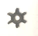
OMC / Bombardier #0389576 water pump
impeller $18.00 This impeller fits Evinrude and Johnson 4hp,
1980-1992; 4.5hp & 7.5hp, 1980-1983; 5hp, 1996-2005; 6hp, and 8hp from 1984 to
2005 2 stroke engines.
| New Water pump impeller #0389576 | Water pump assembly |
 |
|
| Used water pump impeller #0389576 |
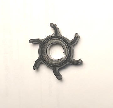 |
Now for a confusing part. Since we are dealing with a used motor
with no known repair history, we are not sure what had been previously done.
I purchased the proper identified (I thought) impeller from the parts manual
#0389576. Upon
removal of the water pump, I found the new impeller was the right diameter but thinner in
vertical dimensions. The new replacement was .845" thick while the
existing one in this motor was .700" thick, but mine was the first year of
production for this series of motors. However my water pump housing was #0389577
which matched the #0389576 impeller. As luck would have it the
existing one appears to have recently been replaced, so I just reinstalled it.
I was not clear if mine had a replacement water pump OR
if I got the wrong impeller.
OK, a few years later the
existing impeller got so
stiff that it took a set and refused to pump adequate water, so I bought another
impeller, same part number and the correct one this time. I now suspect
the other earlier impeller was packaged wrong, or was a return that had somehow gotten swapped.
The experts
say to not reuse a lower water pump plate if it is scored. But they are
now obsolete. Well this one
had a couple of deep circular partial grooves in it. I disregarded the
smaller diameter one near where the seal ridge of the impeller rubbed. But
there was one larger wear groove out farther and near the outer edge. I took it to my
2" band-sander and using a worn
240 grit belt, sanded this stainless steel plate from all directions to
removed minute metal as evenly as possible. OH yes, you will need to dip
into water after each sanding, as it gets HOT.
Thinning this plate should not have any effect on reliability as long as it was
smooth, and this plate uses a
gasket both on top and bottom, and the pump housing bolts on top. Maybe
not recommended, but it worked.
The
stainless steel cup
looked in better condition so nothing was needed on it.
Just in case that
you lost the impeller key (drive pin) #0300611, it is .125" dia. x .390"
OAL.
Water Pump Not Pumping Water Into Engine : After you rebuilt the water pump, and it does not pump right or very little, what is wrong? Before going too far, is the pee hole free and clear. To check this on this motor (when running), simply pull the rubber water tube off the Ell connection on the Port Side on the upper water jacket, this will tell you if there is water in the engine.
Other than that, the most likely thing to look for is the water tube did not slide into the pump tube grommet as you slid the lower unit up as you also aligned the driveshaft splines and the shifting shaft. This water tube has to go in first, and there is very little room to see when holding a flashlight.
Or the
impeller was installed wrong, either the vanes
are rotating backwards or a couple may be that way. In installing a new
impeller, you will be inserting it from the bottom, so you should install it
"backwards" or counterclockwise. This then relates to clockwise when
it is flipped over and the pump body is bolted to the lower unit.
One thing I have found is that the smaller the diameter of the impeller, (as is
the case here) the harder it is to get those vanes to mind you when trying to
get them inside the pump cup.
Or the drive key could have fallen out upon the semi-final slide down assembly of the
pump to the unit.
And do not forget to check for any debris in the intake or
pickup tube behind the prop that might be blocking water passage up into the
water pump.
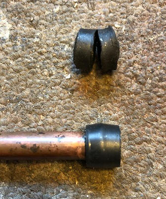
Finally the upper water tube grommet may be
deteriorated and leaking water before it gets into the block. This is the
last thing to look at because it involves removing the powerhead, as this tube
grommet sets right under the block. The photo below shows a
deteriorated grommet, that was still functioning however.
The top of the
copper water tube has a slight flare. The rubber grommet is built to be slid onto
and OVER the flare, allowing the flare to be retained in the center of the
grommet that is made to accept the flare. In the photo below, you can see
the old damaged grommet on top, being partly broken at the flare point when
assembled.
| Deteriorated upper grommet #324045, with a new one installed below |
 |
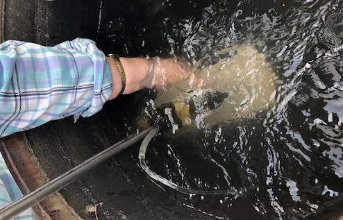
OK, so you have pulled the lower unit off 3
times, as it still was not pumping water right. Your thoughts are, just
what did I do wrong, OR is there something that I missed? It is about time
to get serious. With the water pump installed on the lower unit, and the
shifting rod rotated so that it is in forward gear, (needed to push prop water
into the pickup tube) you might consider then to attach a drill motor to the
driveshaft, set it (the drill) to forward rotation, then to submerge the lower
unit into a water barrel deep enough to cover the pump, and see if the darned
thing pumps water. It really did not need to been in gear, but on this
model the water intake is behind the prop (forcing water in) and I wanted to be
sure that I was simulating true operation of this unit. This will soon tell you instead of finding out after it
is installed, and is still wrong, as water should come flowing up out the water
tube outlet.
In the photo below, a 8" piece of clear Vinyl tubing was pushed into the pump outlet grommet (where the copper tube to the powerhead would be inserted) to ensure that we could get the pump body submerged, and yet be able to see the flow from the pump, as can be seen of the output water arcing up and down. FYI, the drill was NOT ran at a high speed in this photo, but enough to get an indication of flow. It was ran faster earlier with considerable flow, but was harder to hold with the full prop force and it rotating close to the fingers, which full force was not needed for this photo. And you can see flow coming out of the Vinyl tube that is attached to the output of the pump.
| Here the lower unit is submerged in a water test tank & driven by a drill motor onto the driveshaft as a function test |
 |
Lower Unit
:
They have a
unitized gearcase accessible from the rear instead of the previous gearcase that
split horizontally at the prop shaft line. The prop is driven on by a
stainless steel shear pin 3/16"dia. X 1 1/4" long. There is a
prop shaft nose cap on the rear that is
retained by a cotter pin.
The new rotating shifting shaft cam (with 3
indents for gear positions) in
the lower unit, pushes a internal spring loaded rod inside the prop shaft that is in contact with the
shifting clutch dog. This spring always has tension so the clutch dog is
always pushing the dog in the forward position, but easily shifted into neutral
and reverse, but uses the spring as an assist for engaging the forward gear.
The water intake is in the exhaust tube
right behind the prop as used in the older smaller OMC engines as seen by the
screen #24 hanging down in the exploded drawing below. And it offers
no real opportunity to attach a currently made flushing attachment. Treat
it with love and care as new replacement ones sell for $75.
One thing they made provisions for was a recessed location in the lower unit to install a zinc anode, #47 in the exploded views below.
One thing I may warn you is that when you try to reinstall the lower drain/fill plug, is that IF the plastic washer remains in the hole, you may very easily NOT be able to start the threads straight. And this threaded hole sets at a slight angle with the outer housing when it is tightened in tight. If it looks like it is going in crooked, stop before you ruin what threads are left. If the unit is full of oil, you may be able to lay it (the motor) down enough to be able to remove the plug without a lot of oil draining out. A 3/8" X 16 NC tap can be ran in VERY CAREFULLY to clean up the slightly cross-threaded threads. AGAIN, VERY CAREFULLY.
Remember that when you check/change
gear oil, it is recommended to replace the drain plug plastic washer (#0311598)
as they seem to be the most likely point of a leak. Now somewhere along
the line the factory made a change in these drain/fill plugs by eliminating the
washer and incorporating a Neoprene O-Ring as as seal. Maybe this came
about because of the paragraph above.
| Here the lower unit is in exploded view for a 1984, with the long & extra long shaft spacers are on the upper left |
 |
To remove the lower unit on these motors there is one bolt in front that is quite visible (#5 for a short or extra long shaft, or #58 for a long shaft in the illustration above). There are also two more bolts underneath, above the prop (#56). Removing all three of these should allow the lower unit to be withdrawn from the exhaust housing and down to where you can remove it to access the water pump housing (#34).
If this does not allow the lower
unit to drop down, possibly some previous mechanic did not grease the upper
driveshaft splines and it is stuck in the crankshaft.
If this is the case, wooden
wedges driven equally around the midsection/lower unit may be your alternative.
OR, as I have found on one motor, the shifting rod flat apparently got worn
enough that it raised a burr where it entered the female coupler right below the
powerhead, creating resistance. Here all you can do is wedge the two (gearcase
and exhaust housing) apart. The simple wedge found to accomplish this is
timber fallers plastic wedges.
Propeller
:
The
prop is a NON THRU THE HUB type.
This prop does have a shear pin and the plastic
bullet nose cap is just a retainer that is held in place by the cotter-pin.
There is no clutch or slip hub in this prop, but does have a rubber hub bonded to the prop along with to the bronze hub.
On my prop the rubber must have gotten some corrosion between the prop and the
inner hub, forcing the hub forward about 1/16". This made it very hard to
get the shear pin in place while still having the brass spacer #54 shown above.
I tried to press the hub rearward, but no avail as the rubber was still bonded
(or stuck), so I simply chucked the prop in
the lathe and removed that amount off the rear of the prop to allow the spacer
to be in place and to accept the cotter pin #53.
Propellers need to be free of dings or non symmetrical shapes to be balanced so the motor will run without a lot of excess vibration. Any time you see rock dings, clean them up with a file, and try to keep all the blades as equal as possible. Slight bends can be straightened up with a small hammer against a heavy steel plate.
The prop shaft is .531 or 17/32".
why this odd dia. ? Well my guess is that since most roller bearings and seals are actually made in
metric sizes, this .531 equals 13.5mm, so the seals would be more readily
available.
Prop specifications, all being 3 blade props. The
actual size and pitch may have changed over the period of production.
There were at least three different sizes, the OMC / Bombardier, 9 1/4 X 6
1/2" (0392183), 8 1/2" X 9" (#0390237)
and 8" X 7" (#0778796). All will fit and function, but usually
the lesser diameter and pitched props used on the 8 hp. While the larger less
pitched used on the Sailmaster requiring more thrust for a heavier boat. However after 40 years it is hard telling what actually was original to any
motor.
Or the aftermarket Michigan Wheel propeller, 1980 and newer Johnson 3 blade 8 1/2" X 9" 6 / 8hp #012032, at $81.99, seems to be a compromise of all the OMC props.
Shear Pin : The shear (drive) pin (#51 in the above illustration) on this model goes into the prop on the rear section and inside the plastic cap, (some older models go on the front). The size of this shear pin is 3/16" diameter X 1 1/4" long. One thing that may help in re-installing this pin or if you make your own, is to grind at least one of the ends at a slight taper.
Propeller
Nut :
There
is no
prop nut on this model, but a plastic nose cone (called a prop shaft cap,
#032694), is held in place by the cap's cotter pin.
Propeller Nut Cotter Pin : The stainless steel cotter pin holding the plastic cap on is 1/8" diameter X 1 5/8" overall length.
Thrust Washer : Between the prop and this cap is a brass thrust washer #0324689, (#54 in the above illustration). This thrust washer basically takes up any slack between the prop and the shear pin.
| Rear propeller shaft cap piece #0324694 | Thrust Washer #0324689 |
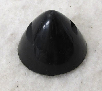 |
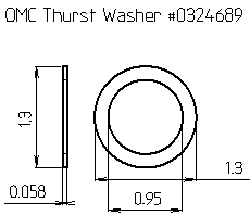 |
Paint
: OMC / Bombardier paint, spray can, Ivory #173744,
Johnson Platinum Gray #174069 but
superseded to
#771246, on the can it says for 1984
to 1987 motors.
Powerhead Removal : Here it is best to remove the lower unit first, as you will not be able to align the water tube into the pump outlet from the top. You do not need to remove the 4 (9/16" headed) bolts seen from above that hold the lower pan to the exhaust housing, but the 6 (3/8" headed) bolts from underneath.
Then
you will then need to remove the starter unit, carb, coils,
powerpack, flywheel and timing plate assembly sooner or later,
depending on your preferences, now or later, and whether you are
going to just replace the upper water tube grommet or do a complete
rebuild.
When all is
loose, you may have to pry the block off at the mating gasket as
they are often stuck to the gasket. It lifts straight up, along with
the exhaust tube and water tube from the water pump. It may
take a bit of jiggling as there are (2) 25 cent size rubber bushings
between the exhaust tube and the exhaust housing, which are
illustration #77 part #327030 — Silencing Pad. There are
locations for 4 of these rubber pads, but only the top ones on each
side are used on this motor.
| Here is the exhaust tube, showing the silencer pad |
 |
This will be something that you will probably not normally encounter, but as a side note, on this motor, when replacing a water pump impeller, the water tube from the pump to the powerhead was rather loose and it was not pumping water as much as it should. Not knowing how bad the upper tube grommet was, it was probably best to be sure before I burned up a motor. I found that the upper grommet was somewhat deteriorated, but probably salvageable, by wrapping a strand of rope graphite imbedded water pump packing around and below the grommet, tightening it into the exhaust tube's mating cavity gained me a few years of run time.
| Here, the powerhead & exhaust tube assembly is off the Midsection / lower cowling |
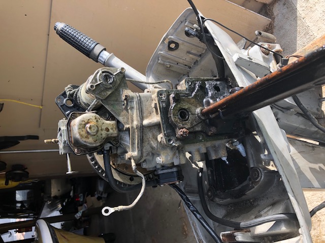 |
I also found a jagged 5/8" hole in Port side of the exhaust tube where it bolts to the block. This surely was not normal and it looked kind of like someone had tried to weld it up at one time. I have seen small holes (3/16") here on some larger motors as a pressure relief system when the motor is on the boat and in the water to facilitate easier starting, when cranking. But this exhaust tube is short enough that it does not connect to the lower unit, along with the tube itself is short enough (8") that it is probably 12" above the water level, again not creating a sealed area in the water pump cavity .
My decision was to make a .080" aluminum patch and screw it onto the then tapped threaded housing along with bedding it in JB Weld. In the photos below you can see the start of my endeavor. In the finished part, the hole on the inside was also filled with JB Weld and the screw ends ground down to match the inner surface. The screw size was #6-32.
| Here is my aluminum patch from the outside | Here you can see the patched hole from the inside before the JB Weld |
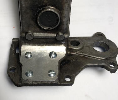 |
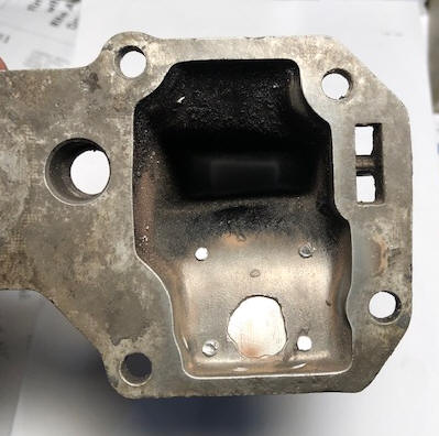 |
Rebuild/Re-Ring Powerhead : This motor was not pumping water consistently, enough to keep the motor from getting hot enough to stop running numerous times, so the thought was to do a complete rebuild concentrating initially on the water pump and anything related to the lower water system. A compression check was done and surprisingly it was 105/97. But I was pretty sure there had been damage done because of overheating.
Here, in order to tear the motor down enough to get inside, there are six 5/16" bolts holding the front part of the block to the rear part. Four of these are visible, the other two are buried under the intake manifold. These two require a thin wall 1/2" socket to remove them. I did not have suck an animal, so searching my miscellaneous box, I found a 13mm 1/4" drive cheap socket. By grinding down the outside enough to give clearance, I got these 2 bolts out.
And upon tear down I found the top ring on #1 was carboned up
at the ring ends, and both cylinders were scored lengthwise.
As on any motor rebuild, always mark the top of the piston with the number of the cylinder, l (like #1/#2 for Top/Bottom). And also remember which side of the piston was on the intake or exhaust side, as they will not function if not in correctly by the piston hitting the head. And mark the rod and rod caps, by filing (felt marking does not stay) one mark on both the rod and another on the cap for the top #1, and two marks on the bottom rod/cap so you have no problem reassembling them in the same position as they came off. I try to always do this on the intake (spark plug) side.
ONE thing on this motor to be aware of is that the rod and center main bearings are LOOSE needles, and when the caps come off, these needles may go everywhere, even down in side the block. I did find in the factory service manual, the number of needles (28) for the center main, but it does mention the number in the aftermarket service manuals, so maybe best to just count and keep them separate. My suggestion is to have a magnet close by that area when lifting the rod and main bearings off. And the main bearings are slightly larger than the rod needles
I verified both the numbers of main and rod bearing needles by doing a full sized CAD drawing for both. For the center main bearing needles, the number is 28. For the rods, my count was 30 needles. The factory service shop manual is rather unclear, but if you know the procedure, this info is there if you really look. And these bearings were only sold in sets with the liners (but not available in 2021), meaning you are SOL if the liners are damaged, unless you can find a used donor motor for parts.
Needle sizes for the center main ones are .0985" dia. X .609" long. For the rods, they are .0780" dia. X .612". A substitute for a few lost needles could be ordinary drill bits (cut to length). Here, for the center main, 2.5mm (.0984") would be ideal, or #40 drill equals .0980". And for the rods, 5/64" equals .0781" all which would probably work well, as you will not be replacing them all.
With everything torn clear down, both cylinders showed scoring lengthwise
as seen in the LH photo below. After much honing with a brake wheel cylinder hone,
the scores were removed. In doing this with a drill motor set on high
speed, and by squirting WD40 into the cylinder and onto the turning hone stones (to keep
them from becoming clogged), things went well.
| Here you can see the scored bores | Here you see the honing process |
|
|
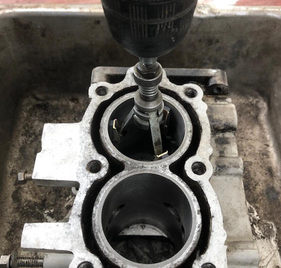 |
With all the parts now cleaned after the honing, as a
added security measure, I ran a corresponding thread tap into all the holes of
the head and block, (all of them).
At this time, the water jacket/passages
were cleaned of hardened deposits.
Then came checking the head and block
surfaces for warpage. Both needed attention. This process usually
involves using a piece of window glass and valve grinding compound, with much
elbow grease of moving the part on top and in various locations to ensure it
does not get all worn down in one location. This time, I tried something
different as the glass that I had, I did not want it defaced. So I tried
new 8 1/2" X 11" sheets of sandpaper on top of the flat glass instead. I settled on
#100 grit, as the #220 wore down too fast.
However using this method, not having 3 hands, I found that I had to hold the paper with one and push the part with the other, and reposition the paper (to get a equal good grit bite) after each push. This method came out well and did not require the messy clean up afterwards. This method was also used to clean up the side plate's inner surface.
| Here are both the head & block after being partly lapped, note the dark areas still at the cylinder joint | Here you can see the final lapping of the metal around the matings of the cylinders |
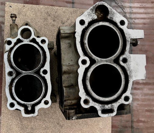 |
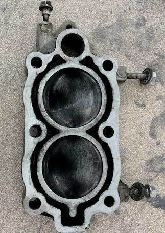 |
Reassemble :
The pistons needed to have the old rings removed and the ring glands
cleaned of any debris or carbon. In replacing the rings, this has
to be done by hand and CAREFULLY so that you do not break a new ring
(they are rather delicate compared to automobile rings). The pistons
have a small pin in the ring groove at 180 degrees of each other (and
short enough that the lips on the ring overlap it by 1/2).
At the ends of the rings are a shallow recess that matches the pin.
This is designed so that since this is a 2 cycle and uses ports in the
cylinder, to not have a ring end be positioned at one of these port
openings to help against it's possible breakage.
With the rings
loosely on the piston, and it slid into the
bore, slide the piston in until it is stopped by the now protruding ring, now very
carefully depress the ring on all sides at the same time, forcing it in
enough to now push the piston deep enough for the ring to now be slid inside
the bore. Repeat this for the other ring.
Here, the worst part of this rebuild was getting the loose needle bearings in place (and have them STAY THERE) without ruining the liners when you tighten the caps. This involves both the the rod bearings and the center main bearing, AND thin Stainless Steel bearing liners so the needles had something harder to run against as compared to the aluminum block, rods and caps.
These liners were made with each end like an shallow arrow, one end pointed, with the other Vee'd so that the needles did not have a straight edge, but the tapered of the arrow/Vee to catch on. So these liners also had to match (inner/outer--male/female) while being invisible at assembly time.
| Here are the connecting rod needles & liners as mentioned above |
 |
To make a LOOONG story short, I learned the hard way, as I was trying to load the needles into the rod liner/caps for installation. They should have been installed in the liners which could then fitted to the rod bearing before the cap was tried to be installed (better visibility). But using my method, I could not see enough to ensure the liners were matched up, AND I RUINED BOTH LINERS, on both rods.
If I had went ahead and re-installed them, (even if I got them right the second time), the needles most certainly would have been at risk of failure, and all my work would have gone down the drain.
| Here are the new and the damaged connecting rod liners as mentioned above |
 |
The center main bearing fared a lot better as it must have been aligned right. And since these rod bearing liners are now obsolete, could not find any shop that had any old stock on hand, at this point it just sat for about a year.
As at this point, I had a lot of money invested into this now pile of scrap, as among other items replaced were both coils and if I could get it going again, it would virtually be as new. Either give up and junk it out or try to salvage what I had. After about a year of internet searching, a few of these needle/liner units (#0396068) popped up on one web site, BUT AT A PRICE OF now at $89.95 per set. At this point I then seriously began thinking that I would have to try to find a junker motor and salvage needed parts, which I should be able to purchase for the price of 2 sets of the sets of bearings/liners. Then one day when again internet searching, using the above part number, another number popped up #0378371 directly below it.
Doing more research, it proved that these where just the liners, (all that I really needed) at a price of $49.95 per each set. BINGO, I at this point had no choice, and grabbed them so that I could finish my repair. However upon their arrival and trying to reassemble this motor (that had sat torn apart for a year) I found something wrong. On the motor's original parts, of the two halves, one uses a center punched hole that slightly protrudes outward. This part goes into the rod cap and the protrusion acts as a a non-rotating anchor along with the hole giving lubrication.
The parts that I got all 4 of them had this hole. There is no
corresponding hole in the top of the connecting rod to accommodate the new liner. So my method
now is to modify the top liner by carefully bandsanding off the outward
protrusion. What I suspect is that since these needle bearings AND
liners may have been off
different motors that may have had the rod
drilled to match the protrusion. But since my pistons were already
in the block, and I figured, that I could not drill them by hand that precisely, I
just modified these to the configuration of the originals.
Do not try to install the crankshaft until you have both the rod needles and the
center main needles installed. And one tip, place the liners all
with the Vee on one side of the block. This way it is easier to remember
which way to add the other1/2 of the liners.
Here is now my method of installation, a bit different than the factory manual, but it works for me. (1) install the center main bearing liner in the block. This inner liner has a punched center hole that protrudes out into a recess in the block, which anchors the liner from turning. Grease these main bearing needles and install them in the liner (14 of them). This was accomplished by using boat trailer wheel bearing grease as a sticky substance to hold the needles in place, (I tried Vaseline, but it was not sticky enough) this grease being a lubricant that will ultimately be dissolved by the mixed gas/oil when the motor is running.
Install the rod liners in the rods. Grease the rod needles and in stall them in the liners.
By positioning one rod to the right and the other to the left of the block AND pulling these pistons as far up as possible, (inward) I gained enough room to protect the main bearing the needles already installed. Pull the rods up into position so the needles contact the rod.
To now accomplish this assembly, it took a lot of thinking as they (the two rods AND the center main) need to be in the pretty close alignment and at close to the same time, but not being disturbed when assembling the other. OK, here I cut two strips of 3/4" wood about 6" long, with a Vee notch in the center of each, (one shallower than the other to match the OD of the upper/lower main bearings they supported). These wood strips held the crankshaft up out of the way while adding the rod needles in the inner liner (while installed in the rod).
| Here, the wooden blocks are used to support the crankshaft while adding the rod needles |
 |
Holding the rod up against the crankshaft journal, place the rod liner, with the Vee of the liner mating the one in the rod, (with the needles stuck to it) get it located and in place, place the rod cap in over the liner and if it is aligned and the inner surfaces mate, install the Allen head rod cap screws. Snug them down, but not totally tight. Try to rotate the crank slightly to ensure it is not binding. Proceed to the other rod, doing the same.
Remove the wood strips and drop the crankshaft down into the existing center main bearing needles. Grease the remainder of the center main needles and install them on top of the crankshaft. Install the outer center main bearing liner, again being sure the the liner Vees match. Tighten the rod bearing caps.
| Here, the parts are all there ready for the front 1/2 of the block to be installed |
 |
Locate the top main bearing so that the anti-rotation stud is pointing into the side notch so that there will not be any interference into the front 1/2 of the crankcase when it is installed. Coat the crankcase/block surfaces with Permatex MotoSeal #1 and tighten it down about 90 %. Add the alignment dowel pin and finish tightening these bolts.
OK, with everything bolted down, next I slid the flywheel onto the upper shaft (key still in place) so I could rotate it by hand, and rotating the crankshaft and pistons to verify everything worked now instead of finding it out way later after it was all back together.
Finish tightening all the block bolts.
Then was time to install
the head and it's gasket, and the sideplate cover. And then both the top
and bottom crankshaft seals #2 and #3 in the exploded illustration below.
A point of interest here, I really had to scratch my head often in the reassembly of this powerhead this time, as the disassembled parts had sat on a table for a year. Trying to remember/arguing with myself which bolts went became an issue at times. One good thing that I did when disassembling it was on some, when I took a part off the block, I screwed the bolts back into where it had came off of (THANK GOD). Then there are certain sequences of reassembly, which I forgot a couple of times and had to take the part off, do it right and proceed on.
Oil Tube for Top Main Bearing : All of the fuel 2 cycle motors the fuel/oil mix passes through the crankcase on it's way to the cylinders. This oily fuel is what lubricates the internal parts. Most of it goes right through the crankcase, carried along with the airflow to the cylinders and burned upon firing by the spark plugs. But a bit of it "rains" out or splatters up against the inner crankcase and piston walls, then drains down settling at the lower main bearing. For some older vertical shaft 2 cycle motors, there is collection pocket around this lower bearing housing. This oil collected in the bottom pocket is pumped to the top main bearing by the alternating suction/pressure of the action of the 2 cycle operation.
It is all accomplished by taking advantage of the different pressures in the crankcase. There is no mechanical pump like what you would find in a four-stroke motor. This oil is routed thru a small oil line (some older models it is external) to the upper crank shaft main bearing to provide better lubrication to that bearing.
On this model, the tube is internal.
This model uses a 1/8" drilled hole at an angle
through the front part of the block at each the upper and lower main
bearing, then a corresponding shallow channel on the back side of the intake manifold. At
the bottom connection is a small screened check valve. But the odd thing
here
is that INSIDE these block holes are plastic rods, #7 and #8 in the illustration
below. The dimensions and color are my observation.
#7 -- #0328157 --
TUBE, CRANKCASE DRAIN, LOWER METERING ROD (.123" Dia, X 1.310") (black
color)
#8 -- #0328156 -- TUBE, CRANKCASE DRAIN, UPPER METERING ROD
(.123" Dia, X 1.680") (cream color)
Apparently these
metering rods, AND the check valve, assist in acting as a oil pump during
the 2 cycle operation inside the crankcase housing.
| Here you see the front & rear sections of the block | Here are the actual rods |
|
|
 |
As shown above, now before the reed
valve plate and manifold are installed, you need to install these two metering rods into the
front part of the block.
With everything on the block except the timing
plate, power pack, fuel pump and carburetor, I then purchased a can of matching
spray paint, masked off some areas and repainted the powerhead. What the
heck, now was the time with it off the rest of the motor unit, and if my kids/grandkids
ever want to sell it, they have a better chance to prove that dad did indeed do
a rebuild. I also repainted inside the lower pan, under the powerhead,
easier now than later when everything is back together
| Here, the rebuilt-repainted powerhead |
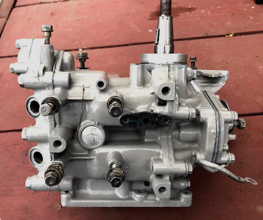 |
I also purchased and installed a self contained hour meter that attaches to a spark plug wire, which was screwed to a thin aluminum plate that was bolted under the top thermostat bolt. A simple and clean installation, readily readable, and out of the way.
| Here, the rebuilt-assembled powerhead installed on the rest of the motor. Notice the new coils & hour meter. |
 |
Also, as a side note, IF you do not get any spark after assembly, you could have possibly assembled the coils in the wrong location, (like the top one on the bottom).
Now with all this repairs, (and virtually a new motor) it seemed fitting to give her a new paint job, including new decals, as this motor had sat out in the weather (a salt air environment) on the back of a 14' aluminum boat for so many years that it faded considerably. During this time, a small tree was growing out of between the seat cushion and it's back.
| Here you see the before | Here are the after |
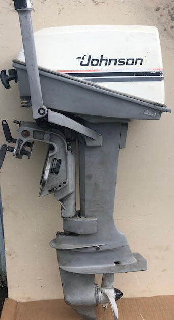 |
Copyright © 2011 - 2022 LeeRoy Wisner All Rights Reserved
Back to
the Main Ramblings Page
Originally stated 09-20-2011 Last Updated 07-25-2022