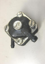
Rebuilding the old OMC Square Fuel Pump
 |
Rebuilding the old OMC Square Fuel Pump
|
 |
The
illustrations below are copied off OMC's fuel pump repair kit instructions #393088
but will also be applicable to the Sierra or NAPA #18-7823 kit
The instructions here are not mine, but OMC's
This same basic fuel pump was used on many motors from made from 1959 thru about
1987
for 2.5 hp up to 40 hp
NOTE-- THESE ARE A PITA TO GET RIGHT THE FIRST TIME & MAYBE EVEN THE SECOND TIME
AROUND, SO IF OR WHEN YOU DECIDE TO GO INSIDE YOUR PUMP BE VERY OBSERVANT.
THE NUMBER ONE THING TO DO IS TO ONLY REMOVE THE TWO
HORIZONTAL SCREWS WHEN REMOVING THIS FUEL PUMP FROM THE MOTOR.
REMOVING THE OTHER TWO ALLOWS THE WHOLE SHEBANG TO COME APART & YOU WILL NOT
THEN KNOW WHERE THOSE SMALL INTERNAL PARTS CAME FROM.
NOTE --
These 8 illustrations are
from scanned pages from the original repair kit.
 |
|||||||||||||||||||||||||||||||||||||||
|
Preface Call out NUMBERS (1), (2), etc. in the text and illustrations refer ONLY to the specific items in the Contents of the Kit illustrations and list. Call out LETTERS (A), (B), etc. are used over & over - on different items in other illustrations. Before disassembly, draw out arrows on your unit indicating UP when the unit is mounted on the motor. Also draw in the position of the fuel pump inlet fitting (A), the outlet fitting (B) and the assembly screws (C), relative to the wide valve body tab (D). Note some early units do not have this moulded in body tab. This sketch will later be used to reassemble the pump correctly. |
|||||||||||||||||||||||||||||||||||||||
 |
|||||||||||||||||||||||||||||||||||||||
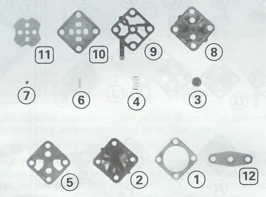
Contents of the kit
Clean the pump exterior and work on a clean bench to avoid pump malfunctions caused by dirt. A word of caution, use a large clean paper or cardboard as some of these springs and other parts are small & tend to disappear. |
|||||||||||||||||||||||||||||||||||||||
|
|||||||||||||||||||||||||||||||||||||||
|
Fuel Pump Servicing (4) remove and place each piece on your clean bench, as it was positioned on your pump. Some may be slightly different than in this illustration. (A) Filter Cap
Assembly
(J) Air-dome Spring (5) Carefully remove the filter screen
(R) or blow solvent and air back thru screen and inlet (S) in filter
cap. |
|||||||||||||||||||||||||||||||||||||||
 |
|||||||||||||||||||||||||||||||||||||||
|
NOTE -- Some parts in this kit must be installed in an exact position or must be installed in an exact relationship to other parts, or the pump will not work. Other parts must be installed in a certain position to fit hoses, etc. on your motor. (7) Place the pump diaphragm (2) on the base gasket. The assembly will be easier if two screws (C) or nails, are inserted up thru the pump mounting holes. (8) Place the diaphragm support (3) in the center of the diaphragm spring (4) on the diaphragm support. |
|||||||||||||||||||||||||||||||||||||||
 |
|||||||||||||||||||||||||||||||||||||||
|
(9) (10) Place the valve housing (A) on the diaphragm spring, with the spring fitting into the recess (B). The two valve housing tabs (C) must be UP (as they are on your motor) and the two drain holes (D) must be DOWN. (11) Place the valve housing gasket (5) on the valve housing with the gasket cutouts (E) aligned with the air-dome spring cavities. The position of the outlet ((B) Fig. 1) on your motor determines the location of the air dome spring (6) and the air-dome support (7) on the valve housing. |
|||||||||||||||||||||||||||||||||||||||
 |
|||||||||||||||||||||||||||||||||||||||
|
(12) If the outlet housing was in position (A) or (B), the spring and the support must be in cavity (C) (13) if the outlet housing was in position (D) or (E), the spring and support must be in cavity (F). (14) Install the air-dome spring(6)
and the air-dome support (7) in the correct position (C) or (F) (16) Install the outlet housing
(9) where the original outlet housing (8) Fig. 1 was positioned, which
is the position used to determine the spring and support location. |
|||||||||||||||||||||||||||||||||||||||
 |
|||||||||||||||||||||||||||||||||||||||
|
(18) Reinstall the cover with the stamped letter "U" to the outside. Turn the cover so the tab on the cover (A) is next to the tab (B) ON YOUR HOUSING. These two tabs must be together or the pump will not work. (19) Check to see that the main diaphragm spring and theair-dome spring have not moved out of position. Reinstall the assembly screws (C) or (D) ( (C) in Fig. 1). (20) Install the filter gasket (11) with the smaller cutouts next to the assembly screws. (21) Reinstall the filter cap assembly in the original position (A) in Fig. 1. (22) Check that the tab (E) on the cover is in line with the tab on the outlet housing (9), and is in line with one of the tabs (F) on the valve housing. |
|||||||||||||||||||||||||||||||||||||||
 |
|||||||||||||||||||||||||||||||||||||||
|
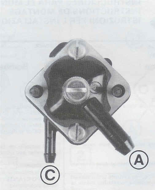
Fuel Pump Test (23) You SHOULD be able to blow thru the pump by blowing into inlet (A). You should NOT be able to blow thru the pump by blowing into outlet (C). If the pump does not pass this test, disassemble pump and check the parts that must be in an exact position or must be in an exact relationship to other parts. After pump is installed, squeeze primer bulb until firm. Check pump and connections for leaks. Correct any leaks before operating motor. |
| This is not a factory photo, but shows the positions of the related parts |
 |
These repair kits are not listed for any pre 1981 fuel pumps even though they are the same. The difference is that the later bodies have projections cast in the metal that matches the tabs on the diaphragms. This is to ensure the parts go back together right. You can do the same by making a felt marker stripe across the metal on one side before you take it apart to ensure you have it back together right.
You can see from the above factory information that IF you need to change the location of the outlet to clear say the terminal block of a electric start motor, that it is possible, BUT follow the placement of the parts.
The reason I mention at the top of this article that it is a PITA to get it back together right the first time, is that while holding everything together AND trying to keep the springs and their supports in position (the small spring tends to flop over on final reassembly). TEST THE REBUILT PUMP AS IN #23. To keep the springs and their supports in position, you may consider placing a dab of Vaseline on the both the spring's tail and the head of the support just prior to reassembly. This can hold them in position long enough to get the other parts aligned and yet not hinder the final operation of the fuel pump.
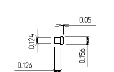
Now for those of you who loose that #7 (Air Dome Support), or plunger to many of us, here are the dimensions. This drawing is small enough that you may not be able to distinguish the radius corners on the large diameter of the outer head. However possibly a shortened 1/8" Pop-Rivet could be improvised to function.
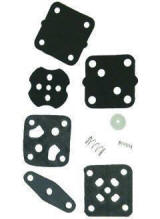
The OMC repair kit #0393088, and the Sierra Kit #18-7823 have all the internals including the small springs and air dome support.
Red-Neck Repairs ; If you can not find a repair kit or diaphragm, look around for a material so you can make your own replacement by copying off the original. One thing that appears may work is find someone who is on a stomach feeding tube using a gravity feeding bag. They have to use a different bag every day so throw them away, and I have found that the sides of this bag is near the thickness of most of these diaphragms AND seem to be gasoline tolerant from the minimal tests that I have ran.
| OMC square fuel pump, air dome support dimensions |
 |
Tips On Rebuilding ;
Rebuilding a OMC fuel pump can be intimidating. And I will say that if you
get it right the first time, you are smarter than the average bear, OR you got
lucky. One thing that may help is OBSERVE how
it came off your motor. Like what part was UP and where the outlet
nipple is located. I suggest that you also mark one side of this body with
a felt marking pen, so you can identify which part went where. I challenge
you to remember these positions otherwise !!!!
OK, after fighting trying to repair a OMC fuel pump using a OMC repair kit, and
having lots of FRUSTATIONS, (ONE HELL OF A TIME trying to get the plunger
spring/dome to stay in place on final assembly). I developed a fixture and
a procedure on how I now do this job.
The
factory directions say to use some screws to align the parts, but believe me,
there had to be a better way.
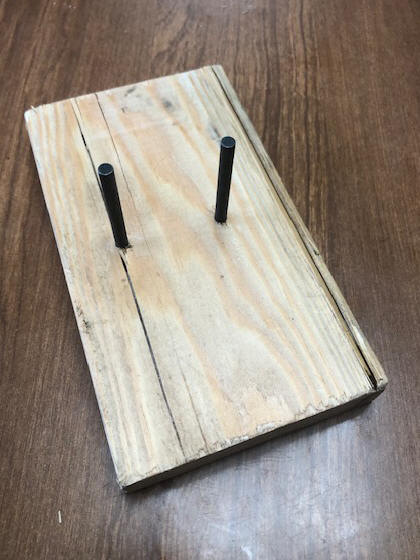
I use a base to mount it on, using a 3/4" X 4" X 6" wood board. In
this I install (2) 3/16" smooth rods to match the same holes on the pump body to
the motor (1.50" apart). What I found was 3/16" X 2" rivet (no threads).
These need to be longer than the assembled pump by maybe 3/8". To achieve
this length, I countersunk the heads by about 3/8", then epoxied the heads in
the holes. They are essential alignment studs. NOTE - the photo
below has an optical illusion as the studs are parallel.
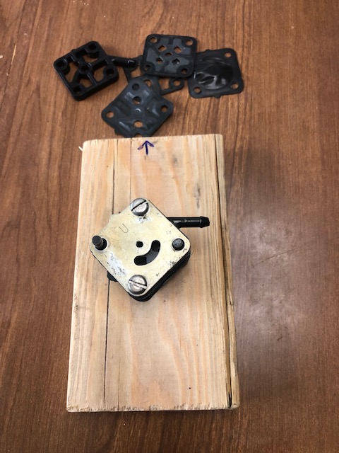
One suggestion here though, is to initually place your existing fuel pump on these guide pins and using a piece of masking tape on this block, and mark the location/direction of the outlet nipple.
| OMC square fuel pump, rebuild fixture block | OMC square fuel pump, fixture block in use, with some old parts shown |
 |
 |
You will find it beneficial
to have on hand a set of tweezers, for placement of the spring and plunger.
In doing the final assembly of the spring and plunger dome, first using a
toothpick and add a small dab of Vaseline on one end of the spring, and onto the
"Tail" of the plunger as something to temporarily retain the them. These
can now be CAREFULLY aligned in the desired location. I said CAREFULLY, as
they have been known to have had flying lessons in the past and seem to be able
to remember their instructions.
Carefully align all these components (USING THE FACTORY ILLUSTRATED LIST).
Now compress the metal cover and install the two screws.
You will notice the arrow on this fixture, this is because on the factory instructions, it references the UP position.
| OMC square fuel pump repair kit #0393088 |
 |
When finished, you can test
it by BLOWING on the metal cover moon shaped opening. It may take a lot of
pressure, but you should be able to blow in, but not suck out. Then do the same
on the outlet nipple, here you will be able to suck out, but not blow in.
Just because your motor may be running, IF IT HAS CONSIDERABLE AGE ON IT, it may
be best to replace, or rebuild the fuel pump, as over time (especially if it has
not been running fore some time) the diaphragm will loose it's
flexibility and get stretched, loosing it's capacity to fully be operational,
thereby creating issues where you may seem to be chasing your tail.
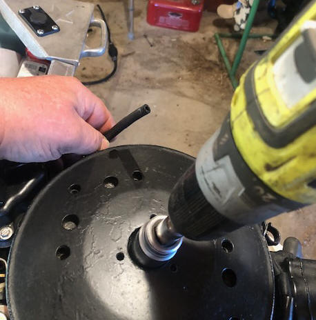
The method that I have found to test one of these, is to remove spark plugs, remove the fuel line at the carburetor, using the fuel line primer bulb pump the line until you get fuel coming out that line. Now, using a drill motor with a socket to match the flywheel nut, rotate the motor and watch how much flow you get out of this output line. If you just get sputters and not more of a volume on each stroke, maybe the pump is not working at capacity.
| Here is my method of testing |
 |
Originated 11-06-05 & last updated 09-06-2023
Contact the author