|
|
Maintaining Johnson QD / Evinrude /Sportsman
1949 – 1963 (Information & normal repairs) |
|
Johnson, Evinrude, OMC, outboard motor, outboard motor repair, 9.5 hp, date/year of manufacture, water pump, carburetor,
|
|
Maintaining Johnson QD / Evinrude /Sportsman
1949 – 1963 (Information & normal repairs) |
|
The early Johnson motors appeared on the market about 7 years
(1949 to 1955)
before the
Evinrudes, were probably true Johnsons, and in 1956 Evinrude's engineering made
some major changes, (like reworking and getting some bugs out) which then pretty
well carried on for the rest of the production years.
Those made from 1958 as shown in the LH photo above utilizing a
"suitcase" motor cowling. And then the
later style 1959 to 1963 which utilized a more modern cowling as shown in the RH
photo. The throttle advance was also changed from the initial timing plate
cam to the more now common twist grip throttle. Other than that, it appears that the main motor and everything but the cowling is
the same. The cowling for 1960 and 61 had a gold raised ring on top like
the photo on the upper right of this header. In 1959 the lower unit
was downsized, getting away from the gearbox it had shared with the 15hp.
And from 1960 on, the motor was fitted with a fuel pump instead of the
intake manifold pressurized tank with Siamese hoses as were used previously. So
many changes
were made as time went by.
There was a dramatic change
in them from the inception (1949) and the second version in 1956. The
early motors utilized the magneto system off the earlier 5hp TN series, and the
timing plate mounted throttle advance. The driveshaft/water pump was also different.
Also the motor mounts were not as robust as the later vesions.
| Here a 1951 Johnson QD-12, NOTE the 2 piece horizontal top cowling & the non twist grip throttle | Here a 1957 Johnson QD-18, NOTE the 2 piece vertical hinged (in the middle) top cowling |
 |
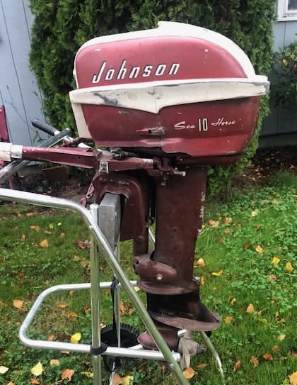 |
Later there was a companion 15 and 18 hp motors made at about the same time as the early QD with a model FD which was very similar and also shared many parts.
The year of manufacture for these models of motors are listed in the chart below. Apparently for Johnson, the first four years of production model numbers did not stop at the calendar year end. It also appears that the long-shaft motors were not made until 1957 after OMC was formed a year earlier. The "L" in the model number designates it being a Long Shaft.
There should be the model and serial number on riveted on 1” X 2” aluminum ID plate on the LH side of the transom mount bracket (looking forward).
Another bit of information for Johnsons, if the ID plate is missing is use the color of the engine, which may help as to closely ID the year, 1949 - 55 metallic Green, 1956 - 58 metallic Red, 1959 - 63 White. Evinrude pretty well stayed to the deep blue color, and later white trim.
The Evinrudes did not totally parallel the Johnson line as I can find no evidence that 10 hp Evinrudes (of this model) were made prior to 1956. They were named the Sportwin. In 1959 they produced the Golden Jubilee model with a new style fiberglass cowling and special insignia.
In the table below, for Evinrude, the second model number was for a 5' longer shaft length. As mentioned above, for the Johnson, they added a letter "L" for their long shaft version.
| Evinrude Johnson | |||
| Year | Model | Year | Model |
| 1949-50 | QD-10 QD-11 | ||
| 1951-52 | QD-12 QD-13 | ||
| 1953 | QD-14 | ||
| 1954 | QD-15 | ||
| 1955 | QD-16 | ||
| 1956 | 10012 / 10013 | 1956 | QD-17 |
| 1957 | 10014 / 10015 | 1957 | QD-QDL-18 |
| 1958 | 10016 / 10017 | 1958 | QD-QDL-19 |
| 1959 | 10018 / 10019 | 1959 | QD-QDL-20 |
| 1960 | 10020 / 10021 | 1960 | QD-QDL-21 |
| 1961 | 10022 / 10023 | 1961 | QD-QDL-22 |
| 1962 | 10024 / 10025 | 1962 | QD-QDL-23 |
| 1963 | 10302 / 10303 | 1963 | QD-QDL-24 |
Statistics For These Motors :
These motors are 2 cycle, water cooled, and develop 10 hp @ 4500 RPM
Cylinders
2
Bore diameter
2.375"
Stroke
1.875"
Displacement 16.6 CI
Starter - Automatic rewind
Bearings, - Needle
bearings for all mains, but not on early rods
Carburetor - Johnson Tillotson type with choke, throat dia. .612" - Carb kit
Sierra 18-7043
High speed jet - adjustable up until 1963, Starting point
3/4 turn out
Idle jet - 1 1/2 turns out as a starting point
Fuel capacity - Remote tank
6 gallon pressurized
Siamese hose from inception until 1959, fuel pump single hose
after that
Fuel mix - is Oil 1/3 pt. (24-1) SAE-40 per Gal
for early motors (from1949 to
1957) 50-1 for later motors
Point gap is - .020"
Plug gap .035"- Champion J4J or J6C spark plug.
Flywheel key - Woodruff .154" (5/32") wide x .235" thick x .603" long
Flywheel nut - 7/16" NF, -- 11/16" wrench size
Water Cooled - rubber vaned impeller type - Sierra #18-3002
or 18-3003 after 1955
Gearbox oil - 90 W gear oil
Gear Ratio -
15-25 for the 5 bolt & 13-23 for the 4 bolt gearboxes
Prop- 3 Blade 8 1/4" x 8 1/2" RH
Prop Drive Pin - .187" X 1.312" OAL
Prop nut retainer pin
- 1/8" X 1 1/2" cotter pin,
stainless steel
Prop nut -
9/16" X 16 thread, Rubber nose cap
Weight - 67#
I have had the opportunity to be able to work on three of these motors, one, a 1957 Johnson, 1959 Evinrude and the other a 1960 Johnson. The Evinrude will someday be power for my 14' StarCraft aluminum boat.
If you need to check on parts and do not have a actual parts list booklet, one of your best sources is http://www.marineengine.com/parts/parts.html. They have a complete listing of about all of the Johnson and Evinrude motors showing exploded parts views with part numbers. Here you may be able to order parts online from them. Or to Boat info 1922-1964 Johnson Service Manual
Most of these online marine parts houses do not show motors for before 1956 or so, (some even later) if that is the case, just go to the next year (for marineengines.com) it will be 1958. In this case just because they do not show a illustrated diagram for that year does not mean they don't have parts for it. And knowing that this model was not really changed from 1956, a 1958 list should be pretty much the same. Tough luck in finding anything for the pre 56 models,
Go to your local NAPA automotive store. They have a marine products catalog that shows #18-5181 replacement coil that is supposed to fit 1949-1963 10hp Johnson. Looking farther, it is a pretty standard coil that fits many other motors from 1.5hp up to 30hp. They also show points and condensers. The tune-up kit (the whole set of 2 points and 2 condensers) is #18-5006. If your local NAPA store is unresponsive to your needs, then use their part number and do a online search.
You will not find many aftermarket internal parts for these motors in the NAPA or Sierra catalogs apparently as this motor dates too far back. Here is a link to a website that has considerable info on these old motors CLICK HERE
Recommended Fuel / Oil Mix : Information on these old 10 hp built from1949 to 1957 is sketchy as to if they were built with needle bearings in the crank but not on the rods, (later ones, at least from 1958 were for sure). This is what governs the fuel/oil mix on all these older OMC motors. Needle bearings on the connecting rods will be able to use 50-1 ration. The ones that have bronze rod bearings is 24-1 of the old 30 weight automotive motor oil. Now it would be the TCW-3 standard outboard oil, which would give better oiling and longer motor life than the automotive oil originally recommended for this motor.
On most all of the pints and quart plastic bottles of TWC-3 oils there will be a narrow clear vertical window on the edge of the bottles. On the sides of this window will have numbers representing ounces and Milliliters for other parts of the world. Or you can purchase special measuring containers showing different ratios and the amount of ounces needed.
These are one of those motors where you have to mix the oil with the gasoline, so you need to know how much gas you will be needing, add the oil before you fill the fuel tank so that the oil mixes better that just dumping it in after you fuel up. However if that is not possible, then guess, add a majority of what you think it will take, top off the tank and then add the rest matching the amount of gasoline you took on. If you are using portable fuel thanks, before hand, when you fill it, add 1 gallon at a time, use a clean 3/8" or 1/2" dowel start filling the tank, mark the dowel at each gallon you add, then you can use it as a measuring stick. This way you can refill a partly full tank with the known amount of oil.
A quart has 32 ounces of oil in it.
|
FUEL MIXING TABLE |
|||||
| Gallons of Gasoline |
Gasoline to Oil Ratio |
||||
|
Ounces of Oil to be Added |
|||||
| 16:1 | 24:1 | 32:1 | 50:1 | 100:1 | |
| 1 | 8 | 5 | 4 | 3 | 2 |
| 2 | 16 | 11 | 8 | 5 | 3 |
| 3 | 24 | 16 | 12 | 8 | 4 |
| 4 | 32 | 21 | 16 | 11 | 6 |
| 5 | 40 | 27 | 20 | 13 | 7 |
| 6 | 48 | 32 | 24 | 16 | 8 |
Now the recommended fuel is 87 octane
gasoline. Early on for the 2 cycle motors the recommended oil was regular
automotive 30 weight motor oil, then the outboard industry came up with any TWC
oil, which finally evolved through 1 and 2 into the latest which is TWC-3 outboard motor oil. You probably will not see much of the older TWC-2
oil out there anymore. You can spend your money and purchase OMC
oil for about $6.50 a quart, or buy a name brand quart for $3.59. Sure the manufacturers want you to buy their
oil, and for a new motor under warranty, it may be advisable to do so. But the consensus from many experienced boaters is to use any good brand of oil, as long as it has the TWC-3 rating, it meets or exceeds the manufacturers
specifications. The TWC-3 represents,
Two cycle,
Water
Cooled, type
3
formula. The formula 3 has
decarbonizing additives
designed to be more compatible with the newer non-leaded fuel.
So from the above information, you can see that fuel and oils have changed dramatically since these motors were first brought out. In this instance, times have changed for the good, as we now have a better gasoline along with way better outboard oils.
DO NOT use oil designed for your weed whacker or chain saws as these air cooled motors run a lot hotter than the water cooled outboards. The outboards require the specially designed TWC-3 oils.
| Here is an example of a early QD crankshaft that showing what can & does happen if the oil mix is too lean. More like probably here, there was no oil mix in the fuel at all |
|
|
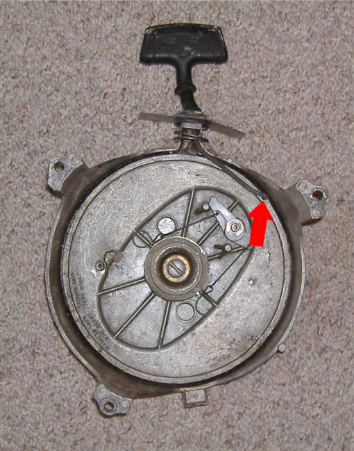
Recoil Starter : These motors have a recoil starter mounted on top over the flywheel that is bolted to the block by two bolts in the front sides and one in the rear. The starter pawl is attached to the rope spool by a couple of unique springs that are activated as the rope is initially pulled as seen in the photo below. The spool is held into the housing by a single bolt in the middle coming up from the bottom. The rope appears to be 9/32 diameter, however the smaller 1/8" could be used.
The spring usually has a long life. However if it breaks, it is pretty straight forward in replacing it. Sometimes if a spring breaks and has broken a few inches off, you can heat the end up with a propane torch, enough to make a new bend, which may work OK. Replacement springs are still sold, factory # 0395460 or Sierra # 18-6501.
A trick that is often used to modify the spool for ease of replacing the rope, is take a Dremel tool and grind a shallow groove on the lower lip of the starter spool, as seen by the red arrow below (any location will do and will vary depending on the length of the rope). Grind just enough to allow the rope to be pulled into this groove and then be rotated around between it and the housing. To wind the spring tighter, pull the rope out a couple of feet, rotating the spool to where this groove is in line with the rope exit hole to the knob. Reach in with a small screwdriver or crochet hook, pull the rope out and into this groove. Now you can pull the rope more, winding the spool tighter with this rope secured in the groove, which allows you to add spring tension easily without jumping through hoops of getting things right before you bolt it back onto the housing.
I do read "arrow here rope recoiled " and below that model numbers of JE or F. Since I do not have a service manual for this motor, I am not really sure what that means.
| Rope pulled into hand ground groove to facilitate winding rope onto spool |
 |
| Left side showing throttle linkage | Right side of the 1960 motor showing manual starter, carburetor, air breather, old style fuel pump & shifting lock-out directly in front of the fuel pump |
|
|
|
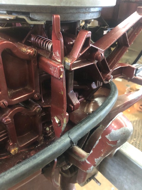
This lock-out is designed so that it will allow a minimal speed if in Neutral, Forward or Reverse on starting. But in Reverse a limited medium RPM, and in Forward a full RPM. This is so that you cannot put the motor into a HIGH speed reverse, which may be dangerous.
| Here is a better view of the shifting lock-out on a QD-18 |
 |
There appears to be no provision for electric start on these motors.
Flywheel : As for removing the flywheel, unless it is rusted on, loosen the nut a few turns so it protrudes slightly above and protecting the crankshaft threads, wrap your arm around the flywheel, putting tension (raising the motor), rap the nut sharply with a 2 or 3# hammer, (brass preferably). The weight of the motor hanging by the flywheel will usually allow the flywheel to pop off the taper.
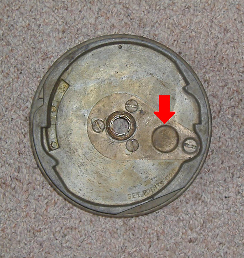
The only markings I find on the flywheels are " set point .020".
This flywheel has a inspection cover that allows you to go through the hole to adjust the points without removing the flywheel, as seen at the red arrow below. This cover is held in place by three screws that also serve as flywheel puller attachment holes. There is another screw holding the outer edge in place. The flywheel nut is independent of this cover plate.
You will notice the two large hook type dog teeth, which is where the starter pawl engages.
| Top view of flywheel | Bottom side of flywheel |
 |
|
Ignition : This later series of motors used a magneto ignition system with points and condenser ignition which shared common parts with many of the other Johnson motors of the same era. The coils, especially those in the 60's motors have a reputation for cracking and allowing moisture in and then starting to break down, creating problems. They changed the plastic formulation on the coils at some stage and the replacement ones are fine. About 60% of the old motors I have had needed one or more coils replacing, and would be financially unviable for someone not working on their own motor.
If the coils are a red
color, then they are old factory and probably not good. They are usually the 1st
thing that go in these old motors. Look for cracks in the plastic covers
on coils. If they are cracked and swollen, then they are junk. If
the coils are green or black, then they have already been changed and will last
another 50 years.
A lot of people will
replace the coils without replacing the spark plug leads. Even if they do,
often times the connection from the coil to the spark plug lead is not very
good. The faces of the coils also have to be lined up with the machined
face perfectly or you're spark will not be perfect. Those who run the old
spark plug leads after changing the coils will often overlook the spark plug
boot connections also.
To adjust the points most versions have a "inspection hole" in the top of
the flywheel, if so you do not have to remove the flywheel but can adjust
the points thru this hole. If you do need to replace the points, you will
need to remove the flywheel however. On some of these models
(especially the early ones) they may have a spring loaded cam on the crank
shaft. Or with the flywheel off, remove spring to install or set the
points then use a thin screwdriver to hold the cam down while putting the
flywheel 'mostly' on. On these if you do
take the flywheel off, you may find it hard to get the flywheel back on
because it is hard to get this cam to stay down while
reinstalling the flywheel. (1) Use screwdriver to hold the cam down
while putting the flywheel on, and if you're quick, it works. You may wish
you have an extra set of hands though, or call a buddy over. (2) Or turn
the shaft/cam to where it is just short of starting to open one set of points.
Then the cam will slide down without interference. Now your ready to
torque it on. Not too bad once you get the hang of it.
One old time mechanic had a suggestion. If you are setting the points with the flywheel off, you may find that holding this cam down while setting the points is a bother. You can made a short piece of tubing to hold the cam down while setting the points. The flywheel nut holds the tubing down, tubing holds the cam down.
Double check your points gap, .020, anything more or less may throw timing off enough not to fire. These need to be set at the highest part of the cam lobes (usually where the keyway is located) and if off just a slight bit it can effect timing. However if you are setting them through the inspection hole, you have no choice, as this flywheel hole is positioned in the correct location when you are setting the points.
| Timing plate showing ignition system & one bad coil |
|
|
In the photo below you can see the
burned out coil from the above photo. Replacement ignition parts are
still available by the factory or aftermarket at Sierra. They will
run, but do not have a lot of power if on only one cylinder.
| Burned out coil |
|
|
When troubleshooting a
new motor to you, initially you will want to check compression, and next
spark. On the 1957 that I worked on, compression was 97# on
#1, with 95# on #2 (VERY GOOD), which may even come up a bit after it
has been ran. However it only had minimal spark on #1 and nothing
on #2, After cleaning, reinstalling and readjusting the points, I had fire on
both cylinders.
One thing
if you have removed the spark plugs but forgot which plug wire went to
which cylinder, wrapped around the top spark plug wire is a aluminum ring
crimped onto the wire, with the word TOP.
OK next would be to see if it would run, so by spraying a couple of squirts of starting fluid into the intake manifold, IT FIRED and ran for maybe 10 seconds. BINGO, things are looking up, as I now know it has all the possibilities of running. Now to look into possibly replacing the old Siamese fuel line, the old gas tank still has some gas in it and the internals look clean.
Then remove and soak the carburetor in carb cleaner overnight, and reassemble it, just because -- why go only part way? Fast Forward -- when stripping down this carburetor, it was amazingly clean on the inside. Then the final look would be at the water pump impeller and check/replace the gearbox lube oil.
Kill Button : There is no kill button on the early models, just a note on the front panel to choke it to kill it. For the later versions, a button is mounted in the lower front cowling on the right hand side.
| Kill button shown on the exterior with the actual sealed connections inside |
|
|
Recommended Spark Plugs : The recommended spark plug is a Champion J6J, now J6C, however with a well used motor most old time mechanics would recommend a hotter plug, like the J4C especially if you do a lot of trolling. Or if you opt for the NGK brand, go for BR6S-8. These plugs use the 3/8" reach, so do not try to use the 1/2" reach ones off the 9.9hp as the electrodes will become smashed by the top of the piston.
Twist Grip Throttle Handle : The later twist grip and throttle uses cog gears similar to the commonly seen other series motors. This shaft needs to be lubricated more than occasionally.
Low Speed Stop Screw : These motors (at least the post 59 models) have an adjustable stop screw on the bottom gear at the end of the rod that moves the advance mechanism (base of the handle).
| This adjustable stop screw shown at the arrow can be adjusted to bump against the boss in front of it |
|
|
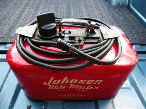
Fuel Pump : The early motors used a dual (Siamese) fuel line from a 6 gallon pressurized tank. Here there is a line leading from the intake manifold and by using the 2 cycle principle of operation, once the fuel tank was pressurized (by a knob) on the motor itself, would re-pressurize the tank, which would pump fuel back in the other line into the carburetor. All these 10hp motors made prior to 1960 would have had the older pressurized Siamese type dual fuel line. When these work, they are surprisingly effacement, but with dual lines, you run the chance of more possible leaks. If you are having problems and the indications point to fuel, double check the fuel lines, or fittings/tank for leaks. These tanks do not have the quick coupler on the tanks, just the hose crimped onto barbs on the tank fitting.
| Old style pressure tank, note the pump knob on the right. |
 |
On the late motor that I had access to for this article (a 1960 version) had the
fuel pump bolted to the top by-pass cover which used the standard single hose fuel
line. The larger 35hp and the Fat Fifty was really the only motors
that had separate fuel pumps up to and including 1959. Everything
else was pretty much all pressure tank models. HOWEVER, a fuel pump kit was offered as
an accessory on the 10hp and up motors as it would be needed for boats with built-in
fuel tanks.
The older tanks are dual line pressurized, while the newer single line tanks operate on a vacuum. Meaning on the older tanks, the cap has to be tight, where the later tanks, the cap has to be vented. However the OMC metal vacuum tank caps have a built in vent system in the cap or fuel line connector, where the aftermarket ones usually have a screw in the center of the cap which needs to be lightly loosened, forming the vent.
| 1960 fuel pump side view | 1960 fuel pump rear view showing by-pass cover |
|
|
|
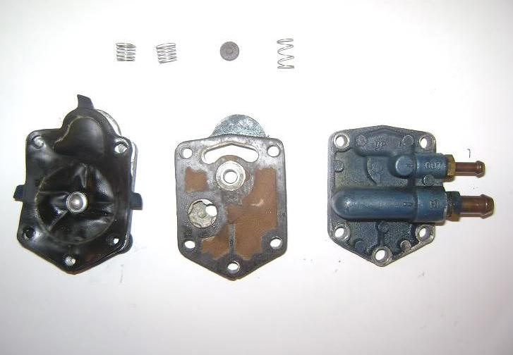
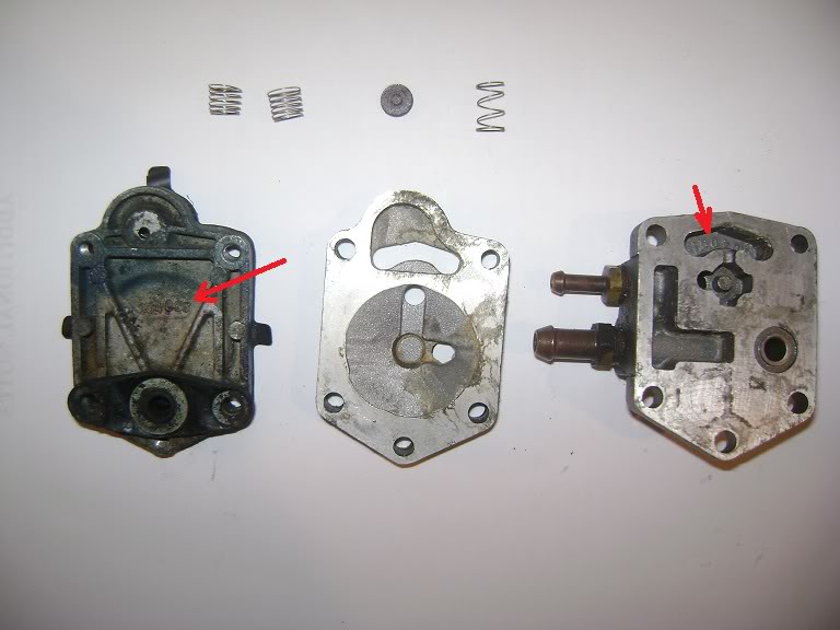
| Here is the original fuel pump disassembled | Here is the same fuel pump but the parts flopped over |
 |
 |
The fuel filter/sediment bowel does not really need to be
there, but since it was already mounted, I just left it, re-routed the fuel
lines to and from it.
To convert the older motors to a
fuel pump here is a
LINK on how I did one.
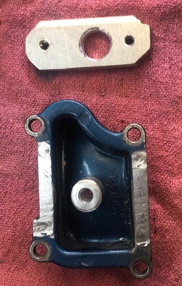
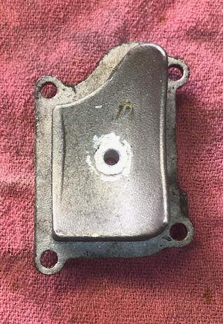
Or as I have done on this 1959 motor. Here I made the 1/4" adapter plate,
using a new fuel pump gasket as a pattern. The threaded holes are tapped
10-24 with the center hole 3/16". The connector is a piece of aluminum rod
threaded to 7/16" X 20 NF and the cover drilled and tapped to accept the rod.
The plate was then drilled to accept the center connecting rod. The inside
is concaved, so the inner part of the rod was fitted to the inner contour.
The plate was installed and Heli-Arc welded to the plate and the rod.
Then the weld was sanded down to match the plate surface.
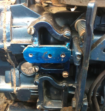
You will notice on the LH photo the adapter plate is offset to the rear. This is because on this motor there is a neutral no start lever that is very close to the front of the cover. The only thing to modify was the thick fuel pump gasket and relieve a channel at the rear center of this adapter so there was no obstruction at the gasket.
| 1959 bypass cover being converted to use for a fuel pump | Here the inside of the bypass cover seen on the left |
 |
 |
| Here the finished fuel pump adapter | Here the fuel pump unit mounted on the motor |
 |
|
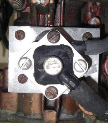
Another Method : If you can not find one of the newer bypass covers, one can be made from a piece of 3/16" aluminum as shown below, which allows you to convert over to the newer small square 1965-1985ish fuel pumps. However my question is, the original covers have internal concave configuration for better fuel flow. if you made this simple plate conversion, do you contribute to different fuel flow to the top cylinder.
| Here is made up an aluminum adapter plate for the newer style fuel pump conversion |
 |
Thermostats : These show in the parts manuals to be the same from 5hp to 55hp for years 1959 to 1994 (however not fore the 9.9 or 15hp). They may have slightly different configurations because of improvements, but they will all function no matter the shape or design. They can usually be removed and cleaned up with no problems, UNLESS they are really contaminated because of debris or salt corrosion. Do not run outboard motors without a thermostat. They should open at 143 degrees. This can be tested by boiling them in a pan of hot water, while using a cooking thermometer then watch to see if they open near the right temperature. If this internally operated valve does not move, it usually cannot be revived.
| Here the thermostat cover is removed showing the thermostat on the top LH side of the head |
|
|
Oil Tube for Top Main Bearing : There is a brass tube located on the LH side of the block at the juncture of the intake manifold to the block. It transports oil from the bottom to the top main bearing. All of the fuel that the motor burns passes through the crankcase on it's way to the cylinders. This oily fuel is what lubricates the internal parts. Most of it goes right through, carried along with the airflow to the cylinders. But a bit of it "rains" out or splatters up against the walls then drains down settling at the lower main bearing. There is collection pocket around this lower bearing housing. This oil collected in the bottom pocket is pumped to the top main bearing by the alternating suction/pressure of the action of the 2 cycle operation. It is all accomplished by taking advantage of the different pressures in the crankcase. There is no mechanical pump like what you would find in a four-stroke.
| The oil transfer tube is shown here by the screwdriver on the port side of the motor |
|
|
No Overboard Water Indicator : These motors were made before the common "pee hole" indicator became common. There was just a "blubber hole" on the rear upper exhaust housing where some of the exhaust gasses mixed with some of the used cooling water from the engine.
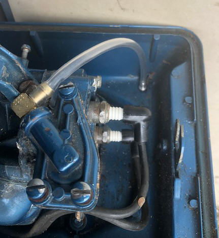
On this 59 Evinrude, I converted it to a overboard water indicator (pee hole) by tapping into the thermostat cover. Here there was just enough room off the plugged end of the cover to tap it out to 1/8" pipe threads and then thread in a brass Ell with 3/16" a barb. The outlet tip was lathe turned out of aluminum, with a flange as a stopper and the outlet itself, just big enough to go through the existing lower pan drain hole. By using 3/16'" vinyl tubing and heating it with a heat gun to soften the ends, I got a tight fitting. This way, no permanent modifications were made.
| There you see the modified thermostat cover with an 1/8" pipe Ell for the hose connection |
 |
Carburetor : These carburetors have both high speed and idle jets that are adjustable. In the photos below of the pre 1959 version there is are individual separated knobs for for both the high speed and low speed adjustments placed vertically on the front cowling with the choke on the Port side.
| Here a QD-19 (1958) shown from the rear with the breather boxes. Note the fuel filter on the bottom of the carburetor | Here the same QD-19 showing the front panel with separate high speed & low speed knobs |
|
|
|
The front motor panel of this later 1960 version shown below has a dual knob in the center. The outer knob is the high speed adjustment which is marked from 1 to 6. The (supposed to be red) inner knob is the idle adjustment. The choke is in the normal Starboard side of this panel.
The timing plate cam on this version angles downward as it extends to fast position. The cam roller is mounted on the front of the intake manifold, (shown in the photo below) instead of on the carburetor tops like the later ones are.
The basic carburetor is pretty much the same, for the pre-and post 59s but the linkage is different.
| Front view showing timing cam & roller | Control panel for a post 59 Johnson motor showing both high & low speed jet adjustments with the choke knob on the left |
|
|
These carburetors have a built in glass fuel filter / settling bowl at the bottom. The air breather, (they call it the air box) is attached to the front of the carburetor. The choke knob is screwed onto the brass linkage rod from the front. The nuts holding the carburetor onto the manifold are 5/16" and use a 1/2" wrench. You have to pull the choke out to access the RH nut with the wrench.
When you take it
apart, it is advisable to count the outward revolutions of both of these
needle jet shafts so you have an idea as to were to return them to.
These floats are made of varnished cork. Unless the motor has been
stored with old gas in the carburetor, the float should still be usable.
The float level is set so the float is parallel with the body when turned
upside down. This is done by bending the brass tab at the rear of the
needle for the shut off.
In cleaning up the 1957
motor, the carb was darned clean, BUT the cork Low Speed Nozzle Gasket had
hardened enough to not survive being reused. The newer repair kits
have a Neoprene gasket #0344037 at a price of $6.41 if sold separately.
However a plumbing Neoprene flat washer #3/8M (which is about .112" thick) can
be modified by drilling a larger hole in the center .243" then treading it
onto the needle shaft, and rotating it on a course sanding belt to achieve a
diameter of from between 7/16" and 1/2" OD.
One
suggestion, when removing these carbs, take a photo of the spring tension
system around the low and high speed needles. These put tension on
the Johnson front panel. However do not take it as being totally
correct, (like some DIY mechanic) may not have replaced them correctly.
But anything is better than trying to decipher what goes where off a exploded
part diagram.
ANOTHER thought, if the motor is having starting problems, these motors won't start if the high speed needle is adjusted wrong. When turned to the start position for cold start it's the high speed part of the carburetor that comes into play here, not the low. Also make sure your needle stem packing is new for both, and that the main jet is backed out enough for it to fire as described below.
In the photos below you can see the bottom or high speed jet along with it's linkage to the control knob. The knob operating this jet slides over a octagon sleeve around the idle jet shaft. The low speed needle which is the top one, screw it in to a lightly seated position and back out 1 1/2 turns. The high speed needle which is the bottom one is 3/4 turn out from lightly seated position. Run it in gear under load (at a fast run), adjust high speed in until it starts to die then back out until it runs smooth. Slow down to idle and adjust low speed in until it slows down or starts to cough and back off until it smoothens out. You can loosen the high speed linkage rod and adjust the linkage so that the dial is set where you want it. I also like to slip the low sped knob onto the shaft so the pointer is pointing straight up. That's all there is to it.
If you are having starting problems, and you are sure the
ignition is OK, fuel or the choke may not be operating properly for cold
start. Spray come mixed fuel into the carburetor and see if she fires
off.
Anyway, it shouldn't take more than 10 minutes to pull the intake manifold and check the
reeds to see if a bug or whatever is blocking them open.
In the photos below you see the close-up of the carburetor and the newer type breather/silencer.
| Right side view of a 59 | Left side view of a 59 |
|
|
|
As this series advanced, the factory made changes, (with this series probably having underwent the most cosmetic surgery of all the other models). The previous models utilized the carburetor dual knob system with center knob as the idle adjustment and the lower knob as the high speed adjustment. As seen in the RH photo below, this is reversed with the high speed in the center. This is because the main motor cowling was changed, putting these adjustment knobs in the lower part of the cowling instead of higher in a separate front panel. Now the high speed adjustment is directly in line with lower needle (high speed), instead of using a linkage rod to activate it.
| Front view of a QD-10 model (1st year) | Front view of a 1963 model |
 |
 |
Reed Valves : Stuck open reeds will keep the motor from being able to push fuel into the crankcase, thereby preventing it from starting. However, stuck open or closed reeds will have no effect on compression because the compression reading is off the top side of the piston. The reeds open and close, sucking fuel into the crankcase from the carburetor because of the osculating suction/pressure off the bottom side of the pistons.
Many times if they have sat for a number of years, crud/rust may accumulate under the seats of the reed valves. But they're rarely the problem, however if you are pulling the carburetor to clean it, you really should pull the manifold and check the reeds JUST IN CASE.
If it's bad reeds, the motor should still crank up and start momentarily if fuel mix is sprayed directly into the spark plug holes. If you decide to pull the manifold to check the reeds, be very careful if you choose to pull the intake that you remove every screw! There are a couple of hard ones to spot inside the manifold that must be removed before it will come off. If you pry on the manifold with much force you are guaranteed to ruin it. However I wouldn't pull it unless it will start with fuel in the cylinders, but not without it.
Motor Mounts : The rubber motor mounts are pretty well designed, a rubber block with attachment bolts molded into them last a long time and are externally mounted. The actual runner mount is the same for both the upper and lower, but the lower has a housing around it that also clamps onto the pivot shaft as shown in the photos below.
| Upper motor mounts | Lower motor mounts behind the cover |
|
|
|
Upper Cowling Mounts : These rubber mounts are susceptible to breaking, especially the rear ones as the rear of the cowling is what is normally used to help lift the motor up and puts a lot of strain on these rear mounts. These tend to have the bonding from the bolts to the rubber deteriorate and may separate from the mounting bolts. It is also rather hard to remove the usually rusted nuts from the bolt studs to even try to re-bond the rubber. The originals are made of a thick round rubber that has a stud screw bonded to both the top and bottom. If you have the powerhead off, you could make replacement ones from 1/4" all-thread and some thick rubber, about 5/8" (I am guessing here as to get to them it takes pulling the power-head). Otherwise it is probably the best would be to try to clean them and then use Super Glue.
They are usually just left alone unless you are doing are rebuild with the powerhead off. Leaving them broken, the result is not detrimental to the running of the motor, except the upper cowling when snapped to the lower part has some movement and can make a rattling noise when running.
| QD cowling mounts |
|
|
Clamp Bracket Screws : These screws that hold the motor to the boat transom threads are 1/2" X 13 TPI or National Course. If you can not find any replacement ones then a simple 1/2 NC bolt 3" long or with at least 2" of threads and with a flat washer under the threaded end will suffice for a considerable time. It may just not be a pretty looking as the original, but it will hold the motor to the boat. Most of these screws are damaged by neglect of not maintaining them with a small amount of chassis grease or Vaseline before they rust or corrode in the bracket.
Shown in the photo below is a built in location to use a chain from the motor to the boat for safety sake.
| QD clampscrews |
|
|
Shaft Length Change : If you need to change from a short shaft (15") to long shaft (20"), lots of luck in finding the 5" extension required to make this change. Drive-shafts, shifting rods and water tubes can be lengthened the 5", BUT IT IS A HASSLE.
Changing a long shaft to a short shaft would be easier. As you might find a used driveshaft like I did for less that $50 including shipping, and then I can sell the complete long shaft kit to someone who really needs it. Or, just remove the extension, shorten the driveshaft (cut and weld in the middle) and shorten the shifting rod upper part from the gearbox and the water tube from the water pump. FYI short shaft length is 25 1/2".
Welding the driveshaft (either shortening or lengthening) would be best to take it to a machine shop/welder, as afterwards the shaft will need to be straightened in a lathe by slight bending "adjustments" numerous times to get it to run as true as possible. If the welder is hesitant, then have them also make, and slide a stainless steel sleeve over the weld and weld it in place also. Just be sure this weld is up above the water pump and in the exhaust cavity area so it does not interfere with the water pump. The only thing that might interfere is IF it is the version is where the lower drive gear is not splined onto the driveshaft (but pinned), replacing the water pump impeller will require total disassembly of the gearbox as it would need to be assembled differently (if even possible).
Drive-shafts were different on the early motors (QD10s at least). These shafts are 1/2" diameter, and the older ones had 11 splines top and bottom. The later ones used 4 spines to and a woodruff key at the bottom drive gear.
Remove Lower Unit
:
In getting the lower unit (gearbox) off, here is
the procedure.
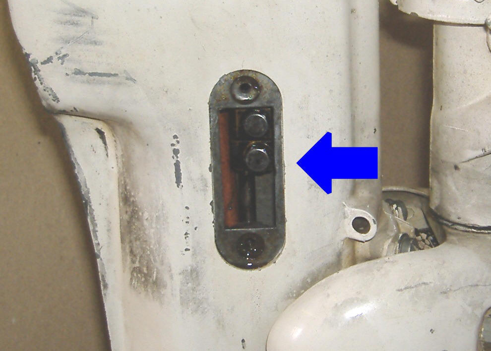
To access the shifting lever coupler when removing the lower unit, there is a small cover on the right hand side of the exhaust housing retained by a screw top and bottom. Remove this cover then you can then get to the coupler and remove the bottom screw to disengage the upper shifting rod from the lower rod in the lower unit. Now the lower unit should drop down and be loose from the rest of the motor.
In replacing this screw upon reassembly be careful to get the groove that the screw goes into centered in the screw hole before you attempt to insert and tighten down the screw. The one I worked on had a tendency to slide up too far which could bind the screw when it was tightened, stripping the threads. A flashlight and slow movement of the shift lever is needed in this situation.
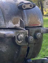
| Access cover in place on the RH side of the mid-section | Access cover removed, showing shifter rod coupler screws |
|
|
 |
Gearbox : If it runs pretty much OK in neutral, but bogs down in any gear, then possibly you have a lower unit / gearbox problem. Unscrew the large headed slotted screw (not the Phillips screw) in the bottom area of the lower unit. What comes out? There should be a dark thick 90 W gear oil. If it is a thick creamy color it has water inside. If no oil comes out, your unit probably has a leaky shaft seal, which may have let water in and then over time also drained out if not ran for some time. If this is the case then you may have a rusty prop shaft or gears. Either of these will put a lot of excess resistance on the motor when shifted into either forward or reverse, causing it to bog down.
The lower unit
gearbox is NOT the unitized type as used on the later 9.9s but has a bottom
section that when the unit is turned upside down, exposes all the gears and
output shaft. There is a spaghetti type O-Ring that seals the grease in
the lower unit when assembled.
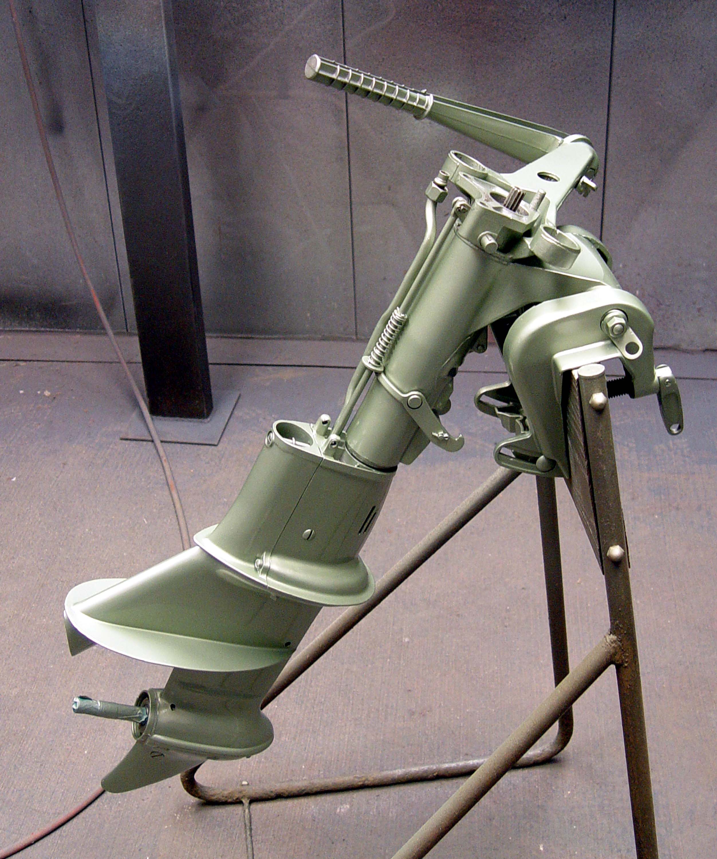
There appear to be 3
different midsections/gearboxes fitted to these motors over the years.
From it's inception in 1949 to probably 1955 was the first as seen below.
Here the shifting rod is accessed directly under the powerhead and
accessible by removing a upper rear cover.
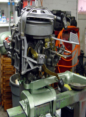
| Here is a stripped down QD-12, with totally different midsection | Here QD-12 powerhead is shown |
 |
 |
The gear box was changed in 1958 from the larger 5 bolt lower unit to a smaller 4 bolt unit. Also there was a internal change in how the pinion gear (drive gear in the gearbox) was attached to the driveshaft with it being changed from a friction fit onto the driveshaft to a splined fit. It appears that all the other gears, shaft and bearings remained the same. This change came about 1959/60, as 1960 parts list shows 2 different part numbers for the pinion gear.
For the1958 and later, if the rear seal (prop shaft seal) is leaking you will need to
replace it, factory #303345, the NAPPA / Sierra part number 18-2022 has
the same shaft .554" dia. but smaller OD (1.00") and wider .375".
While you are there you might as well replace the rear bronze bearing
housing O-Ring also (1.062 ID X .125 thick). NAPPA / Sierra #
18-7117. The whole NAPA gear housing seal kit is #18-2682.
For those of you with the 1957 version or earlier, I am not sure if these parts fit
or not, HOWEVER I suspect most of them will.
To install the new prop shaft seal, be sure the hole in the bearing housing
is clean, lay the housing endways (front down), align the new seal,
start it by hand if possible. Then lay a flat piece of steel on
the seal, tap it in with a hammer. This way it can only go in as
far as the housing allows as the flat steel will stop because it is
hitting the housing.
When you reassemble the shaft and shifting slider dog, be sure that the slider yoke is positioned as shown above. Also the bearing housing has a hole that engages a peg in the upper housing that secures it and keeps it from rotating, be sure that is in the right place before you tighten down the cover.
This gear case does not use a regular gasket, but a spaghetti rubber seal is .100" dia. allowing the two metals to mate tightly. This seal is purchased in bulk so you cut off just a bit more than you need. For this model 11" is enough. This seal is the same as used on all the other models that have the split gearbox, it may just be a different length depending on the size of the motor. It may do the job alone, but OMC recommended it's 3M 847 sealant, but it's kind of pricey hard to find at regular stores. Lots of folks use Permatex #2 Ultra Black with good success and it's available at almost any auto store for just a few bucks. The main thing is that you want to keep it watertight. Also when you lay out the rubber seal in the groove, cut off just a little longer than needed as it will spread out in groove when housing is pressed together.
When reassembling these gear cases, you should use some gasket sealant on the spaghetti seal itself, both surfaces of the clamshell gear case as well, especially around the bolt holes as well as the perimeter of any oil seals.
If you can not find outboard gear oil, go to a automotive store and purchase 80-90W non synthetic gear oil. This would be as close to what the factory originally used. I use the same oil in my rototiller gearbox.
The old 10 hp prior to 1958 had the larger 5 bolt lower unit which were the same as the 15's and 18's had in that same era. The front 4 bolts use the same pattern as the later 4 bolt gearboxes, where it is possible to interchange a 5 bolt pattern onto a 4 bolt pattern, just the rear bolt/stud would extend rearward and not be used.
| Here the 5 bolt gearcase is shown, note the stud on the rear, being the 5th bolt. The 4 bolt units do not have this rear stud | |
|
|
If your motor slips out of gear, you either are missing the shifter lock detent bar on the side of the powerhead, your clutch dog and gears are worn out, or the shift linkage is worn out. Or all three.
| Shown here are the shaft & gears from a QD 23 with the teeth missing from the friction fit pinion gear. Here you can see the sliding clutch dog between the forward & reverse gear | Here the drive (forward ) gear clutch dog engagement notch is worn as evidenced by the shiny corner area |
|
|
|
| Here is what a boater does not really want to see, bad saltwater intrusion & completely rusted beyond any use. | Here the gearbox is removed from the motor & the lower 1/2 also removed showing the gears & shaft bearings. Note the 3/16" hole in the shifting yoke. This is where the Allen headed PIVOT screw goes thru. |
|
|
|
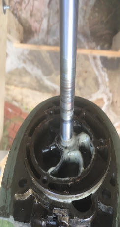
Water Pump Repair : This water pump impeller replace job is a simple after you have removed the lower unit.
Water pumps are basically the same design as still used on all outboard motors. These impellers are a larger diameter than on some of the later unitized lower units, in my book they appear to be able to still function even after many years of usage even after becoming less flexible. The one thing the early units, was that they were made of a pot-metal cast housing that after years of neglect, (especially if used in salt water and not thourohly flushed) the normal deteriorated condition it will be well worn or corroded inside (as shown below). It is then recommended to replace the pump unit with the newer nylon housing with a stainless steel liner version (that is still available) if you have plans on using it in salt water and keeping this motor in your stable for some time.
| QD-12 water pump, top view | QD-12 water pump, bottom view | QD impeller installed in an later pot metal upper housing before final assembly |
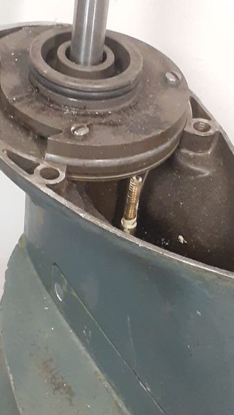 |
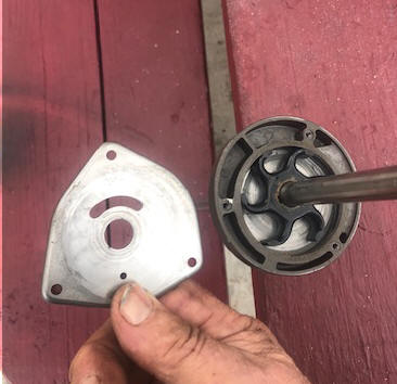 |
 |
| Here is the early pre 1955 water pump without the cover | Here the mid version this one being a 1957 -- 5 bolt version | And the later 1959 version -- 4 bolt version |
 |
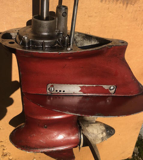 |
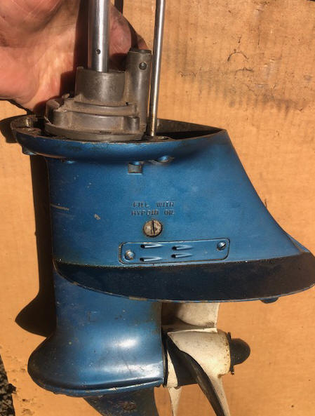 |
What I have found is the early (1949-1955?) have a 1/2' shaft with 11 splines top and bottom. The impeller would be Sierra 18-3002 which was 2 3/4" in diameter, 1/2" thick, with a 9/16" shaft hole and has 6 vanes. The overall length of the driveshaft was 25 3/8". The 3 screws holding the top metal cover are located so that this plate will only fit in one location.
The next version still used a 1/2' shaft, but used a totally different water pump housing, while still using the Sierra 18-3002 impeller. This shaft again has the 11 splines on top and bottom with a overall length of
A change was made in 1958 with a different lower unit which also included the water pump and impeller, which coincided with when the upper cowling was also changed. These used what was known as the 4 bolt lower unit. The pre1958 impeller is the same as the 10, 15 and 18 hp of the same years and used that water pump and the Sierra 18-3002 impeller and has a 1/2" diameter shaft. The 1958 and newer, are the same as the 9.5 hp series which followed this model. The impeller used on these later motors is 2 3/4" in diameter, 1/2" thick, with a 9/16" shaft hole and has 6 vanes. Sierra #18-3003 is the number.
In the LH photo below, note the nylon
O-Ring at the top of this pump housing. This slides into the motor's
mid-section and ensures shaft alignment..
The
black color water pump housing is just a painted pot metal unit as seen at the
upper O-Ring section. I have not been able to readily find the newer type
nylon housing for this model as used on most of the later motors so I am not
sure that they even exist now.
The 1957
that I worked on apparently never saw
salt water, as no corroded bolts anywhere AND the water pump housing was
in excellent shape, compared to other pitted ones I have seen.
Any person familiar with normal outboard repairs should be able to replace one of these impellers in 20 minutes. The most time involved will be re-alignment of the driveshaft and shifting rod. The Clymer flat rate manual says it should take 1.3 hours. However I have found that if you remove the starter unit, then stand the motor upside down on a stool, it is a lot easier for one person to do all three alignments Driveshaft, Water Tub, and Shifting Rod.
| A water pump housing assembly for a long shaft that has had a new style Nylon pump kit installed on a 4 bolt lower unit. | Impeller |
|
|
|
It is recommended you replace the water pump to outlet tube grommet as well. This grommet is held in place by 2 "ears" on the sides that snap into matching holes in the top of the water pump outlet tube.
Many times the grommet has been known to not slide over the tube properly, therefore giving a chance to allow the outlet water from the water pump to leak somewhat. So it is beneficial to lightly grease the lower end of the tube to help it slide in better.
| Shown below is the water pump grommet, note the "ears" |
|
|
|
|
Water Intake : These motors main water supply to the water pump comes from a screened tube right behind the prop in the exhaust outlet. Water is forced into the screened intake to the water pump by the prop thrust. Some users report that when running these motors in a barrel, (usually a small one) that the prop has to be installed and usually in gear as apparently they need to get more water pushed to the water pump by the prop to get enough to cool when running at over an idle.
There is a also a stainless steel intake plate with a few holes near the water pump area on the left side above the cavitation plate shown in the photos below. Flush kits for this motor are rather scarce. There is really no provision currently available for a easy muff system to run this motor out of a tank. But there is hope.
Aftermarket Water Flushing Adapter Cover :
These
motors main water supply to the water pump comes from a screened tube right
behind the prop in the exhaust outlet which utilizes the thrust from the
prop to push water up to the water pump. This method of water intake
does not allow the newer type of flushing muffs to be used. At Soon
after these motors came out with this type a water intake system, Tempo made
Flush Kits #918FAA (as seen in the photos below) for a while for these
motors, but now are not currently made and are rather scarce IF THE PERSON
EVEN RECOGNIZES WHAT THE ARE. Those of you who frequent garage
sales may be on the lookout for these.
|
Evinrude 6hp with Tempo Flush Kit in place |
|
|
This unit is 3" long not counting the hose nut, and is lined with what
appears to be 1/8" sticky backed foam, which provides some sealing and is
held in place on the motor by a mini bungee cord.
|
Tempo #918FAA front view |
Tempo #918FAA rear view |
|
|
|
But There is Hope : These motors main water supply to the water pump comes from a screened tube right behind the prop in the exhaust outlet which utilizes the thrust from the prop to push water up to the water pump. This method of water intake does not allow the newer type of flushing muffs to be used. Flush kits were made for a while for this motor but now are not currently made and are rather scarce. But there is hope.
On the LH (port side) of the exhaust housing just above the anti-cavitation plate there thin stainless steel plate (the factory nomenclature is water bypass cover) which is held in by 2 screws. In this plate are 4 small clamshell type scoops that is designed to put water into the water pump when the motor is in reverse, as shown in the photo on the left below. This is common to many different size of these motors up to 10hp in these years up to about 1974. It was designed to supply water to the water pump when the motor was in reverse, however some motor owners think it is there for added water intake during forward running so you may see them in stalled either way.
I have since talked to a old
time marine mechanic about the direction of those holes. Either he did
not understand what I was saying or since his son took over the business and
he has been out for a number of years, he forgot or did not pay any
attention at the time. After looking at as many as I can come onto, I
now have concluded that the scoops probably were originally installed
forward. A few of these have this plates were painted over originally
and little evidence that it had ever been off, as seen in the LH photo
below. Plus if you look at a factory exposed drawing, these arrear to
be on the forward end.
AND thinking about it, this would supplement a
partially plugged intake screen behind the prop, which seems common with
these motors.
The thought
of them facing rearward IF they are indeed a reverse intake, sounds
plausible, however when in reverse, you would at minimal speed and
will not be doing this for a extended period of time, so possibly
either way would suffice. And most of these old motors I have
seen, which appear that this cover plate have never been molested.
The right
photo below is from a 10hp is an commercial aftermarket adapter (no
longer available) with a 3/8" course thread
placed inward in the rearward part. This allows the usage of Mercury's
Quick-Silver Flushing Device described below. This flush
plate apparently was NOT designed to be used when running, only for flushing,
however this motor was a running motor, with no evidence of failure.
Since these are no longer made, you can fashion one by using the
original plate as a sample and soldering/brazing, (even epoxy) a 3/8" course nut onto
the outside of it to screw the flushing adapter into. Or if your
intention is to leave it in place and run the motor that way, I
would solder the nut on the inside to give less resistance and less
chance of debris hanging up on anything exposed.
| Evinrude with original reverse water inlet plate | Johnson with an old aftermarket flush plate |
|
|
|
In the LH photo below, Mercury sells a flushing adapter that uses a 3/8" National Course bolt thread on one end and a female garden hose end on the other. Mercury's Quick-Silver part number is #24789A 1 with the actual name being Flushing Device. Also OMC Johnson/Evinrude uses the same adapter to back-flush their 9.9/15hp 2 stroke outboard motors (and maybe more models) made from 1993 to 2007. These adapters also fit about all of the Japanese outboards that use a back-flush system.
You can remove the 3/8" plug bolt, screw the garden hose into the adapter, then into the motor, then turn on the water. It does not need to be full force of the standard house water pressure, but about 1/2 force. Start the motor up and let it run for long enough to get the motor warm enough to open the thermostat allowing water to flush thru the power-head.
In the RH photo below, you see a readers removable unit made from scrap metal and a trip to Home Depot.
| Mercury Outboard Flush Device #24789A 1 | Here you see a readers removable version |
|
|
|
The lower unit gearbox is not the unitized type as used on the later 9.9s but has a bottom section that when the unit is turned upside down, exposes all the gears and output shaft. There is a spaghetti type O-Ring that seals the grease in the lower unit when assembled.
OR you can use the garden hose muffs and try to cover the reverse water intake scoops, then with a folded grease rag cover the water intake behind the prop. Then wrap a small garbage bag liner around the rear of the housing including the grease rag and tighten a ratchet strap around holding the grease rag tight. Kind of a redneck approach, but in a pinch does work.
Prop : In the early/mid 1970s OMC offered a accessory Lexan prop for the 9.5 hp. That is all they offered for a short time was the replacement 3-blade, 8 1/8 diameter, 8" pitch prop (part # 385940) but later they dropped them and reverted back to the aluminum props. That same prop was also spec'd as the replacement prop for 1958 - 63 10 hp motors.
The prop is secured by the old style, using a cotter pin thru a threaded plastic nose cone, using a 9/16" X 16 thread. It is a 3 blade aluminum secured to the prop shaft by a 3/16" dia. by 1 5/16" long shear pin. The prop has a 9/16" hub hole.
| Prop & nose cone with cotter pin inserted. | Lower unit showing drain & fill plugs |
|
|
|
The 1960 Johnson motor that I worked on had a distance between the transom clamp area (where the top of the boat transom would be) to the cavitation plate of 18". The owner thought it was a "Long Shaft", but upon measuring from the clamping area which would be the transom to the center of the prop it was 22", the same as most all later short-shaft motors. The difference was really that the prop was a smaller diameter with the cavitation plate closer to the prop. I also suspect that this was common before the later motors labeled "Short Shaft" became standard at 15" to the cavitation plate.
Black
or Gray Oil Coming Out of the Lower Unit Holes :
Many of these motors
(especially these older motors that have to use a richer fuel/oil mix) are basically used as a secondary motor, and usually then
as a trolling motor, which are ran for considerable length of time at a lower RPM.
The fuel oil mixture ratio of 24-1 or even 32-1 is probably too rich for this type of usage. The black oil that seeps
out of the motor is just unburned oil from the gas mixture. The black
color is coming from the carbon created during the pistons firing situation
and is accumulated unburned inside the exhaust housing. When the motor
sets for a while the excess unburned oil
in the fuel is mixing with and softening up the carbon, creating the black oozing
oil. You can reduce the amount somewhat by properly adjusting the
carburetor idle jet to it's leanest position, also where the motor runs best at an idle.
This black or gray oozing oil could be also because of a stuck open thermostat which would not allow the
motor to warm up. However thermostats that get stuck usually do it in the
closed position, so a bad thermostat is usually not the cause of this condition.
Or, it could be a 6 gallon tank that the fuel line is still attached to the motor during storage while the outside ambient temperature is high enough to expand the fuel inside the tank to where the gas is forced into the carburetor and IF the needle valve is leaking, it will force fuel into the engine and out the exhaust which mixes with the exhaust carbon, then leaches out as BLACK oil out the prop's exhaust.
If you are getting a thick creamy gray oil oozing out the
drain hole on lower unit, it is
essentially the same as above except the inside of the housing may have less
carbon build up, therefore the color will be lighter. It is the same thing as
described above, but possibly from a new or rebuilt motor that may not have been run much for some time
and there is not a lot of carbon inside the exhaust housing.
If there is minimal carbon built up from previous
runnings, the oil will
be the thick creamy light gray color that has a lot of water mixed in it. This
could also be caused by the converging ring (#332395) is missing on the prop.
This plastic ring facilitates a suction from the outside of the prop when the
motor is running at a slow speed to help suck more of the exhaust gasses away
from the "thru the prop exhaust" when idling in neutral or running slow.
| Here a creamy colored oil is exiting the motor's exhaust housing. This is basically the same concept as the black oil except probably in a cleaner motor |
 |
This oil
seepage may not be evident until a day or even a week after usage, then will
seep out up to a couple of months later. Most repair shops just recommend
that for most boaters to then simply
live with the idea that you may have to wipe it down after each usage.
You could also see this oil seeping out of the front lower unit water drain hole. It is observed that if these motors are used on a smaller boat as the only propulsion, and act as a "get there" motor and also as a trolling motor, this black residue is considerably less to almost non-existent because the motor gets hotter because of the faster RPM, where the motor has a chance to warm up, thereby "burning" some of this excess oil.
Copyright © 2009 - 2023 LeeRoy Wisner All Rights
Reserve
Back to the Ramblings
Home Page
Originated 8-02-09, Last updated 12-06-2023
Contact the author