|
Maintaining Johnson
1992 - 2005, 2 cycle |
 |
Johnson, Evinrude, OMC, outboard motor, outboard
motor repair, 9.9, 15 hp, date/year of manufacture, water pump, carburetor, long
shaft, 15 hp conversion, sailmaster
In the above header photos, the one on the left is a 1992,
while the one on the right is a 2003.
One thing that I want to convey here is that I write only on motors that I have
actually worked on, and over a period of MANY years, consisting of many THOUSANDS
of hours, and then more in maintaining/updating these articles. They are
motor specific, HOWEVER if you are having a diagnosis issue, my Trouble Shooting
article covers MANY more aspects that may help you diagnose your issue.
CLICK
HERE for access to that
article.
I did not own this motor but did have the use of this 1992 motor to use and examine it while repairing mine, so the following are my observations. It trolled all day long (7 hours) at a faster salmon trolling speed on 3 gallons of fuel. This motor would be a good choice for a lake trolling motor, but for even a 16' boat trolling for a bay type fishery where the current and or wind is prevalent, it just does not have the thrust to contend with the wind unless you speed it up considerably to counteract and keep it on course.
In the upper banner the picture on the left is 1992 to 1997. The motor I will be describing was made in 1992. These motors have a new designed recoil starter that bolts onto the upper part of the motor similar to the post 92 9.9/15hp motors. This one has on the nameplate made in Belgium, and another motor I observed did also, however they both were sold in the US. The connection to Belgium is not known, unless this was the first of the new design and was made there before the US could gear up for it on that model. Upon later tracking things down, it appears that this series of motors were made in either Belgium or Hong Kong.
The water indicator hole tube comes off the powerhead's left side upper water jacket. There is no "Flush Plug" on the block to flush the motor thru. The thermostat is on top of the head like the 86 and later 9.9s.
The lower cowlings are made of plastic and similar to the 93 and newer motors, also it uses the same basic upper cowling rear latch as the 93 9.9. There are no side cowling bumpers to protect the motor, but has rubber leveling pads on the rear of the lower cowling for support if the motor is laid on it's rear.
Year of Manufacture : This is important in any repair, for obvious reasons. Prior to 1979, Johnson used the last 2 digits of the year in the model number. Here is a LINK to help you determine any of the Johnsons. And here is the LINK for the Evinrudes. For those of you readers outside of the United States, here is another LINK that may better help with your motors.
After 1979, OMC's manufacturing year code, which included Evinrude, is the word "INTRODUCES", with each letter equating to a number ie: I=1, N=2, T=3, R=4, etc. as illustrated below. As before, the last 3 letters are what you are looking for. Then in this case, disregard the last one, as it pertains only to a model revision that only on specific cases may be revalent to a marine repairman if problems arise. A code of J10ELENA would equate to Johnson, 10hp, Electric start, Long 20" shaft, EN = 1992, & the A could be a model revision, so this motor would probably be made in the very first part of the year. You may encounter a code of something similar to J10SELCTC. This would have been Johnson, 10hp, SailMaster, Electric start, Extra Long shaft, 1983, and the C could be a model revision. In this case with the SE in the model number, indicating a SailMaster, all the SailMasters would have all had the extra long 25" shaft. For more detailed information on worldwide production, CLICK HERE
|
CODE |
I |
N |
T |
R |
O |
D |
U |
C |
E |
S |
|
|
1 |
2 |
3 |
4 |
5 |
6 |
7 |
8 |
9 |
0 |
Using this code system, if the motor was sold as an Evinrude, then the first letter would have been an E instead of the J. Then you can encounter motors made in or for other countries, which will have some added letters as mentioned later in this article.
There should be the model and serial number on riveted on 1” X 2” aluminum ID plate on the LH side of the transom mount bracket (looking forward). Sometimes this ID plate can get removed. If this happens, you can still usually tell which motor it is by looking at the 25 cent size soft plug in the upper rear RH side of the block. The model and year are stamped in this soft plug also but probably only up to 1979. It is interesting to also note that the 6 hp uses the same block as the 8hp, so you could see either hp with the same 6R78M numbers here as the 8hp has. You may find that the plug numbers do not match any of the codes, as the factory changed things as time went on.
Exploded Parts Lists : For a internet link to a marine parts seller CLICK HERE that has exploded views as shown below in this article. From this business, you can identify the numbered parts and purchase parts online from them.
| Front view | Rear view |
|
|
|
The twist grip throttle and kill button are very similar to the 9.9 with the exception that the kill button is mounted in the handle about mid section but does not angle like the pre 93 9.9s, but is set at 90 degrees to the handle. It also has a friction lock on the throttle similar to the Sail-Master 9.9s. The choke lever is in the same basic location, but is shaped different. There is a carrying handle mounted between the clamp screws that pivots forward.
Internal Engine Parts : One major internal difference was this engine now uses caged needle bearings for both the center main crankshaft bearing and the connecting rod bearings. A GREAT IMPROVENT for the shade tree mechanic.
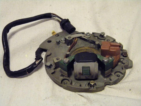
Electronics : The electronics uses the Capacitor Discharge type with a powerpack up until about 1990, after that it was changed to the Under The Flywheel type.
| Under Flywheel electronic ignition system |
 |
| Timing plate assembly |
 |
Manual Starter : You will notice the newer type manual starter and flywheel similar to the 1993 and newer 9.9 motors. The throttle linkage again is very similar also. There appears to be no provision for an electric starter.
| Left side | Right side |
|
|
|
Carburetor : The carburetors appear to be virtually identical for both the 6 and 8hp, with only a possible larger main jet for the 8hp and larger throat. These carburetors from 86 on had plastic top covers, also plastic bottom fuel/float bowls. About mid 1987 the idle jet was moved from the front center of the top cover, to the rear RH side (facing forward). The old front idle jet hole was plugged with a screw of the same size as the old jet threads and a gasket under the screw head. This new idle jet is smaller in diameter, is angled from the upper outside down into about the center of the plastic top. This late version, to adjust the idle, you have to remove the motor's cowling.
It appears that this new style top cover could be used for either idle jets depending on the version or placement of the breather.
The top cover is threaded at the rear on the top LH side for the throttle arm pivot point screw. Shown below the 2 top holes that are empty are used to hold the air breather on in addition to adding extra top cover screws.
| Carburetor off a late 87 and newer |
|
|
Fuel Pump :
These fuel pumps are
pretty universal, the same small square one fitting most all these small motors
up to 40 hp until about 1987 depending on the size or version of motor.
This model appears to NOT have moved up to the
newer larger style fuel pump #0438559
(which they tried but only on the 1987) that used on the larger motors of the same time frame.
So possibly these 6hp and 8hp motors were the break off point and stayed with
the smaller fuel pump, as the 9.9hp used this newer larger fuel pump on it's
electric start motors of this era, but stayed with the smaller pump for it's
rope start versions. For a link to the
rebuild procedure for this small square fuel pump,
CLICK HERE.
Fuel Filter : This series of motor utilized a filter screen on the intake of the fuel pump, as seen in the photo below under the black plastic inlet is secured by a single center screw. By removing this screw, this fuel inlet cover can be removed, UNDER and pressed into the underside is a fine stainless steel filter screen. Also is a Neoprene gasket just the shape of this cover. The cover and gasket have 4 scallops corresponding to the 4 fuel pump bolts. If this fuel inlet needs to be rotated for better fuel line alignment, it can be rotated 4 different 90 degree locations.
| Here is the fuel pump showing the removable inlet cap/screen |
|
|
These motors use the
single fuel line and the standard OMC quick couplers.
Recommended Fuel / Oil Mix : The formula shown below will be on all modern 2 cycle oil sold in the last 30 years or so. On most all of the pints and quart plastic bottles of TWC-3 oils there will be a narrow clear vertical window on the edge of the bottles. On the sides of this window will have numbers representing ounces and Milliliters for other parts of the world. Or you can purchase special measuring containers showing different ratios and the amount of ounces needed.
If your motor is to where you have to mix the oil, you need to know how much gasoline you will be needing, add the oil before you fill the fuel tank so that the oil mixes better that just dumping it in after you fuel up. However if that is not possible, guess, add a majority of what you think it will take, fuel up and then add the rest matching the amount of gasoline you took on. If you are using portable fuel thanks, before hand, when you fill it, add 1 gallon at a time, use a clean 3/8" or 1/2" dowel, mark the dowel at each gallon and use it as a measuring stick. This way you can refill a partly full tank with the known amount of oil.
A quart has 32 ounces of oil in it. So for a portable 6 gallon tank to fill it using the 50:1 ratio would take 16 ounces, (1 pint) or 1/2 of the quart.
|
FUEL MIXING TABLE |
|||||
| Gallons of Gasoline |
Gasoline to Oil Ratio |
||||
|
Ounces of Oil to be Added |
|||||
| 16:1 | 24:1 | 32:1 | 50:1 | 100:1 | |
| 1 | 8 | 5 | 4 | 3 | 2 |
| 2 | 16 | 11 | 8 | 5 | 3 |
| 3 | 24 | 16 | 12 | 8 | 4 |
| 4 | 32 | 21 | 16 | 11 | 6 |
| 5 | 40 | 27 | 20 | 13 | 7 |
| 6 | 48 | 32 | 24 | 16 | 8 |
The official OMC fuel/oil mix for most outboard motors in this year ranges has for years been 50:1. This means 50 parts of regular gasoline to 1 part of outboard motor oil. Remember that this was before unleaded gasoline or even possibly an octane rating that was listed at the pumps. Now the recommended fuel is 87 octane gasoline. Or before the outboard industry came up with any TWC oil, much less the latest which is TWC-3 outboard motor oil. You probably will not see much of the older TWC-2 oil out there anymore. You can spend your money and purchase OMC oil for about $6.50 a quart, or buy a name brand quart for $2.79. Sure the manufacturers want you to buy their oil, and for a new motor under warranty, it may be advisable to do so. But the consensus from many experienced boaters is to use any good brand of oil, as long as it has the TWC-3 rating, it meets or exceeds the manufacturers specifications. The TWC-3 represents, Two cycle, Water Cooled, type 3 formula. The formula 3 has decarbonizing additives designed to be more compatible with the newer non-leaded fuel.
So from the above information, you can see that fuel and oils have changed dramatically since these motors were first brought out in 1974. In this instance, times have changed for the good, as we now have a better gasoline and way better outboard oils.
Fuel/oil mix on all the OMC motors that have needle roller bearings is 50-1 of TCW-3 standard outboard oil. However I have found that since I troll much of the time, other than getting there and back, I like to use a mix of 75-1 but of a SYNTHETIC blend oil instead of the standard oil. This gives me at least the same or better motor lubrication, plus it gives me less smoke at a troll & the spark plugs last longer before fouling.
Midsection / Shifting :
This 92 motor uses the newer type front
mounted shifting lever and most other associated parts as the 93 and later 9.9
motors. The lifting / carrying lever is similar to the 93 9.9s. The tilting
lock lever rotates as with the previous model.
| Exploded view of Midsection |
 |
One thing was experienced is that the shifting lever HAS to be in neutral, otherwise if the starter rope is pulled, it may stick in the pulled position. It usually can be convinced to retract by moving the shifting lever to neutral, or into reverse and then back to neutral again.
Water Pump : The water pump is essentially the same as most small OMC motors of this era. The disassembly of the lower unit to replace the impeller is that the shifting rod rotates as with the previous model instead of moving up & down. It is connected by a spline on the upper shifting rod end to the shifter lever unit under the carburetor.
Overheat Problems at Troll or in Tank : If you happen to have the motor overheating at slow speeds, you might consider looking at the water intake screen tube which is situated in the lower unit directly behind the prop. This is placed here so that the prop thrust pushes fresh water into this slotted screen tube. If the factory or more likely a subsequent owner may have repainted this area & inadvertently blocked enough of these holes to partially block water intake at a slow speed.
This slotted screen would be hard to remove and save after many years, and expensive to replace. So using a small nail or similar tool, you should be able to carefully clean any debris from the holes clear enough to make a difference.
Water Intake :
These motors main
water supply to the water pump comes from a screened tube right behind
the prop in the exhaust outlet which was carried over from earlier
motors. Water is forced into the
screened intake to the water pump by the prop thrust. Some users
report that when running these motors in a barrel, (usually a small
one) that the prop has to be installed and usually in gear as apparently
they need to get more water pushed to the water pump by the prop to
get enough to cool when running at over an idle.
There is no stainless steel intake plate on the left side above the cavitation plate like the previous versions. Aftermarket flush kits for this motor are obsolete and rather scarce. There is really no provision currently available for a easy muff system to run this motor out of a tank. But there is hope. I think that I may be able, (by tearing mine down) to figure out a way to drill/tap/modify the lower unit near the water pump to where I may be able to utilize the later screw in flush adapters on this motor. But that is a project in itself.
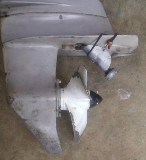
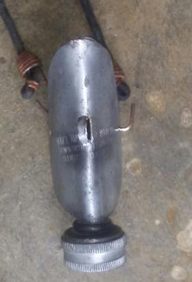
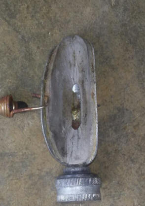
Aftermarket Water Flushing Adapter Cover : These motors main water supply to the water pump comes from a screened tube right behind the prop in the exhaust outlet which utilizes the thrust from the prop to push water up to the water pump. This method of water intake does not allow the newer type of flushing muffs to be used. At Soon after these motors came out with this type a water intake system, Tempo made Flush Kits #918FAA (as seen in the photos below) for a while for these motors, but now are not currently made and are rather scarce IF THE PERSON EVEN RECOGNIZES WHAT THE ARE. Those of you who frequent garage sales may be on the lookout for these.
| Evinrude 6hp with Tempo Flush Kit in place |
 |
This unit is 3"
long not counting the hose nut, and lined with what appears to be
1/8" sticky backed foam, which provides some sealing and is held in
place on the motor by a mini bungee cord.
| Tempo #918FAA front view | Tempo #918FAA rear view |
 |
 |
Lower Unit : The lower unit is a unitized design smaller than the 9.9 but does not use the thru the hub exhaust. The water intake is in the exhaust tube right behind the prop as used in the older smaller OMC engines as seen by the screen hanging down in the photo below. And it offers no real opportunity to attach a flushing attachment. The prop has a shear pin and the plastic bullet nose is just a retainer that is held in place by the cotter-pin.
| Exploded view of the lower unit | |
|
|
This lower unit is a simpler unitized unit than the 9.9 but for water pump repairs very similar to about all of the OMC motors of this vintage, except there is no shifting rod link coupler or retainer screw. This motor does not use a vertical movement shifting rod, but a rotating one. The shifting rod comes off when you take off the lower unit and stays in the lower unit. It has a flat on the upper end of the round rod that engages into a slot in the pivoting shifting linkage inside the housing just below the powerhead.
To remove the lower unit, just remove the 3 or 4 bolts that hold the lower unit on and pull the unit down and off. When you reinstall the lower unit, the upper end of the shifting rod really aligns quite easily into its receptacle and is held there when you re-bolt the lower unit back on.
| Lower unit & prop | Nameplate |
|
|
|
For flushing or running this motor out of the water, you will need to put it in a barrel as the company that made flushettes for motors like yours called it quits a few years ago (Tempo Products).
Propeller
:
The prop has a shear pin and the plastic
bullet nose is just a retainer that is held in place by the cotter-pin.
OMC / Bombardier #390237 — propeller, (Part replaced by OMC 0778797)
8-1/2" X 9" 3 blade, (5/6/8hp models) EXCEPT long shaft models which use a different one.
Or Michigan Wheel propeller, 1980 & newer
Johnson 6 / 8hp #012032 8 1/2" X 9, 3 blade $81.99
As for repairs, it seems to be a very simple proven design that by my limited exposure to it the only thing I see a detriment is that you need a special flush unit as the regular muffs will not function.
Copyright © 2007 - 2021 LeeRoy Wisner All Rights Reserved
Back to
the Main Ramblings Page
Originally stated
09-16-2007, Last Updated 12-28-2021