Maintaining Johnson/Evinrude
5.5 hp CD/Fisherman Series
2 cycle Outboards

1954 - 1964,    1956 – 1964   (General Repairs  

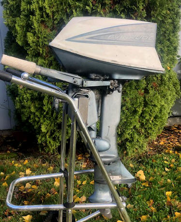
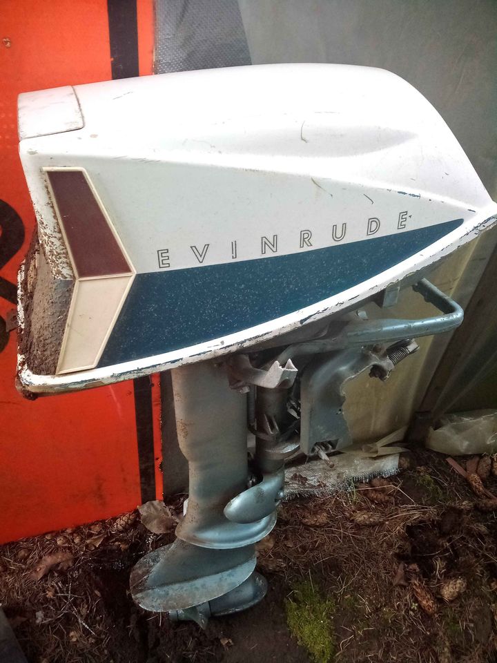
                        1962                                                                                                                                                                                            1954


One thing that I want to convey here is that I write only on motors that I have actually worked on, and over a period of MANY years, consisting of many THOUSANDS of hours, and then more in maintaining/updating these articles.  They are motor specific, HOWEVER if you are having a diagnosis issue, my Trouble Shooting article covers MANY more aspects that may help you diagnose your issue.  CLICK HERE for access to that article.


   This size and series of motors was spanned about 10 years, apparently they had a mindset on 5HP motors, and did not want to loose customer support, so stayed below 6hp  (??).  This series of motors, both Evinrude and Johnson went through a lot of cosmetic or minor changes to the motor, especially the shroud.  Also the carburetor breather was changed later in it's production life.  These changes were possibly because Evinrude bought out Johnson and formed OMC (Outboard Marine Corp) in 1956, so the early few years of their models were different until the two companies got their engineering together.

    It also transitioned from the old pressurized tank Siamese fuel line to the new fuel pump and single line in 1960.


    The top cowling was changed on both the Evinrude and Johnson from aluminum shrouds to fiberglass in 1959.  These were totally different as to the Evinrude and Johnson, not just the paint job.


    It morphed into, and was replaced by the 6 hp Evinrude Fisherman or Johnson CD series in 1965.  However Evinrude used the name "Fisherman" for BOTH this 5.5 hp AND the 6hp.  Therefore just about everything that I have already written for the 6 hp model will pertain to this 5.5 hp one (except the fuel system, starter and shifting rod).   CLICK HERE  for that link.  Another change was this being the earlier model, the shifting linkage was different on the 6 hp, (explained later in this article)


   Here there are basically two versions, (1955 -1962) which was basically the little brother of the 10 hp QD CLICK

HERE,  and the later (1963 - 1965) being a parent of the 6 hp CD.  Except both used the older top mounted QD recoil starter shown below, where the 6hp sported a new spindle Bendix type starter spool.


Year of Manufacture :  This is important in any repair, for obvious reasons.   For Johnson, the 1954-1964 were designated CD models.  Evinrudes model code uses the first number as the HP, second year and third/forth the version, where usually, say as illustrated below 5502 being a 5hp, 1955 year,  being a short shaft, where the 5503 would be a long shaft.  They were made in standard 15" shafts or the long 20" versions where Johnson designated by a 3rd letter L in the model number.   However finding a longshaft motor of this series is quite rare as in those days most of these small motors were used on small fishing boats and not as axillary kicker motors for larger fishing boats. 


     At times this code does not follow through as you would think in the ideal world, as it appears they had so many slightly different models that no one had a crystal ball and foresaw into the future .

    This chart listed below appears to have a few gaps in it, probably because of lack of good recorded data prior to 1956.

          Johnson                                       Evinrude

     CD / CDL 10 /11                         5502 / 5503   = 1954
    CD / CDL 12                                5502 / 5503   = 1955
    CD / CDL 13                                5512 / 5513   = 1956
    CD / CDL 14                                5514 / 5515   = 1957

    CD / CDL 15                                5516 / 5517   = 1958

    CD / CDL 16                                5518 / 5519   = 1959

    CD / CDL 17                                5520 / 5521   = 1960

    CD / CDL 18                                5522 / 5523   = 1961

    CD /CDL  19                                5524 / 5525   = 1962

    CD / CDL 20                                5302 / 5303   = 1963

    CD / CDL 21                                5402 / 5403   = 1964


  Statistics For These Motors :


These motors develop  5.5 hp @ 4000 RPM

Cylinders               2
Bore diameter      1.940" 
Stroke                   1.500"
Displacement        8.84 CI
Starter                  automatic rewind
Bearings,              bronze bushings for all mains and the rods

Carburetor -         Johnson  Tillotson type, throat dia. .612" - Carb kit Sierra 18-7043
High speed jet,     adjustable up until 1963,  Starting point 1/2 turn out
Idle jet -               1 1/4 turns out as a starting point
Fuel capacity  -   Remote tank pressurized Siamese hose from inception until 1959, fuel pump single hose after that
Fuel mix -            Oil 1/3 pt. (22-1)  SAE-40 per Gal for pre 1962 motors, 50-1 for later motors
Point gap      -      .020"
Plug gap -             .035", Champion J4J or J6C spark plug.
Flywheel key -     Woodruff .154" (5/32") wide x .235" thick x .603" long
Flywheel nut  -    7/16" NF, -- 3/4" wrench size
Water Cooled -    rubber vaned impeller type - Sierra #18-3001
Gearbox oil -       90 W gear oil
Gear Ratio -        15-26

Prop.                    RH  - 2 Blade  8" x 7 1/4"   or   3 Blade  8" x 5 1/2" for late motors 

Prop Drive Pin -   .187" X .862" OAL

Prop nut retainer pin  -       None
Prop nut  -           None,  Rubber nose cap

Weight 56#

     A couple of years ago, I picked up a 1962  5.5hp Evinrude from a Face-Book Messenger add.  I paid $40 for it.  The owner had little information, only that he had it given to him by  his brother, but his preliminary trying to get it running proved fruitless, so he abandoned the idea of fixing it and bought a newer running motor.    After I got into looking deeply at it, I am sure that he knew way more than he was telling me.


   On the plus side, the starter rope pulls the motor over.   I did get the clamp screws somewhat functioning using WD-40.  And I did manage to un-seize the tilt unit.  The swivel steering system is a whole another challenge.   It is pretty obvious that this motor had been exposed to salt water numerous times in it's past, and then has sat outside in the elements for a considerable length of time after that, as MANY of the non-stainless steel screws were so rusted that the only way to get them out was to cut the heads off.  One ear of the base that holds the tiller handle was broken off.  This project looks like another challenge, as replacement rings are not available, but head-gaskets and water pump impellers still are. ??


   In the LH  photo below you will notice that the lower unit fill/drain plugs are missing and the tiller handle not attached (base broken) , but it has the newer designed motor cowling.


Here is my 1962 acquisition Here is my "NEW" 1964 acquisition


   Fuel Pump :  The first 8 years of production of this model (up to1961), used a different fuel pump as this motor used the dual Siamese pressurized fuel tank.  Here the intake manifold was designed (using the 2 cycle) principle of alternating pressure/vacuum inside the crankcase to pressurize the fuel tank with one line and forcing the fuel back with the other line.


      As seen in the LH photo below, The large rubber tube is simply the seal for the upper cowling.  The small black rubber tube comes off the intake manifold, and the clear vinyl tube is the fuel line into the settling bowl on the bottom of the carbureator.  

Here you see the early style fuel pump utilizing the intake manifold Here is the first style actual fuel pump, slightly different than the ones used on later motors 


Fuel Tank & Lines :  These motors transitioned from the older (dual) Siamese fuel lines where the fuel pump was incorporated in the carb intake manifold.   These tanks had a built in pump knob to initially pressurize the tank, then the motors pressure out the line from the manifold took over from there.  Later 1962  which use the new style vacuum tank and the single fuel line and fuel pump commonly found nowadays.  


   Fuel Filter :  This series of motor utilized 2 different fuel pumps, depending on the year of production.   Both utilized a filter screen on the intake of the fuel pump. The early model fuel pump, under the center screw surrounded by a rubber ring, which secured the screen cover allowed the owner to access this screen as seen in the LH photo below.  When the factory went to the new style fuel pump on this model in 1967, this pump also included a fuel filter screen, as seen in the RH photo below the black plastic inlet is secured by a single center screw.  By removing this screw, this fuel inlet cover can be removed, UNDER and pressed into the underside is a fine stainless steel filter screen.  Also is a Neoprene gasket just the shape of this cover.  The cover and gasket have 4 scallops corresponding to the 4 fuel pump bolts.  If this fuel inlet needs to be rotated for better fuel line alignment, it can be rotated 4 different 90 degree locations.


    Recommended Fuel / Oil Mix :   On these 2 cycle motors you have to mix the oil with the gasoline to lubricate the internal parts of the motor, so you need to know how much gas you will be needing, add the oil before you fill the fuel tank so that the oil mixes better than just dumping it in after you fuel up.  However if that is not possible, then guess, add a majority of what you think it will take, top off the tank and then add the rest matching the amount of gasoline it took to fill the tank.  If you are using portable fuel thanks, before hand, when you fill it, make you a stick gauge, by adding 1 gallon at a time, use a clean 3/8" or 1/2" dowel start filling the tank, mark the dowel at each gallon you add, then you can use it as a measuring stick.  This way you can refill a partly full tank with the known amount of oil.


    These early motors used bronze bushing type bearings on the connecting rod, requiring a richer fuel/oil mix (22-1) as compared to the later (1962 to 1964) motors that have needle roller bearings (this motor included) is 50-1 of TCW-3 standard outboard oil. 


  The formula shown below will be on all modern 2 cycle oil sold in the last 30 years or so.  On most all of the pints and quart plastic bottles of TWC-3 oils there will be a narrow clear vertical window on the edge of the bottles.  On the sides of this window will have numbers representing ounces and Milliliters for other parts of the world.  Or you can purchase special measuring containers showing different ratios and the amount of ounces needed.


FUEL MIXING TABLE

Gallons of Gasoline

Gasoline to Oil Ratio

Ounces of Oil to be Added

16:1 24:1 32:1 50:1 100:1
1 8 5 4 3 2
2 16 11 8 5 3
3 24 16 12 8 4
4 32 21 16 11 6
5 40 27 20 13 7
6 48 32 24 16 8


     The official OMC fuel/oil mix for most outboard motors in this year ranges has for years been 22:1.  22-1 is a odd ratio, so it is easier to mix 24 -1.  This means 22 parts of regular gasoline to 1 part of outboard motor oil. 


     Remember that this was before unleaded gasoline or even possibly an octane rating that was listed at the pumps.  Now the recommended fuel is 87 octane gasoline.


     Early on for the 2 cycle motors the recommended oil was regular automotive 30 weight motor oil, then the outboard industry came up with any TWC oil, which finally evolved into the latest which is TWC-3 outboard motor oil.  You probably will not see much of the older TWC-2 oil out there anymore.  You can spend your money and purchase OMC oil for about $6.50 a quart, or buy a name brand quart for $3.59.  Sure the manufacturers want you to buy their oil, and for a new motor under warranty, it may be advisable to do so.  But the consensus from many experienced boaters is to use any good brand of oil, as long as it has the TWC-3  rating, it meets or exceeds the manufacturers specifications.  The TWC-3 represents,  Two cycle, Water Cooled, type 3 formula.  The formula 3 has decarbonizing additives designed to be more compatible with the newer non-leaded fuel.


    So from the above information, you can see that fuel and oils have changed dramatically since these motors were first brought out in 1954.  In this instance, times have changed for the good, as we now have a better gasoline along with way better outboard oils.


   DO NOT use oil designed for your weed whacker or chain saws as these air cooled motors run a lot hotter than the water cooled outboards.   The water cooled outboards require the specially designed TWC-3 oils.


   Carburetor :   To remove the carburetor, you will need to disconnect the fuel line, the choke lever and low speed knob (sometimes called the idle jet).  This Rich-Lean knob just pulls off the finely splined shaft straight forward.    Remove the carb cam roller pivot screw and rotate the roller unit off the linkage rod.  Remove both the the carburetor nuts (7/16" wrench), slide the carburetor forward off the mounting studs. 


   The carburetor shown below is the basic simple standard unit but from about 1971 on using the fixed main-jet style.  Earlier motors prior to about 1970 had an adjustable main-jet in place of the #29 plug screw shown in the illustration below.  You will have to loosen and remove the rewind starter spool so you can get to the throttle lever pivot nut so you can then get a wrench on the port side carburetor nut.


Exploded view of carburetor Here is a close-up top view of the 57 carburetor, note the lower adjustable high speed mainjet shaft


    You can usually tear the carburetor apart, soak it in a carburetor cleaner overnight, blow it out with compressed air and reassemble without purchasing a repair kit.  Just spraying carburetor cleaner in it does not constitute cleaning even if stripped down.  You may luck out and not have to remove the pea sized aluminum welch plug on to rear center or the 2 lead shot sealed passageway covers.  If not, then plan B is do it over but remove these plugs and clean everything including the passageways under the se plugs. 


    The float is varnished and may look cruddy, but if it is still intact and seems to float in gasoline it should function.  All that is usually needed is to check to see that the float level is with the bowel flange when assembled without the bottom bowl on and turned upside down.  If not parallel, then bend the metal stop tab on the float needle valve area to adjust the float level.  If the float is not set at the correct level for the shut off point under pressure from the fuel pump in the carburetor, this could cause motor to run lean or rich. 


    Some carburetor repair kits cover a wide range of HP ranging from 5hp even up to 20 hp, however do not think just because the kit is the same for a 20hp as it is for the 6hp that they use the same carburetor.  The kits may have numerous extra parts, as main jets where you just use the one required for your motor.  The breather throat of the carburetor may also be a larger diameter for different hp of motors.


   The main jet orifice in the bottom of the bowl has a recess on these models and be full of crud, even though they look clear.  On the earlier models (pre-70) there is a adjustable main (high speed) needle jet on the front lower bottom, this needs to be removed for cleaning.  On the later carburetors there is a clean out plug in front that you can access this orifice.   Use a proper fitting screwdriver to remove the orifice, but be sure there is no debris in or behind it.  Be sure the plug screw has a good sealing gasket.  This plug is in the same location that the early carburetors had a adjustable main needle jet.


   Inspect the idle needle jet to see if it is bent or has the tip broken off, (on these the tip does not come to a sharp point) straighten if need be or purchase a new one. Reinstall this jet needle / rich-lean screw, check the packing nut for tightness to insure there is no air leak around the shaft.   The correct way to adjust this low speed needle, is to turn it all the way in until it is lightly seated.  You then turn it back out 1  1/2 turns.  That becomes a reference point for further adjustment.   I like to be able to get a equal rotation each way so set the knob at about what would be 4 on the top.  This should give you a basic setting.  Once you get it where you want, you can pull it off, then reposition the knob where you want it.


   With the motor warmed up and the twist throttle in a SLOW position approximating your intended slow/trolling speed, turn this low speed needle jet in about 1/8 of a turn, let the engine run for about 15 seconds to respond to your new setting.  Do it again then wait for the results.  A cough is indicative of a rich mixture. Too lean it will just die.   When you make this change and the engines either sputters or wants to die, back it off to the the last position then this should be close to the ideal setting.   If you go to rich it will cough AND then die.  You can now pull the idle knob forward and off the splined shaft, reposition it so that the knob pointer is down so you will have movement either way from this position for fine tuning if needed.  This low speed setting does not effect the high speed running of the motor.  However it you set it too lean, you may later have a issue with it not wanting to start when it is warm.


   One thing if you look at the top of this carburetor, the 1/8" hole at mid-section topish is not plugged with a lead shot like all the rest.  My thinking was did I loosen it and loose the plug?  Well, after I got it running I covered that hole with my finger and the motor wanted to die.  After numerous tries, I decided it was not supposed to be plugged anyway and probably there as a vent to alleviate any vacuum inside the float bowl.


    In reinstalling the carburetor to the intake manifold, you may have to position it so that it just starts onto the studs, then start threading the nuts on equally before finally tightening them.  What I am saying that there may not be enough room to start the LH nut if you have the RH nut tight.


    If when you get it all back together and can not get it to idle no matter how you adjust the High/Low speed knob and the idle needle is not worn or bent, you might be sucking air around the shaft behind the shaft packing nut.  Tighten the nut down to where you still can rotate the shaft.  If that does not do it, smear some chassis grease around the nut threads and the shaft where it enters the nut.  If that helps, then you need to repack the packing gland area behind the nut.  I have some OLD graphite impregnated water pump packing cord (probably can not buy it anymore) that I unwind a strand of cord and use it for packing under the nut.  Or you now may be only able to get a Teflon string packing.  You could possibly also use some sting type cord that you impregnate with grease.


Commonly Lost Part :  There is also a Z link rod (shown below) This ties the roller bar unit to the throttle valve of the carburetor.  Do not loose it either, or a makeshift one will need to be fashioned from a piece of welding rod.  The important thing here is to get the bends just right so that the timing is consistent  when the timing plate moves this roller forward to give movement in the throttle valve increasing fuel flow.


   In the illustration below is the dimensions for it if you need to fashion one.  These appear to all be the same for these 6 and 8 hp motors from 1965 to 1979, AND the 9.9/ 15 hp from 1974 up until about 1986. (And maybe more) after that, there is a different number that has a slight "V" bend front to back.


OMC # 312830  Link, cam follower


    Breather :  These will usually be called a silencer in the industry.  Here you will find two styles of breathers as seen in the photos below. The early motors do have a dual canister type, while the later ones have no breather box, as the mouth of these carburetors is open behind the front of the cowling.


Here the early dual breather boxes, looking from the rear here is the later carb with not breather


Here the 64 front panel, note the low positioned slow speed knob requiring the linkage as seen on the right Here the 64 carb, note the single low speed knob, where this carb has a fixed high speed main jet


    Oil Tube for Top Main Bearing :   All of the fuel 2 cycle motors the fuel/oil mix passes through the crankcase on it's way to the cylinders.  This oily fuel is what lubricates the internal parts.  Most of it goes right through the crankcase, carried along with the airflow to the cylinders and burned upon firing by the spark plugs.  But a bit of it "rains" out or splatters up against the inner crankcase and piston walls, then drains down settling at the lower main bearing.   For some vertical shaft 2 cycle motors, this being one, there is collection pocket around this lower bearing housing.  This oil collected in the bottom pocket is pumped to the top main bearing by the alternating suction/pressure of the action of the 2 cycle operation. 


    It is all accomplished by taking advantage of the different pressures in the crankcase.  There is no mechanical pump like what you would find in a four-stroke motor. This oil is routed thru a small oil line to the upper crank shaft main bearing to provide better lubrication to that bearing.  This tube is made of brass tubing or rubber (depending on year and model) and is located on the RH side of the block just in front of the fuel pump.  Also it is usually painted the same as the power head, which makes it even a bit harder to identify unless you know what you are looking for.   This tube needs to be free and clear for the oil to be moved upward.  And if there is a leak in the line, especially at the top, you may be sucking enough air to disrupt the idle air setting.


The oil transfer tube (the vertical tube) seen here on the starboard side of this motor


    Tearing Into the 62 : In my initial inspection on this 1962, I found no compression (when I pulled it over when looking at it) I guessed maybe he had left the spark plugs out.  He said he could not remember, but later when I got it home and checking, they were only finger tight and I guess you could say they were into the the holes.


     Well, in my getting into this project, there was evidence of a possible water pump failure, as the paint on the head was reddish paint on most of the head, (OR possibly a bad paint job, and/or weather exposure) and to compound the issue, one head bolt was twisted off.  With this one (now just a head bolt stud) is seized inside the bolt's hole in the head, the head is stubborn coming off this stud as there is not much room to twist it.  The tiller handle base is broken on one side, and the swivel shaft is totally froze up.   The lower unit vent and fill plugs are missing, so as it stands, I have no clue what I will find inside the gearbox.  And looking at the magneto, the coil's insulation is badly cracked.  Hopefully if they are still good, I can possibly reseal them with Epoxy.


    As seen in the photos below, with the one broken head bolt that was rusted inside the aluminum head bolt hole, proved a challenge to get the head off.  There was no leverage and very little means of pulling it off.  Apparently there was parts of the bolt head twisted off inside the bolt hole.  Finally, I by using a Dremel tool and cut off stone, then a 4" angle head grinder to cut through the head's outer metal and into the bolt enough to finally persuade it to come off.   This cut was not damaging to the structural integrity of the head.  Now to have the aluminum head welded to fill the gap I had to cut in it.  This is probably the only way I can go as new, or even used heads are not available.

    Once the head was off, I got a chance to look at the cylinder walls. They were not anywhere as bad as I had expected.  So maybe it was not overheated, just had sat for a long time with some salt water accumulations attaching the head's paint.  ??  This gave me a glimmer
of hope in that maybe I can get her running. 


    In the LH photo below, also notice the independent fuel settling bowl on the LH side and the old style fuel pump on the RH side.   The RH photo appears to have the same paint discoloration and this motor is in GOOD shape,


Here you can see what I initially thought was the scorched head paint on the 62, & the broken bolt between the spark plugs. Here on the 64, you can see the same discoloration on the head.  Here the fuel settling bowl has been relocated to the LH front of the powerhead, closer to the carb


    However to get into the water pump, this motor DOES NOT have a shifting rod coupler like the later models that I was familiar with, therefore the power head needs to be removed so that the bell-crank linkage UNDER the powerhead can be disconnected in order to drop the lower unit down and withdraw the one piece shifting rod.   Maybe it is time to consider modifying this older motor into it's next generation linkage system, since I do have a later 6hp to copy, and a used rod coupler.

    OK, I did cut the shifting rod as mentioned above, which then allowed me to remove the gearbox.  Now one of the water pump housing screws was seized enough to pop it's head off, but I managed to remove the pump housing and able to access the impeller.


    However getting the powerhead unbolted from the midsection proved an issue as accessing a couple of the bolts are almost impossible, and then them being badly corroded proved challenging.  Two of these bolts, I had to Dremel tool cut off the heads (or what was left of them).  However even with all the powerhead bolts now either removed or the two remaining that were cut off, THEY prohibited removal of the powerhead from the midsection.


    Thankfully, these were the rear bolts.  I finally got out my Oxygen/Acetylene torch and heated the midsection  bosses that those stuck bolt studs were now in.   The center one, is so close to the cylinder wall that I hesitate to put too much heat on it, but what the heck, I got them hot enough that I did not want to leave my fingers on it for an extended period of time.   And while warm, penetrating oil was applied.   T


   Then wait until it cooled off, and using a stubby 1/4" punch, drove the studs in enough to get it (the powerhead) then broke loose, and I then was able to get the powerhead off.  With it off, 2 of the 3 broken off bolts unscrewed from the bottom of the block with little effort, but the last one is resisting.

   The shifting rod was then disconnected at the bell crank on the shifting handle shaft, and mounted in the lathe to cut groves for a new style coupler lower down at the juncture of the midsection and lower unit like the next generation 6 hp motors were made like.

   The water pump aluminum housing was very pitted inside, enough that I could not clean all of it up by lathe turning, so I had to fill some of the pits with JB Weld and then smooth that out as best as possible.

   On the other water pump body that I tried to clean up, there was a considerable amount of deep salt corrosion, enough that I could not remove enough without cutting into the mounting holes, so JB Weld again to the rescue.


Here the TN water pump housing before machining


    Next was to look at the lower unit, that started by removing the slightly stuck prop.  Now to drop the lower unit off and then pull the gear box apart and see what was inside.  Both of the fill and vent plugs were missing, but why?   After pulling the gearbox cover off, no oil of course, but the gears and bearings looked and felt fine.   AGAIN WHY??  Things are beginning to start looking questionable on this one.

 
      Steering Column :  The steering pivot on the 1962 was bound up along with the tilt. The clamp screws were seized and missing the clamp cups.   Both of these required heat form an Oxygen/Acetylene torch and a lot of penetrating oil to break them loose. 


   The steering arm base had one ear broke off.  Miraculously the broken part was still there buried in grease.  Welding it back may be an issue because of all the salt corrosion.  Getting this bracket off the midsection was not fun, as one rubber motor mount bolt broke off, (however I just have one that will fit in my junk box).

   The top of the shifting lever was broke and missing, and in trying to get it's shaft out of the housing as it was seized so bad and apparently the inner shaft where the linkage rod connected to go to the gearbox was swelled enough that it would rotate when applying heat but would not come out.   Trying to drill the off side so I could drive it out from the inside proved fruitless.

   The electronics, the coils insulation are badly cracked, but until I check them out, I will not know.  Hopefully I can salvage them by epoxying the insulation back together to reseal them.


   And during the removal of the lower unit, somehow the lower crankshaft seal became broken (probably due to all the pounding needed to get the powerhead off).  This seal is still available but at a hefty price.  I do have the three pieces, which possibly I could lathe turn one out of bronze.

    I really did not want to get so deep into this one and order parts before I was sure that it would be feasible to get it whole again.  So the plan was to wait and see, so there are parts all over the shop.  Even then, to not spend a lot on any repairs, to salvage as much as possible, scrounge used parts from my junk box, and make as many gaskets as possible.  Hopefully in the end, this motor will be a runner, but definitely not a candidate for a total repaint/decal, restoration project.  Maybe down the road, just a repaint as metal parts are pretty bad, while the fiberglass top cowling is a whole lot better (it can't rust).  The real reason, I got it to start with was that it fit a spot (filled a niche) in my "collection".  And my goal is to have every one of my motors a running motor.  This will be one of two that I have revived from the grave.

   I am now at the point to where I have to evaluate just what I have, and whether my best bet is to just abandon this project.   Some of these parts are still available either used or new, but the cost to repair this motor would out it way over what it would be worth.   So unless I can find another midsection with a workable shifting lever, it will just be used for parts.  


   OK my search for another economical junker to use for the above what was left of that motor, which led me to what was supposed to be a mid 1960s 6 hp, an it ran for $100.  This one was just over a hours drive away.  However when I got there, the model number did not verify, as it was a 1964 (last year of production) of this 5.5hp motor.   And it fired off on first pull with starting fluid squirted into the carb (with one spark plug somewhat fouled).   Not exactly what I was looking for, as I wanted the updated shifting linkage.   But it runs, with compression of 100# on #1, and 95# on #2 on a dry motor that had sat for a couple of years, so for now, get this one tuned up and running, but I will continue looking, and if I don't find another then the 62 will be used for parts.


Here you can see the broken tiller base Here you can see one broken motor mount stud
and a good one


   OK, a couple of years later with the above motor in pieces setting in my shop, I found another older 5.5hp close to my home that the guy's wife wanted 3 old Evinrude motors gone.  He had given up on them, initially thinking he could cannibalize some parts off between the 5.5, 7 1/2, and a 14hp, but realized that this was beyond his capability, AND/OR was going to get expensive, so then he bought a newer used 8hp Merc. 


   None of these motors were even close to being runnable, two were seized, the 7 1/2 had the tiller handle missing but someone rigged a choke cable and a section of zip tied tubing for the handle.  Two old pressure gas tanks were thrown in on the deal if I took them all for $75.


   First thing to do was examine them enough to determine what to do. The 1957 5.5hp appeared to be all there, the skeg tip was missing, and the starter recoil seems sticking, along with the twist throttle dragging.  A little WD40 on the starter in the right places helped that issue and the same with the throttle gears/shaft.  Paint had evidence of sitting outside in the weather and fading out, but otherwise it had promise of my intentions.


Here the 1957 5.5hp Evinrude before it's "reconditioning" Here you see a nice 1963 5.5hp Johnson


    My plan was to use the midsection of this 1957 5.5 for the damaged parts on the 1962.  However this 57 was all there, and in way better shape, but seized up.   First thing was to pull the head, the top piston was about half way down but not exposing the intake port, and had RUST on the cylinder walls.  I scraped the rust off with my pocket knife, sprayed penetrating oil on top of both pistons and let it set for a while.  However I can not find any viable reason for this water in the cylinder unless someone left that spark plug out (as there were two new plugs in it).

   While waiting for the magic to work, I pulled the gearbox plugs, no water and just old oil ran out so that was good. 

   Using a block of wood that just fit inside the cylinder and a 3# hammer, I ponded on the top piston, it finally moved slightly, so by alternating pounding on top /bottom pistons I got them to move considerably.   Then using the flywheel to rotate it got it to move more freely, but it stopped about 3/4 the way up on the top piston.  Ok, I lowered it and more inspection, there was a rust spot that I had missed.  More use of the pocket knife.  Then with one piston down, I used a ScothBrite pad and scoured both cylinder walls.   BINGO, I got it to now rotate freely.   Next I redid the souring by using a cylinder hone as far down as I could reach with the pistons down.  This cleaned things up, but I re-honed it again before reassembling, as it only seems to have been rusted on the top half of the top cylinder, which I can pretty well reach with that piston down.


    I tried to pull the flywheel, but need 3 longer puller bolts for this model.  Then I removed the points inspection cover, all the magneto electronics looks GOOD.  So I hooked a 1/2" electric drill motor to the flywheel nut and holding onto each spark plug, I got shocked so there was spark on the bottom plug.  Maybe the top points just need cleaning.


   Next was pulling the carburetor and going through it.  WOW it was pretty clean, like maybe the motor was ran dry before it was set aside.   I did change a couple of needle shaft gaskets that were left over from another carb kit.  


   While here, I also pulled the intake manifold to look at the reed valves, which needed a bit of cleaning.  The reed valve plate had some corrosion under the reeds, so I removed the reeds and with my vibrator sander and 220 grit sandpaper cleaned up the plate.  I Also cleaned the reeds using a Scotch-Brite pad.


    After the above repairs, my next objective was to see if it had spark.   I was right on with the ignition issue, as #1 points were badly corroded, and while there, I also cleaned the #2 points.   Coils and condensers looked new and with the flywheel back on and using my 1/2" drill motor to turn the engine over, and me holding onto spark plugs, I got shocked on both plugs. 


   Things are looking up.

   Now to look into modifying it to the newer fuel pump type using a single fuel line.  I have converted a couple larger OMCs before by just modifying the upper bypass cover, but this block did not have removable covers, but this block did not have removable covers.  OK, by using the 1962 5.5hp motor's fuel pump's location, I now know where to drill into that block's bypass area.  I made a 1/4" thick aluminum adapter plate to fit the newer small square fuel pump, then drilled a 3/16" hole in the middle of the adapter plate and using it as a drill guide, by using a fuel pump gasket as a template, I then drilled and tapped 10-24 holes on each end of the adapter to be used to mount the fuel pump onto.
 
   Then I cleaned all the paint off that block area and using the 3/16" drill bit into the center (new vacuum hole) for alignment onto the block, going only in until it went through the outer jacket.  Then proceeded to generously epoxy (JB Weld) this plate onto the block, using the drilled hole as an alignment location.  The two attachment screws were screwed into the plate to where they were even with the bottom side so that not epoxy would get into the threads. And to ensure I was aligned and no air leaks, I lightly greased the drill bit to act as a release agent so I could tamp the epoxy in AND under the adapter.
 
   I then soft soldered the the old line nipple shut on the bottom of the manifold plate.  And last was to replace the old fuel line fitting with a newer style, used one on the motor plate, and now I can use my newer gas tanks.


Here you can see the new hole drilled in the block
 in preparation to it being epoxied on
Here you see the new fuel pump base with gasket in place


    The only issue here is that the two fuel pump attachment screws need to be slightly SHORTER than the adapter plate, otherwise they could push the adapter loose from the block.


    For fuel line I used clear vinyl tubing, 3/16" for the line from the fuel pump to the carburetor and 5/16" from the tank fitting to the pump inlet.  Here I did not use hose clamps, but by with a heat gun warmed the ends of this tubing  and then forced it onto the barbs.  The one thing I had to also do was to open up one of the holes in the lower pan where the incoming fuel line went through to connect to the fuel coupler.  This 5/16" line was bigger than either one of the dual hoses.


Here you can see the new fuel pump installed


   And then next will be pulling the lower unit and looking at the water pump impeller.  Here I will also plan to convert the shifting rod shaft into a two piece one if it is the same as the 1962 version, (yep) to the improved type that was standard on the next generation 6 hp. 

   After removing the 4 bolts that hold on the lower unit, it will only drop down about 5/8".   Shift it into reverse (and holding it there), and using a hack saw cut the shifting rod at the MIDDLE of the gap between the gearcase and the midsection.   NOT AS seen in the photo below however, WHICH IS TOO LOW.  This lower location is where I cut mine, but found out later that the now lower shifting rod was too short and my coupler bumped the inner housing where the rod's upper seal ring is housed.   I then had to silver solder .275" of a 1/4" stainless steel bolt onto the top end, and recut the coupler groove.  Here I did not shorten the now upper rod as it was up inside the end of the midsection opening and not really accessible without pulling the powerhead.  And the selector notches that locate the gears are in the lower section of this rod in the gearbox, being aligned/retained in position by a side tension leaf spring.  And it appeared that there was considerably excess rotational movement for the shifting handle to travel in the forward position.


    My idea was good in copying the newer design, but I did not know the unforeseen consequences.  In the end it did come out OK and now shifts fine.   FYI - the length I made the this now lower rod was 82mm from the CENTER of the neutral groove (center groove) on the rod, to the top end of the rod, then file the retainer groove for the coupler to fit.


   In the photo below, note that I now have almost 3/16" clearance between the BOTTOM of the coupler and the top of the housing which this rod goes through.   Also as you can see, there is very little front clearance between this coupler and the water pump housing.


Here you can see the coupler in it's reverse (lowest) position.  Note the minimal clearance at the rear of the water pump housing


     Use OMC shifting rod coupler #304024 to reconnect the two together on reassembly.   You can now by using a Dremel tool or a 1/4" round file, cut a partial 1/4" groove on the rear of each of these now cut off rods to a depth needed to insert the lock screw.   NOTE it is IMPORTANT to cut these rod groves exactly crosswise as there is very little sideways excess room for the upper part of the coupler to clear the water pump housing.


   Here I needed the only used coupler that I had to also convert a QD 10hp, which may see salt water.  They are still available, but a bit pricy.  These are made of brass with 1/4" Stainless steel NF screws.   Since this 5.5 will be a freshwater motor, I copied the coupler out of aluminum.  And since there is limited vertical space here for a hex or slotted bolt, (as compared to the newer motors) so I substituted Allen head cap screws as shown in the RH photo below.  This coupler has to be fitted with the rounded edge to the front, to clear the water pump housing.   


Here I am cutting the one piece shifting rod at the
lower unit in the wrong location
Here the original, & my copy of the coupler


   Upon removing the lower unit, and pulling the water pump housing off, to my pleasure, I found a very good new style water pump housing and also a very serviceable impeller.  This was probably partly because of there was a slight amount of oil inside the pump housing caused by a leaking upper gearcase seal, negating any corrosion.  This seal is Sierra #18-2035, with a shaft size of .425" X .875" OD X .313 width.  Huston we have a problem.  I made a mistake in not comparing the new seal to the existing one, and drove the old one out.  OH OH, the existing one was .925" OD and I may have slightly damaged it on the removal.  Do I have an odd ball, or is the parts list wrong?  In trying to cross-reference dimensions on replacement seals proved fruitless.  OK, I will try to reuse it, AND upon visiting my local ACE hardware store's plumbing section, I found 3/32" round Teflon packing.  Now what I did was to wrap this packing inside the seal, one above the actual seal and the upper metal cover.  I filled it as much as possible and yet allow the shaft  to be forced in.  This will give me double the amount of sealing surface.


   On the 1962, I broke the crankshaft lower ceramic seal during disassembly, and a replacement only costs $35.   So while apart, I CADed out the seal off the 1957, where if needed on another motor later, I can reproduce one out of silicone bronze.   In the photo below this seal is shown on the driveshaft along with it's retainer and spring.   Here this seal also uses a 5/8" OD x 3/32" wide O-Ring that sets inside a recess on the upper side which seals the shaft to the ceramic seal.  BTY - the spring retainer cup requires a 3/32" x 3/4" roll pin, and the driveshaft is 7/16" diameter.


Here the lower crankshaft seal unit is shown, you will note the O-Ring slightly protruding/not seated in the seal Here you see the complete seal unit with the RH being the gasket that bears against the block


     Normally the upper part of this seal (the gasket and stainless steel flat washer) stays stuck to the bottom of the block, but sometimes it falls off down and out when you pull the whole lower unit off.   Also sometimes (usually) the rest of the seal unit comes loose or may stay on the upper end of the driveshaft.   However if you have to reinstall all of the seal, the upper washer cannot be re-installed if on the upper part of the driveshaft with all the other parts as it has to go in sideways and fits into a pocket up against the block where it is aligned.   However to make it stay in place as you try to align the shaft later, you may have to smear some #2 Permatex on the upper part of this gasket so it adheres to the bottom of the block. 


    Here you will have to resort to a squared off broom handle to push this part up in place.   As mentioned above it will go into a pocket and be aligned with the crankshaft splined hole.


Here a CAD drawing of the seal & O-Ring


  The skeg was missing about 1" of metal on the bottom, it kind of looked like it had stood on damp dirt for a number of years.  OK, here the 1962 had an intact lower gearcase cover which also encompasses the skeg, so while I had the 57 gearcase apart, just exchange the 62 part when I reassembled the gearbox with a new spaghetti seal.


   The transom clamp screws (5/8" NC) responded nicely to PB Blaster penetrating oil.


    Now to hook it up to a gas tank and see if it will come alive.   Compression was 65# and 60# , but it would not pop when trying to start using starting fluid, so I soaked both cylinders with SeaFoam, which raised the numbers to  98# and 91#.  


   Bingo, but it took a bit of coaxing.  Now that it is running, it deserves maybe a newer coat of blue paint, which I found a close substitute from my local auto parts store, being Dupli-Color for Chrysler "Intense Blue Pearl".

   So my idea to cannibalize this motor actually turned into restoring it, which was in really pretty decent restorable condition mechanically for it's age, and my junker 1962 still sits in the corner all apart for who knows how long.  OH well, maybe if I keep my eye open, I will find another junker in either the 5.5 or 6hp for it.  Meanwhile the funeral is postponed.


Copyright © 2019 / 2023  LeeRoy Wisner  All Rights Reserved

Back to the Ramblings Home Page

Originally stated 05-05-2019, Last Updated  11-19-2023
Contact the author