 |
Maintaining Johnson/Evinrude 9.5 hp 2 cycle outboards 1964 – 1973 (Information & normal repairs) |
|
Johnson, Evinrude, OMC, outboard motor, outboard
motor repair, 9.5 hp, date/year of manufacture, water pump, carburetor,
 |
Maintaining Johnson/Evinrude 9.5 hp 2 cycle outboards 1964 – 1973 (Information & normal repairs) |
|
One thing that I want to convey here is that I write only on motors that I have
actually worked on, and over a period of MANY years, consisting of many THOUSANDS
of hours, and then more in maintaining/updating these articles. They are
motor specific, HOWEVER if you are having a diagnosis issue, my Trouble Shooting
article covers MANY more aspects that may help you diagnose your issue.
CLICK
HERE for access to that
article.
ining/
The 9 1/2 hp, shown below was built from 1964 to 1973, which was a the first of the low profile motor series, and is not a sleek looking motor in my opinion, with a squatty oversized motor cover and upper housing sitting on a standard 10 hp lower unit. Someone after these came out coined the phrase "Turtle Motors" for these squatty motors.
There are some similarities between this motor and the earlier motors from 6 to 10 hp but with the powerhead setting lower and a shroud around the mid-section. The lower unit appears the same as the earlier QD, 10hp series motors, but with an outer shrouded midsection. However it seems the engineers worked overtime in trying to find a place for needed parts to fit under this squatty cowling. These model numbers went from MQ-10 in 1964 through MQ-14 for 1968, then in 1969 the model # scheme changed. A 1969 was now a 9R69, a 1970 a 9R70 and so on through the 9R73 of 1973.
The understanding is that it was also basically a souped up version of the older 7.5 hp powerhead. Some experienced mechanics say the crankshaft did not stand up under heavy usage as a 9.5. But then in the early years of these motors was before the TWC-3 outboard oil came into being, so the use of ordinary automotive oil could have also have been a contributing factor because of a lesser degree of lubrication than currently available.
The earliest versions (1964 / 65) were known to vibrate a bit, so for 1966 they added special friction type motor dampener system. They had a dealer retro-fit using a special motor mount kit which improved things a lot. Aside from the low speed throttle stop being moved to the twist grip handle mount there really weren't significant changes to these motors.
Finding some key replacement parts may be a problem as some are now obsolete and getting awfully hard to find for the pre 1967s. One of those is the front motor mount. Grab hold of the flywheel (not running, of course!) and see if you can move the whole powerhead forward and aft. A small movement in the rubber mounting is normal, large movement is a broken mount ---all too common a issue on these old motors. At 1967 the motor mounts were improved.
Year of Manufacture : This is important in any repair, for obvious reasons. Johnson used two different model codes prior to 1979. As a Johnson model MQ14 or MQL14 for a 1968, the MQ designating a 9.5hp. Then in 1969, it changed to a 9R69 or a 9R69L which would have indicated a 9.5 hp, Rope starter, 1969 year of manufacture. For both of these, the code L between the hp designation and the year, that would mean it is a long shaft version. Evinrude in those years used a different 4 or 5 digit model code, as 9822. The numbers you are looking for will be the first 1 or 2 numbers which here equates to a 9.5 hp and then the middle to the year of 1968. The 22 would designate a short shaft model, while a 9823 would indicate the same but a long shaft version. Here is a LINK to help you determine any of the Johnsons. And here is the LINK for the Evinrudes. For those of you readers outside of the United States, here is another LINK that may better help with your motors.
Johnson
Evinrude
MQ / MQL 10
9422S / 9423S = 1964
MQ / MQL 11
9522 / 9423
= 1965
MQ / MQL 12
9622A / 9623A = 1966
MQ
/ MQL 13
9722 / 9723 = 1967
MQ / MQL 14D/E 9822D/E / 9823D/E = 1968
9R69S / 9RL69S
9922S / 9953S
= 1969
9R70A/C / 9RL70A/C
9022A/C / 9023A/C = 1970
9R71R / 9RL71R
9122R / 9123R = 1971
9R72M / 9RL72M
9222M /9223M = 1972
9R73B/ 9RL73B
9322B / 9323B
= 1973
There
should be
the
model and serial number on riveted on 1” X 2” aluminum ID plate on the LH side
of the transom mount bracket (looking forward). Sometimes this
ID plate can get removed. If this happens, you can
still usually tell which motor it is by looking at the 25 cent size soft plug in the
upper rear RH side of the block. I have heard from more than one person that their plug had numbers
that do not match any of the codes, and in personal observation, I find these
single line of numbers are serial numbers. Not much help for the
novice.
If you need to check on parts and do not have a actual parts list booklet, one of your best sources is http://www.crowleymarine.com/ They have a complete listing of about all of the Johnson and Evinrude motors showing exploded parts views with part numbers where you may be able order parts online from them. Or this one http://www.marineengine.com/parts/parts.html
Statistics
For These Motors :
These motors develop 9 1/2
hp @ 4500 RPM, and are water cooled
Cylinders
2
Bore diameter
2.310"
Stroke
1.812"
Displacement 15.2 CI
Starter
automatic rewind
Bearings,
needle rollers for both the main bearings and the rods
Carburetor
OMC, metal float downdraft type
High speed jet, Preset .048"
Idle jet - 3/4 turn out
Fuel capacity -
remote tank - 6 gallon
Fuel/Oil mix is
(50 :1)
Point gap is
.020"
Plug gap
.030", Champion J4C spark plug.
Flywheel key - Woodruff .153" wide x
.235" thick x .603" long
Flywheel nut - 3/4" wrench
Water Cooled - Rotary vane water pump -
Sierra #18-3003
Gearbox oil - 90 W
gear oil
Gear Ratio -
13-23
Prop. dia. & pitch- - 3 Blade 8
1/4" X 8 1/2" Blade, with 9/16" bore
Shear Pin - 3/16" diameter X 1.380" OAL
Prop nut - special nut, 1/2" X 20 TPI NF
Paint Color
Varies with make/model and year
Weight -
60#, add empty fuel tank 11#
Removing Flywheel : The flywheel nut requires a 3/4" socket to remove it as it sets inside a small cover (as seen in the second set of photos below) that covers the 3 puller holes. This cover does not allow a open/box or Crescent wrench to get enough grip on the minimal part of the nut to loosen it. The flywheel key #0120395 is used on many motors from 1.5hp up to 55hp (but not the same as the 9.9/15hp). It is 3/32" wide and not normally available at your local hardware store.
There is something slightly different on this model under the timing/points cam. The early motors list a wave washer #0310131 UNDER this cam. Later it was changed to a O-Ring #0309791 and called a upper bearing O-Ring. On talking with other mechanics, we could not really understand the reason for it.
Ignition System : The ignition system is the magneto type, using points and condensers. Points are set at .020. To access information on how to change or set the points of this system CLICK HERE. This accesses the magneto article of the model that replaced this 9 1/2, the next later model 9.9, which uses the same basic ignition system but with external coils.
If you are having what appears to be ignition problems check the breaker points operating cam. You could have two issues. This removable cam has a small portion on it with the word "SET" imprinted. This cam can be installed upside down, the word SET is simply telling you which side is up. It is not a position where one would set the points.
To remove the flywheel, you will need to remove the center nut (3/4") and then the flywheel. The easiest it to loosen the nut to where it protrudes slightly above the end of the shaft, lift the flywheel with enough energy to put tension on the flywheel. Then with a medium soft hammer, SHARPLY rap this flywheel nut. In many cases the flywheel will pop loose from the crankshaft taper, allowing you to further loosen the nut and remove the flywheel.
If for some reason you need to remove the timing plate which includes the points, condensers and coils, there are 4 Philips head screws around the points cam ring. Remove these and the timing plate should be able to be lifted off the base ring under it.
In the photo below you will notice the earlier idle jet controls to the carburetor as compared to the other following photos showing the later flexible cable type.
| Magneto ignition system with flywheel off, showing the early idle linkage system & the opaque plastic slow speed stop with it's thumbscrew adjustment at the rear of the block |
 |
Starter :
The manual recoil starter pull
handle is located on the front lower part of the front panel. The actual
starter is basically a manual copy of the automotive type starter system used
extensively on may of the small OMC motors. There was no provision for a
electric starter on these models, nor
provisions to adapt any to it, as there is little room to spare under the
cowling.
To replace the starter rope, remove the rope, turn the spool 18 turns
counterclockwise using a large flat screwdriver. Use the handles of a
pair of pliers or screwdriver or similar tool to wedge the pinion teeth into
the flywheel teeth, so it can not retract. Reinsert the rope
and tie a knot. Allow the spool to rewind the rope.
If everything is already assembled and you need to adjust the tension, no need
to make it too complicated. Pull the rope out so you have 2-3 free
rounds/grooves for the rope on the spindle. Jam the spool as
mentioned above. Take the rope out of the handle and 'thread' it around
the free grooves in the spindle, then out back to the handle again.
Test for retract ability.
Compression : Compression on these motors may seem lower than some of the others. A normal compression reading of 65# to 75# appears to be fine for this motor, if you are pulling the starter rope.
If you'll notice, the unique starter system on this motor is geared pretty low, presumably to make pulling the rope easier. As a result you don't get the crank speed you do on some other motor designs. This will also effect your compression test. You might try using a rope wrapped around the flywheel as a comparison, using this method, you will get a faster RPM plus also a higher compression reading.
For those persons that are used to working on other brands of outboard motors, it seems that smaller hp OMCs are designed with a lower compression ratio than Mercurys. However it may be because of the type of starter and the slower flywheel rotational speed produced by this starter. As long as it starts, who cares.
| Evinrude late 9.5 left side view with cover off | Evinrude late 9.5 right side view with cover off. This motor has the later post 68 fuel pump. |
 |
 |
Recommended Spark Plugs : The recommended spark plug is a Champion J6C, however with a well used motor most old time mechanics would recommend a hotter plug, like the J4C especially if you do a lot of trolling. Or if you opt for the NGK brand, go for BR6S-8. These plugs use the 3/8" reach thread length, so do not try to use the 1/2" reach ones off the 9.9hp as the electrodes will become smashed by the top of the piston.
Carburetor : These motors have a unique carburetor system in that the carburetor sets near the rear of the motor, apparently a design to allow for the lower cowling profile. The carburetor is placed on the rear starboard side of the block, making the top 1/2 of the carburetor removal easy. It is rather unique in that the bottom 1/2 of the carburetor which includes the float bowl is bolted directly to the intake manifold, but not as readily removed as most of the other models as there is ONE flathead screw under the timing plate, that this timing plate needs to be retarded to allow access to that screw head. A TIP HERE, when you get that flathead screw loose, it is best to reach in under the timing plate and use a 4 fingered pickup tool to retrieve the screw before it falls down between the actual exhaust housing and the outer shell. Then replace it with the same tool when reinstalling the carburetor. Otherwise you may be turning the motor upside down, shaking it in hope to be able to retrieve the lost screw. And IF you were sleeping and replaced this flat head screw with one of the hex headed screws, the timing plate will not rotate beyond that screw head.
To remove the top 1/2, just put in forward gear and throttle to fast (engine off) to get the stator cam out of the way for the front inside screw. You'll see when you go to remove it.
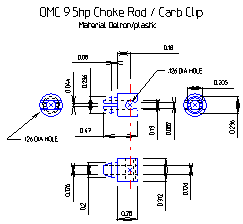
The choke linkage snaps into a whiteish Delron/plastic clip mounted on the top brass linkage, this rod has an Ell on the rear pointing down. This down portion goes into the center hole in the plastic clip and the rod just snaps into the slot in front of the hole. Just pull it up and out of the snap in lips. However if you need to pull the clip, rotate it 90 degrees as the lower tab fits into an elongated slot. Put this clip in a safe location, as the factory parts list does not even list it, so finding a replacement may be hard to do.
You can see this clip in the RH photo below, item # 51 in the OMC parts list #0313329.
Sorry for the bad dimensions on the drawing below, but for some reason, with it being so small, blowing it up looses definition. Maybe when I get time, I can redraw it oversize.
| Here is the CAD drawing of the choke clip mentioned above |
 |
The carb air intake (setting directly on top) is covered by a white plastic cover that has numerous holes in it that just snaps into holes in the carb, which acts as a air filter keeping debris out. It just snaps into holes on opposite sides if the carb.
There are two types of idle adjustment linkages. The early version has a longer shaft protruding from the carburetor that is connected to the knob shaft by a pivoting linkage shaft. The later version uses a flexible speedometer type cable from the carburetor to the control knob in the front panel. It is my guestimate that the reason for the change came about because these powerheads vibrate considerably, especially at a trolling speed. The factory did introduce a anti-vibration kit in 1967 to help alleviate this problem. I will guess that with the non flexible linkage of the previous series had problems that this anti-vibration and flexible carburetor idle system solved.
Also in the RH photo below, bolted to the bottom center of the carburetor is a 2" wide metal strip. This is part of the newer anti-vibration / dampener system, which came out in 1967 and involved some metal with fiber washers and springs. There was also more on the other side of the motor.
| Here are the early carburetor idle jet linkage rod | Here a view of the carburetor, showing the new style flexible idle jet cable system & the synchronization screw head (red arrow) |
|
|
|
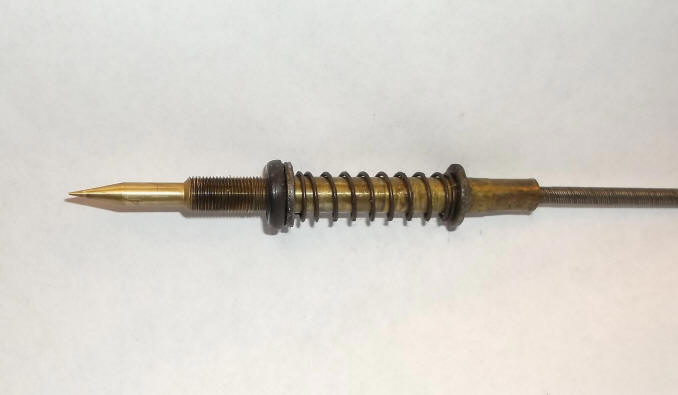
To remove this rich lean adjustment for these later 9 1/2 hp motors, the quick and dirty way is to pull the E-Clip off the flex shaft/needle cable base right behind where it enters the cowling which allows the knob to slide a bit forward out of it's limited rotation. Now you can unscrew the knob/needle assembly from the carburetor, leaving the outer end sliding in the control panel. If you need to then have full access to the needle you will have to remove the knob from the cable, push the cable forward enough to remove as small wire C clip retainer, which will allow it to be pulled out of the control panel from the rear.
For those of you who need dimensions in order to reshape this needle, the thread diameter is .250", with a thread pitch of 40 TPI, the needle rearward diameter is .156", the length of the taper is .430", and the tip diameter is .020" which is flat (no point). The O-ring seal is (best I can measure off the old one) .250" ID, .430" OD which comes out to a thickness of about .093". It may be a good idea to also replace this O-ring while you have it apart as this ring acts as a seal around the shaft. If it is decayed/burred, you may be getting a air leak, effecting the idle.
For the early needles, I don't have these dimensions, but would think the working end of the needle (taper) would be the same as the later ones.
| Here is the idle needle off the later carburetor |
 |
There are two types of float valve needles. The all metal one does not have a clip, the later ones with a soft tip does need the clip. However I have seen transition needles that were the rubber tip but no clip. In addition, the one that uses a clip has a groove for it, the other one does not.
If the lean rich setting control
knob on the front of cowling won't make any change in how the motor runs/not
runs if the idle circuit inside the carburetor is not clear all the way to the
throat of the carburetor. The initial setting for this rich/lean
control should be backed out 3/4 turn from gently bottomed, you may have to
rotate it up to possibly 2 full turns out, but 1 1/2 seems the norm.
The high speed jet is located in the float bowl which is located in the
bottom 1/2 of the carburetor. It is in the hole behind the hex head plug in the very bottom
front of the
carburetor. Takes a well fitting screwdriver to get this jet out without damage.
But if you can see in and this jet is clear and you can blow compressed air
through it, I would leave it alone.
This carburetor must be absolutely, positively,
SQUEAKY CLEAN. And it is very
easily clogged, so may need to be checked often if there is a possibility of
dirty fuel. DO NOT jam wires, drills, or whatever through the
orifice making it larger in your attempts to clean it. This jet is a precision part. The motor will never
work right again if you do.
The original carburetor float is cork, sealed with shellac, they may require replacement if
they become saturated. Or you can go to a hobby shop and buy model
airplane clear Dope, even finger nail polish will work, to recoat the cork. Shellac is dissolved by the alcohol found in
ethanol gasoline. These carburetor floats are not available aftermarket,
but do come with the OE repair kits, part #0382048. Be sure to use the
clip that connects the float arm to the new needle. These clips were not
used on the old float system, and are beneficial to use because of the
possibility of the motor being laid on it's side during transport, the float may
become stuck. This clip pulls the float down when the float bowl is empty.
Also the float COULD get reinstalled upside down, as the pivot arm is not
centered. There is a small lip that protrudes off the brass pivot arm.
This lip is actually a float stop and is designed to bump/stop against the edge
of the brass inlet jet.
To set the float on these motors, with the carburetor body held upside down, the float being viewed from the side, adjust the float so that the free end is level with the hinged end (equal distance front to rear). And when viewed from the end, make sure it is not cocked right or left. This ensures that the needle seats (closes, shutting off fuel) when the fuel bowl is full.
As a suggestion, to do the final slow idle carburetor adjustment, make sure on the boat and on the water. If you are adjusting the low idle in a barrel or such, you could experience inconsistencies. Because in a barrel, the low setting of this engine, the carburetor inhales much their own exhaust which makes it difficult to get a accurate idle adjustment in a barrel unless you have the upper cowling off the motor.
If when priming the primer bulb you get fuel running out the carburetor air intake throat, this is normally caused by a clogged float bowl vent to the outside. This vent hole would be molded into the upper carburetor body. With the bowl off, in the upper carburetor float chamber on the inner side is a hole that will vent the bowl to atmosphere from the upper carburetor outer body. If it's clogged, fuel will find it's way through the high speed jet and out the throat, as the float will never rise to close it's valve.
The main throttle butterfly is operated by a horizontal shaft and a cam off the engine's timing plate when the twist grip throttle is rotated. This shaft is the inner of the 2 shown in the RH photo below. The outer is the idle jet shaft.
This carburetor has a built-in throttle advance when you pull the choke out.
This carburetor being a downdraft model which is susceptible to small things dropping into it and possibly holding a reed valve partially open. If you can not get it to run right after everything else, pull the carburetor and look to see if there is any debris holding one of the reed valves slightly open.
There is no aftermarket carburetor kit available for these motors. The BRP part # is 0382048, which includes the float. Available for $30.96 as of 5-2013. I am disappointed in this kit. It comes with, (like most) repair parts for both the early and late carbs but does not come with everything. On this carburetor, there is a 1/2" core plug on the outer part of the carb that is inline with 3 small holes in the carb throat. These holes had to be drilled through the access hole this core plug covers up. However INSIDE and under the core plug is a plastic filler plug #0312909 that is not included. On the one I repaired, it would be impossible to remove this plastic plug without destroying it. Oh yes, this kit also included a old style fuel pump cover gasket and filter screen.
Instead
of buying a new core plug (even if it is still available) I drill an 1/8"
hole in the plugs, then using an icepick, push it hard into the drilled hole in the plug
and kind of sideways and pry It out. You can
blow anything out of that cavity with compressed air and replace the plug by
lightly peening the hole shut, reshape and replace it with the hole not totally
filled with the metal, Then use a drop of JB Weld to reseal the hole/plug.
There could be many things to cause a poor or no idle
situation, the high and low speed jets for this model must be absolutely clean.
Good enough won't cut it on this carburetor, it has to be SUPER CLEAN, and not
just spraying it with carb cleaner.
The "link and synch" on this motor
is important to be adjusted correctly. In the photo
above the red arrow is pointing to the adjustment screw of the throttle
follower. The shaft that this adjustment screw is on the forward
end of has a tapered section under the screw head, which binds the
follower arm in the set position, which in turn supplies spring tension
on the carburetor follower.
There is supposed to be a mark on the timing plate cam that the throttle cam should be timed to be at when the carburetor butterfly starts to move. You can see the butterfly start to move by using a flashlight, by shining it through the breather holes, you can see the butterfly.
The motor being worked on was missing any indication of a timing mark even with the flywheel pulled off. But it appears to be that the timing plate cam has a dual transition from a flatter idle into a faster taper for high speed. This carburetor cam was set at the juncture of the timing plate transition where the high speed cam sharply increases.
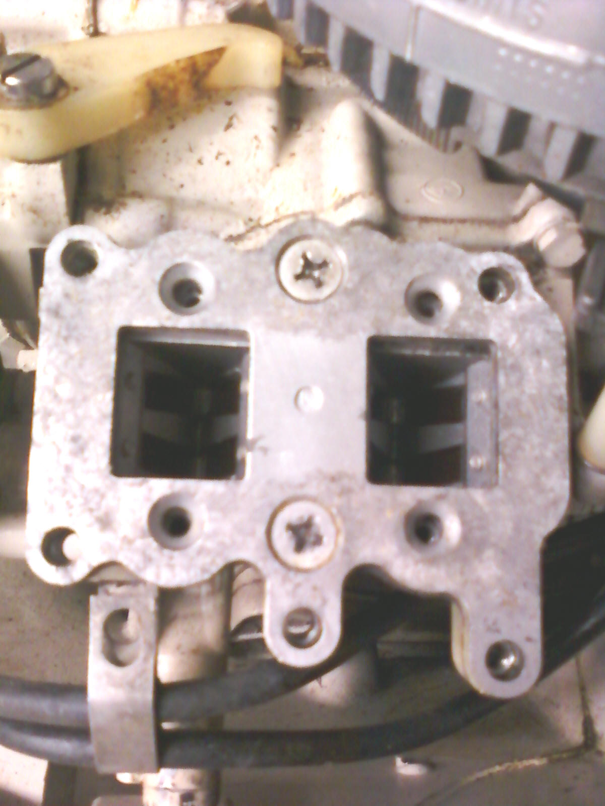
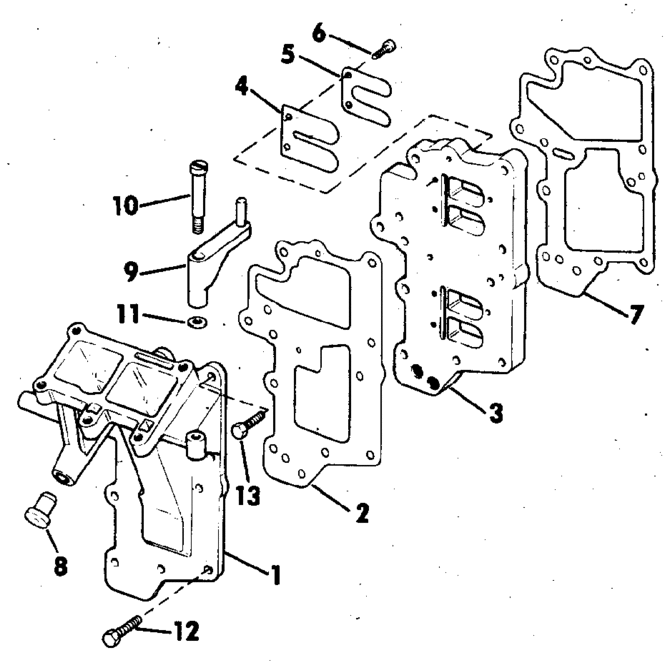
Carburetor Base/Intake Manifold : The reed valves in these 9.5 motors were two different types. The change took place in 1972. Since these are mounted in the intake manifold, this manifold was changed. I have not heard of why this change was done, and I was not mechanicing, or exposed to this motor at that time.
| Here you see the early carburetor base with the reed boxes mounted directly below. At the upper left you can see the slow speed stop arm | Exploded view of late intake manifold and reed valves moved down & closer to the block |
 |
 |
Reed Valve Boxes : As said above, the reed valves in these 9.5 motors were two different types. The early version used a set of reeds mounted in removable boxes that sat under the carburetor base and accessible only from that location. This adapter plate is held in place by two opposing Phillips head screws, which over time could become hard to remove without the aid of an impact driver as seen in the photo above. In this photo the reed box screws were already removed.
| Here is a top view of one of the boxes which has been removed | Here is the bottom view of the same reed box on the left, note the reed stops on the outside of the reeds |
|
|
|
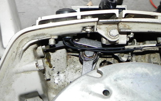
Throttle Linkage : This linkage is rather different and more complicated than you will generally see. The twist grip shaft has a small gear on the rear that engages a gear rack, so as you rotate the twist grip, this geared rack extends or withdraws. The rack shaft then engages a linkage plate that then engages another linkage plate pointing rearward, which then ties to the timing plate. Rather complicated, but it works quite well.
There is also a neutral safety lockout that prevents the motor's twist grip throttle from being advanced past the "START" position. This is simply a rod connected to the internal shifting linkage that abuts against a flathead screw from the twist grip linkage. This screw can be adjusted. However you can shift into either forward or reverse, then twist to a higher setting to start it.
On the late 66 and newer motors there is a idle stop adjustment dial (not to be confused with the rich/lean carburetor adjustment) that is located on the outside of the tiller handle pivot (mentioned below). This dial basically pushes a rod in against the end of the 1/2" rod in line with it, seen at the LH front of the cowling of the photo below, limiting the low speed movement of the twist throttle handle.
| Shown here is the throttle linkage system inside the cowling. The small arm to the right center operates the neutral safety lockout, while the larger arm pointing rearward connects to the timing plate. The wires you see are kill button wiring |
 |
Air Intake : These motors have a separate front panel that sets forward about 3/4" from the lower cowling/pan, which has grated sides, allowing for fresh air to be pulled for the carburetor to breathe, (as shown in the above photo).
Recommended Fuel / Oil Mix : The formula shown below will be on all modern 2 cycle oil sold in the last 30 years or so. On most all of the pints and quart plastic bottles of TWC-3 oils there will be a narrow clear vertical window on the edge of the bottles. On the sides of this window will have numbers representing ounces with Milliliters for other parts of the world. Or you can purchase special measuring containers showing different ratios and the amount of ounces needed.
If your motor is one of these where you have to mix the oil, you need to know how much gasoline you will be needing, add the oil before you fill the fuel tank so that the oil mixes better that just dumping it in after you fuel up. However if that is not possible, guess, and add a majority of what you think it will take, fuel up, then add the rest matching the amount of gasoline you took on. If you are using portable fuel thanks, before hand, when you fill it, add 1 gallon at a time, use a clean 3/8" or 1/2" dowel, mark the dowel at each gallon and then use it as a measuring stick. This way you can refill a partly full tank with the known amount of oil.
Fuel/oil mix on all the OMC motors that have needle roller bearings (this motor included) is 50-1 of TCW-3 standard outboard oil. However I have found that since I troll much of the time, other than getting there and back, I like to use a mix of 75-1 but of a SYNTHETIC blend oil instead of the standard oil. This gives me at least the same or better motor lubrication, plus it gives me less smoke at a troll and the spark plugs last longer before fouling.
A quart has 32 ounces of oil in it. So for a portable 6
gallon tank to fill it using the 50:1 ratio would take 16 ounces, (1 pint) or
1/2 of the quart.
|
FUEL MIXING TABLE |
|||||
| Gallons of Gasoline |
Gasoline to Oil Ratio |
||||
|
Ounces of Oil to be Added |
|||||
| 16:1 | 24:1 | 32:1 | 50:1 | 100:1 | |
| 1 | 8 | 5 | 4 | 3 | 2 |
| 2 | 16 | 11 | 8 | 5 | 3 |
| 3 | 24 | 16 | 12 | 8 | 4 |
| 4 | 32 | 21 | 16 | 11 | 6 |
| 5 | 40 | 27 | 20 | 13 | 7 |
| 6 | 48 | 32 | 24 | 16 | 8 |
Fuel Pump : When the 9.5 hp first came into production, it used a different larger based model fuel pump that had the cover unit rounded. It appears that this fuel pump was short lived (like 2 years) and was used on other motors as well, like at least the 6hp. Repair kits seem to be non-existent.
In 1968 they went to this small square fuel pump. These later fuel pumps are pretty universal, the same one fitting most all these small motors up to 40 hp until about 1987. They are mounted basically the same as the previous versions, on the rear of the block/manifold and extends to the rear considerably below and behind the carburetor. For a link to the later small square pumps, rebuild procedure CLICK HERE.
However it is possible to convert over to the later small square style (9.9hp)fuel pumps #0391667 rather easily as the mounting gasket #0303615 is used on both styles of fuel pumps. In adapting the newer style pump, you will have to replace the two 10-24 X 1 1/2" mounting bolts with 2" bolts. They used the same lower mounting holes as shown on the same LH photo below for the later pumps.
When doing this conversion, you will have to replace and lengthen the discharge hose to the carburetor, then shorten the inlet hose.
There is a junction block located on the opposite side of the motor from the fuel pump that connects the fuel line from the quick coupler on the motor cowling to the line running to the carburetor.
Fuel Filter : When they went to the new style fuel pump on this model in 1968, this pump included a fuel filter (of sorts). As seen in the RH photo below the black plastic inlet is secured by a single center screw. By removing this screw, this inlet cover can be removed, UNDER and pressed into the underside is a fine stainless steel filter screen.
| Here you see the early style fuel pump | Here is the later style fuel pump |
|
|
|
Shown in the photo below is what you see when removing the center screw of the old style fuel pump. This gasket appears to be made of rubber impregnated cork. There are 3 short protruding studs that all 3 have to align and fit before it will align and tighten down on the body.
| Here is the cover cap, screen & gasket for the early fuel pump |
|
|
Idle Stop Adjustment : The 64 - late 66 has an plastic adjuster (Idle stop setting) just rearward of the flywheel (spark plug side) that adjusts the armature plate stop. It has a thumb screw on it for easy adjustment, but you need to pull the cowling off to access it.
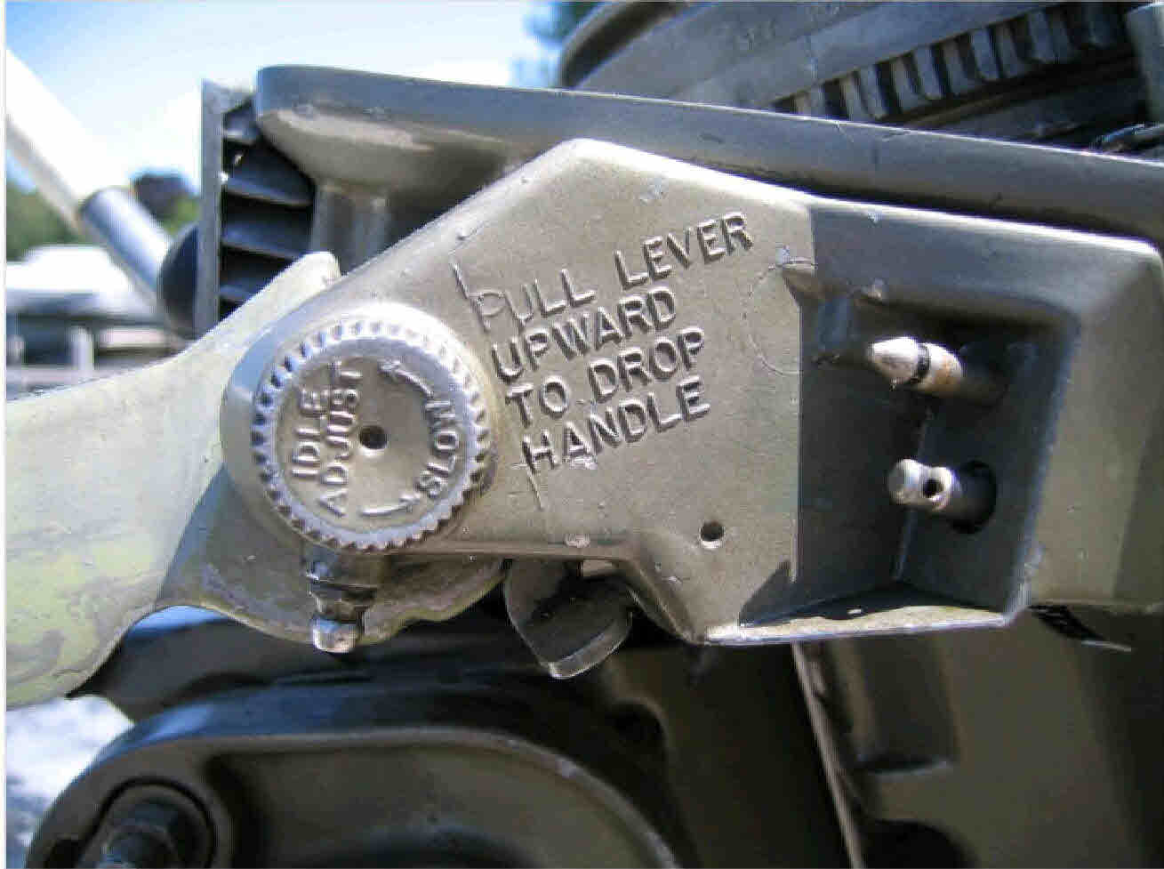
In 1967, the idle speed adjustment knob moved to the base of the tiller handle, next to the fuel coupler. As seen in the photo below, on the side of the base of the tiller handle, there is an idle adjustment knob. Turn that knob to set the idle speed. There is enough friction on the knob shaft to lock the idle speed with the small dial. When this is adjusted this will allow you to return to a preset trolling speed and prevent it from cutting out at low idle.
| Here is an idle adjustment knob for 67 thru 73 motors along with a handle lock lever | |
 |
Dropping Tiller Handle : The tiller handle has a spring tensioned positioner that holds it in two positions.
Below and to the rear is a lever that locks the tiller handle. As seen in the above photo, the tiller handle has a spring tensioned positioner that holds it in two positions. There are cast into the handle base "PULL LEVER UPWARD TO DROP HANDLE". This allows the handle to be raised slightly more, OR lowered considerably more than what the tensioned adjustment normally allows.
If you get to where you need to lower the handle below the horizontal position, (like during transportation with the motor laying on it's side), in the above photo, read the raised words. Right below them is a lever, push it UP, which unlocks a horizontal stop, allowing the handle to be lowered almost straight down. This would be the position I would place it (laying on that side) during transportation.
Tilt Lock:
When the engine is tilted up, it is held in place by the large rod (on the right
when looking at the engine from the front side). In addition, there
is a ratchet mechanism to the left (visible on the attached LH photo below) which
prevents the engine being lowered by it's own weight.
The ratchet is a friction device to let it tilt up easy, but go back down in a
controlled decent fashion. The thru-bolt that goes though the brackets controls
the amount of friction by tightening or loosening the nut. If it is too
stiff, loosen the nut. If un-moveable, take it apart and see what is wrong
with the friction cone part, it may just need to be greased. If this
bolt is seized or broken, new factory ones are not available, but a replacement
3/8" X 8" hex head bolt works. The original threads were National Fine,
but it would be hard to find one of these, so a Standard (course) thread works,
just not as fine of a adjustment however.
The RH photo below shows the motor base trim bracket adjustment. This has gears pinned to the shaft (you can just see parts of 2 teeth in the slot). By pushing in and rotating the exposed wrench activated knob, this geared shaft engages a geared rack that allows the bracket to be adjusted to match the transom angle of the boat.
To Adjust Tilt Angle : Most older adjustment units are hard to move while bearing the weight of the motor, so you need to first tilt the motor up. You have to release lockout to tilt the motor.
The Tilt Lock Selector is located to the lower right of the front of lower cover. The selector pushes the Tilt Lock Rod back to release the motor when in forward or possibly neutral so that it can be lifted up.
The spring loaded locking lever is connected to a wire (reverse lock wire) like part that looks like a bicycle spoke. It is supposed to release automatically when the motor is in neutral or forward gear and only lock in reverse. The adjustment is made to a small barrel-shaped connector on the lower end of the wire. The locking lever prevents the motor from swinging up and causing damage when running in reverse.
Put the shift lever in forward gear (it should work in neutral) to make sure that the motor is released to swing upward on the stern bracket. Push in the tilt lock and raise the motor. Push in and turn the knob to the desired position and return the motor to the running position. You should set the motor so that the cavitation plate is parallel to the water.
Check to be sure that the pin connecting the tilt rod selector to the tilt lock rod is in place or the rod will not move. On some models you can replace them with a small cotter pin. If the pin has deteriorated and you cannot replace it, you will have to reach around and move the Tilt Lock Rod back by hand in order to raise the motor or lower it. There are two upward positions in which the rod can be placed to hold the motor up.
When
trailering with the motor tilted up, you can pull the Tilt lock Selector
forward to lock the Tilt Rod Lock in place.
The shallow water bracket manually swings back to support the motor at an
angle when in shallow water.
As seen in the LH photo below, in the center is a carrying handle (and labeled as such). This motor was the forerunner of this handle, which was later carried over into the 9.9 and 15hp motors.
| Tilt lock ratchet system | Motor base trim bracket adjustment |
 |
 |
Trim Adjustment :
At the
lower right of the above LH photo and the complete RH photo, you will see a knob of sorts that appears to
be made to use a wrench on because of the flats on it. On the RH bracket
near this knob will be "Push In And Turn". Behind the knob is a spring
that lays over the shaft. Attached to the shaft are gears on each end.
These gears engage into notches of the mounting clamp bracket. By
pushing in on the knob and rotating it, you can rotate the gears, moving the
bracket for trim adjustment of the motor.
One thing here, the gears are
small and attached by small (1/16")
roll pins, which are a weak point and can result in a broken gear. If
you have to replace a gear,
the knob along with both gears are held onto the shaft by these roll pins,
which need to be driven out very carefully.
Steering Friction Adjustment : There is a friction plate directly under the powerhead cowling in front of the block. This plate is made of a arced steel plate with a arced slot in the center. There is a bolt with a friction washer going down thru this slot as shown in the above illustration. The bolt head is hex but also has a screwdriver slot in the top. With the upper cowling off and the motor centered pointing forward, you can reach down thru an access hole with the screwdriver then adjust this friction so the motor does not wobble back and forth when running at a idle.
| Exploded view of swivel bracket |
|
|
To Start
: The most
common setting to start these 9.5 motors are with the twist grip handle turned
up counter-clockwise to the neutral stop and with full choke, then after the
engine warms up, ease it back clockwise to "shift" position.
Start in Neutral / Shifting Adjustment : This motor, like many, has a gear lockout feature where the motor needs to be in neutral or forward to be able to start. When in neutral, the there is a stop that limits the RPM of the motor. If it is then shifted into reverse, the peg is in a different location but also is a slightly higher rev limiter in reverse. However, you can start it in forward, with no limitation as to RPM. If you look at the photo below, the green arrow points to a slotted head screw under a peg on the shifting linkage. This screw can be adjusted to act as a bumper stop for the shifting linkage peg.
If you need to make any adjustment in the position of the main shafting lever OR to adjust the above mentioned rev limiter, this is done using the bolt indicated by the red arrow. Or if you can not get it adjusted, and have to start it in Neutral, then remove the linkage bar.
However this adjustment does nothing for gearbox
shifting, where you may have worn clutch dog ears or mating gear notches.
The shifting lever itself is as indicated in the photo below by
the purple arrow. The twist grip throttle speed indicator is seen in
the right hand photo below.
| Here you can see the shifting linkage adjustments | For those of you who have the words obliterated, here you can see Fast-Start-Shift-Slow |
|
|
|
Shift Gears : On this model, the shift handle is on the outer starboard side, (front RH looking forward). The positions are up for reverse and down for forward with neutral in the center. The front panel of the motor has R/N/F printed vertically on the RH edge as seen in the photo LH below.
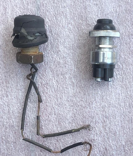
Stop Button : As seen in the photo on the left below there is a rubber covered button the size of a 1/2 dollar on front port (RH) side. This push button was impossible to save AND now sells for $30. BUT if you go to your local automotive store and get a push button starter button, Pico #5509PT, the button itself is smaller, is weather resistant, has screw type wire connections, and fits in the hole and functions.
The wires from/to this button use plastic quick disconnect couplers to the magneto. This button just grounds out the ignition, killing the motor.
| Here the old kill button on the left with a new replacement on the right |
 |
Remote Controls : It apparently was not originally designed for remote controls, however I have seen an aftermarket version and the one shown on the left below did appear later on OMC literature for accessories. This is evidenced by the taller shifting lever on the motor in the photos below. From what I see, it would be hard to convert this motor to remote throttle cables.
| Evinrude 9.5 front view | Johnson 9.5 front view |
|
|
|
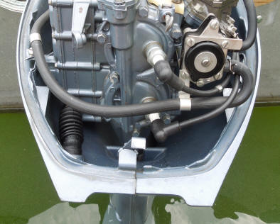
Upper Cowling : There were 2 different type of cowling latches, a twist lock that was made only in '64 and '65. They moved the release lever into the lower cowl in '66, but pretty much all the other parts on that are interchangeable.
| Here is a rear view of the early cowling latch & early fuel pump | Here is a side view of the rotating latch knob |
 |
.jpg) |
| Here is the late cowling latch & late fuel pump |
|
|
Lower Cover : These motors utilized a split lower cover that surrounded the exhaust housing. This feature compounds repairs where a simple part may need to be replaced, but the whole cover needs to be removed to access it.
Vibration Dampener : This powerhead does a lot of shaking when running at a trolling speed. In 1967 it came out with a dampener system, which involved some metal brackets with fiber washers and springs. There was one mounted on the starboard side being attached by two of the carburetor base bolts. The port side unit was buried up under the recoil starter. These were attached to the motor and with the other end to the inner part of the side skirts. It appears that this was their cure, without changing any other parts.
A reader of these articles found a New Old Stock retrofit damper kit and installed them on his motor. He said it was a much easier job than he had anticipated. There is adequate room to slip them in on the starboard side, and also on the port side after the starter recoil unit is removed, without other major parts removal. The only real issue was where to drill the mounting holes in the shrouds. Fortunately, the retrofit kit came with OMC templates for this. Having used it once, he does not believe that it is truly necessary, as even after being exceedingly careful in using the template to locate the holes, they (the holes) looked to be almost 1/8" out of the ideal position. He actually thinks one could do as well to pre-assemble the two units, lightly bolt them in place and then carefully estimate the places to drill.
Exhaust Housing : There is a rubber corrugated boot (as seen in the LH side of the photo below) that connects the exhaust housing to the outer middle cowling exhaust water outlet. This boot is notorious for becoming cracked and when this happens, you can again get exhaust gasses inside the engine cowling creating the same problem stated above. One way to test for this situation is to remove the cowling and then see if the idling improves. You may still get some contaminated air into the carburetor, but at least you have increased the odds of it getting better clean air. Your best option is to take it the lake or pond, then adjust it on the boat under a load, or if you must adjust it in a barrel, get a fan to blow the exhaust away from the motor and barrel because in a barrel you do not have as much a chance to dissipate any exhaust gas that the engine may be re-breathing.
With reference to the above issue, make sure it runs and idles properly with the hood on ... another common problem with no available parts. However IF you can find a replacement boot it is not that hard a job of replacing it. The boot is held onto the block by a large snap clamp and is just inserted into the hole in the outer exhaust housing. A tip to install it, is to lubricate it with some soapy water. It goes into a hole slightly smaller than the outer end of the boot, which snaps over the outer part of the hole, holding the boot in place. If none can be found, then try good old electricians tape.
Also on these 9.5 OMC motors the factory finally identified the situation where running in a barrel, where there was no air movement over the motor to suck fumes away that with the carburetor's air intake setting next to the flywheel, that this flywheel rotation during running, created an air disturbance into the carburetor. Some mechanics would drill a 1/2" hole in the upper cowling above the carburetor throat to allow it to breathe better. They then my bolt a small clamshell over the top to keep water out.
| Notice the bellows type rubber boot on the lower left |
|
|
Also on these 9.5 OMC motors IF the above mentioned grommet is really bad, (and it is usually underneath so not really visible) you could also get a water buildup between the inner and outer housings. It may drain out over time, but if you live/boat in a freezing climate, this could possibly create problems.
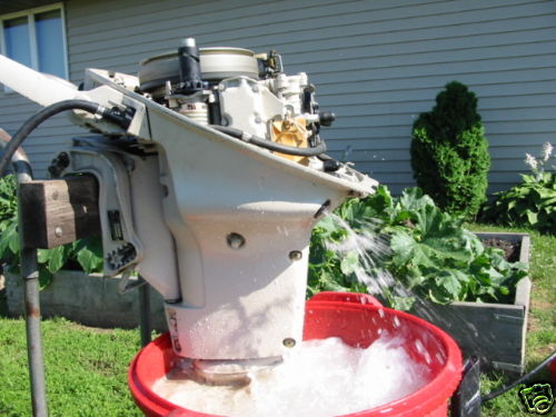
Exhaust Water Indicator : This model doesn't have a overboard water indicator telltale "pee hole" like later models do. But there is a corrugated rubber boot hose(mentioned above) attached to the back of the engine block which comes out the back of the engine casing just under the cowling. You should be seeing a healthy broken-up water spray as seen in the running motor in the red trash can farther down in this article. At higher speeds, less exhaust comes out, so the water sort of runs out.
| Here is a running motor, notice the overboard water blubbering out the rear |
 |
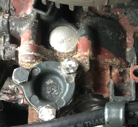
Water mix will only spray out that hole when the thermostat is open. So until the motor warms up, it should be dry for possibly the first minute or so when started cold. In the photo below, you will see the thermostat cover plate held in by the 3 bolts.
| Here you see the thermostat cover |
 |
Water Intake : These motors main water supply to the water pump comes from a screened tube right behind the prop in the exhaust outlet. Water is forced into the screened intake to the water pump by the prop thrust. Some users report that when running these motors in a barrel, (usually a small one) that the prop has to be installed and usually in gear as apparently they need to get more water pushed to the water pump by the prop to get enough to cool when running at over an idle.
There is a also a stainless steel intake plate with a few holes near the water pump area on the left side above the cavitation plate shown in the photos below. Flush kits for this motor are rather scarce. There is really no provision currently available for a easy muff system to run this motor out of a tank. But there is hope.
Water Pump : The operation of most marine water pumps using a rubber vaned impeller is, the cavity between the vanes is what makes it pump water. As the off-center impeller rotates, the cavity enlarges, drawing in a gulp of water. As it continues to rotate, the cavity becomes smaller, and squeezes the water out and up the water tube to the powerhead.
These pump housings are pot metal, and can become
pitted, replace them with a new water pump assembly if needed. There is
also a stainless bottom plate, this plate has to be positioned with the suction
hole in the proper location/relationship as indicated in the photos. If you
are just replacing the impeller, you can tell which way is up by observing the
wear of the impeller on this plate. The impeller fits in this stainless cup
liner which gives a very long lasting situation. In most cases you will never
need to replace the water pump assembly, just the impeller.
Also changing the water pump impeller is not as easy as the others because the water supply tube to the powerhead will many times come undone at the powerhead which it is a problem getting it back in place.
BTY, the impeller is Sierra #18-3003.
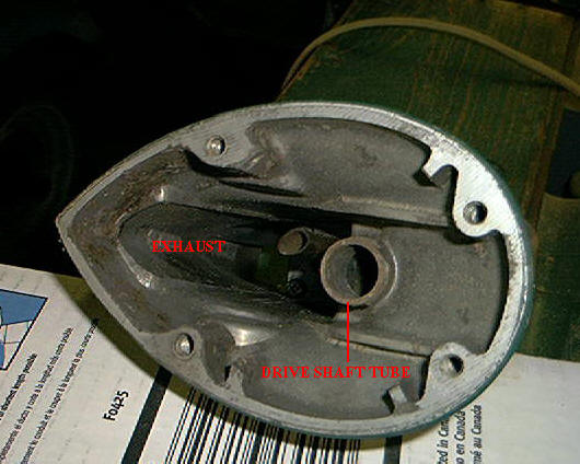
| 9.5 hp impeller installed in upper housing before final assembly | Here is the bottom view of the exhaust housing that bolts on top of the water pump. The water tube seen in the center goes into the top outlet of the pump housing |
 |
 |
There is a rubber grommet at the top of the water inlet tube where it enters the lower part of the block. There is the possibility where this grommet may become decayed to where a good connection may effect the water flow into the motor, however this appears rare in the real world. The water outlet from the block apparently just exits into the exhaust housing cavity, which creates cooling and eliminating paint being burned. This exhaust water blubbers out the single hole in the upper rear of the exhaust housing along with some exhaust. There is no water overboard tell tale like on the later motors, only this misty water exhaust mix.
One thing to realize is that this exhaust blubbering may be more until the motor warms up enough to open the thermostat.
Water Supply Tube : This copper water tube from the water pump to the powerhead is retained in the exhaust housing, just below the powerhead by a stainless steel push nut. A washer and O-Ring then completes the seal with the powerhead. If this tube gets pulled out of the push nut, it may be almost impossible to reinstall it without removal of the powerhead. You may luck out by using a flash light and look close you'll see where it came from and with a lot of luck may be able to reinsert it, otherwise you may have to pull the powerhead.
And this removal of the outer housing is a very complicated job for the novice. The outer shell has to be split open and the motor comes out so you can get it apart. Lots of screws, links, and stuff. Really not bad if you know what you are doing, but for your first time, it will be a challenge. The good part it is not needed to be removed to do any gearbox repair.
Aftermarket Water Flushing Adapter Cover : These motors main water supply to the water pump comes from a screened tube right behind the prop in the exhaust outlet which utilizes the thrust from the prop to push water up to the water pump. This method of water intake does not allow the newer type of flushing muffs to be used. Flush kits were made for a while for this motor but now are not currently made and are rather scarce. But there is hope.
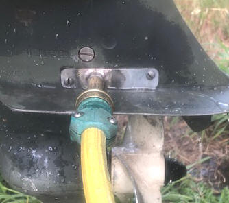
On the LH (port side) of the exhaust housing just above the anti-cavitation plate there thin stainless steel plate (the factory nomenclature is water bypass cover) which is held in by 2 screws. In this plate are 4 small clamshell type scoops that is designed to put water into the water pump when the motor is in reverse, as shown in the photo on the left below. This is common to many different size of these motors up to 10hp in these years up to about 1974. It was designed to supply water to the water pump when the motor was in reverse, however some motor owners think it is there for added water intake during forward running so you may see them in stalled either way.
The right photo below is a copy of a commercial aftermarket adapter (no longer available) with a 3/8" course thread nut welded onto a similar sized sideplate. This allows the usage of Mercury's Quick-Silver Flushing Device described below. These flush plates apparently was NOT designed to be used when running, only for flushing. Since these are no longer made, you can fashion one by using the original plate as a sample and soldering/brazing, (even epoxy) a 3/8" course nut onto the outside of it to screw the flushing adapter into. Or there are some of this style available online.
| Evinrude with original reverse water inlet plate |
Here this home made flush plate adapter
in use |
|
|
 |
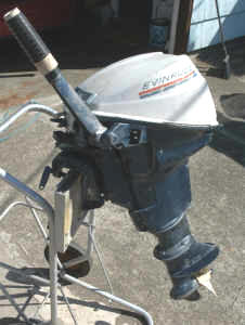
Shaft Length : Most of these motors you will see are short shafts, however they did make a longs-haft as shown in the photo below. From what I can tell by checking parts lists, it just uses a long-shaft 5" extension off an earlier 10 HP QD motor.
| 9.5 long-shaft motor |
 |
Lower Units : One thing that may complicate removal of the lower unit (IF IT IS A LONGSHAFT version) is it is possible there could be (2) shifting rod couplers, (1) at the lower juncture of the midsection with the gearcase, (2) a second one at the juncture of the midsection AND the 5" long shaft extension. If this is the case, the lower unit WILL NOT come off until you also remove the screw from the upper coupler. Needless to say, remove the upper one first.
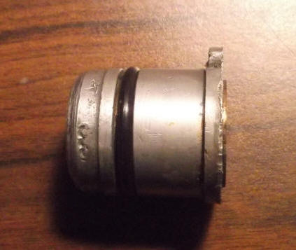
The lower unit appears that they actually use the FOUR BOLT lower unit (gearcase) off the previous 10hp QD series on these 9.5 hp motors up until 1967 as backed up buy NAPPA's parts catalog. Which identifies the B suffix from 58-67 seal kits #18-2682 and the prop shaft seal #303345. Where it shows the M suffix covering from 67-73 for the seal kits 18-2683 and prop shaft seal #313282, with the main difference being the prop shaft seal outside diameter (unless there is a typo in the NAPPA catalog and the suffix numbers got reversed as observed below). These seals are shown in the exploded view illustration below as #43, with the O-Ring #44 and the housing #42.
Now comes the confusing part, I have a couple of neighbors, one as a 1972 Evinrude model 9322B and the other also a B series which both have the prop shaft seal using a shaft diameter of .554", OD 1.062", width .312" where the seal is definitely #313282, (as seen in the photo below) NAPPA / Sierra # 18-2023. This appears wrong for that year of motor if you go by the NAPPA listing, UNLESS the two bearing housings will interchange and the later one was used to replace the original. However I would have thought the "B" in the model number would have indicated otherwise, so my idea of NAPPA being wrong seems to bear out .
The other seal seemingly used on the M series is #303345 and has the same shaft .554" dia. but smaller OD (1.00") and wider .375", NAPPA / Sierra # 18-2022. Now considering the NAPPA ID numbers, usually the earlier/lower part number would pertain the the older version, again pointing to my idea of the flopped suffix letters, where this other NAPPA # is 18-2023 for the larger dia. seal identified by the photo below.
As mentioned above there seems to be some confusion as to the seals for this model, (shaft size is the same for either) verified by the parts listing from the major parts suppliers who do not even list this seal. Seals are not made by OMC, but major automotive/industrial suppliers, so my thinking here is these marine parts suppliers don't know for sure, so simply don't list it to avoid confusion and possible returns. And there is not a lot of old mechanics still alive to give insight to this mess. And the aftermarket service manuals do not list anything on this model that I have found.
Possibly if you could find a late 9.5hp (67 to 73) factory service manual it could shed some light on this issue. I may be off base here, but that is about the only thing that seems to add up. So it seems the best way to be sure you get the right seal is to measure the OD of the seal which is the main difference. My further guess is the reason for the seal OD diameter change was that the early 1" OD had over time and conditions proved inadequate and leaked, so they increased the OD allowing for a better actual internal seal design.
To remove this seal, you need to go in from the front with a punch large enough (3/8") to be able to get a good bite on the inner part above the neoprene seal and drive the whole seal out. Clean the area good and with a flat steel bar covering the seal, with a hammer tap the new one back in the recess.
In reassembly be sure that the shifting yoke upper arms engage the slots in the shifter slider. To accomplish this you may have to remove the cotter pin and retainer pin at the rear to get these arms engaged, then replace the pin and cotter pin.
While you are there you might as well replace the rear bronze bearing housing O-Ring also (1.062 ID X .125 thick). NAPPA / Sierra # 18-7117, which appears to be the same for either bearing housings. It is best to clean the bearing housing and replace this O-Ring when you have it apart. Do not put a lot of aftermarket sealant on this housing as the O-Ring does that purpose. If the spaghetti seal is good enough (not missing or damages spots, you may get by with only smearing a light coating of sealant on the two gearbox halves.
In the RH photo below you can see the O-Ring seal and just a slight amount of the #313282 seal protruding out the rear (LH side).
| Here you see the rear of the bearing housing/carrier and the seal that is pressed into the rear & the new O-Ring to seal the outer part of the housing | Here is a side view of the bearing housing/carrier with the O-Ring in place |
|
|
 |
You will probably not be able to screw the shifting yoke pivot screw into the hole in the yoke until you have the bottom 1/2 of the gearbox bolted back on. Then using a flashlight and an ice-pick, align the yoke so you can then carefully get the screw in. If after you have it in, you do not have forward and reverse, pull the pivot screw out and try again.
Also it appears the driveshaft seal is also different between the two versions.
As mentioned prior, since this gearbox is essentially the same as the 10 ho QD series, anything mentioned here should apply. This would also apply to the smaller 6hp gearboxes, but with a slightly different rear bearing/seal housing alignment securement which is a small peg that has to align with a hole in the upper housing.
Gearbox : The lower unit gearbox is the same basic design as most of the OMC motors (larger and smaller) of the same close yearage that has a separate bottom section that when the unit is turned upside down, exposes all the gears and output shaft. There is a spaghetti type O-Ring that seals the grease in the lower unit when assembled.
| Here is what a boater does not really want to see, bad saltwater intrusion & completely rusted beyond any use. | Here the gearbox is removed from the motor & the lower 1/2 also removed showing the gears & shaft bearings. Note the 3/16" hole in the shifting yoke. This is where the Allen headed PIVOT screw goes thru. |
|
|
|
When you reassemble the shaft and shifting slider dog, be sure that the slider yoke is positioned as shown above. Also the bearing housing has a hole that engages a peg in the upper housing that secures it and keeps it from rotating, be sure that is in the right place before you tighten down the cover.
This gear case does not use a regular gasket, but a spaghetti rubber seal is .100" dia. allowing the two metals to mate tightly. This seal is purchased in bulk so you cut off just a bit more than you need. For this model 11" is enough. This seal is the same as used on all the other models that have the split gearbox, it may just be a different length depending on the size of the motor. It may do the job alone, but OMC recommended it's 3M 847 sealant, but it's kind of pricey hard to find at regular stores. Lots of folks use Permatex #2 Ultra Black with good success and it's available at almost any auto store for just a few bucks. The main thing is that you want to keep it watertight. Also when you lay out the rubber seal in the groove, cut off just a little longer than needed as it will spread out in groove when housing is pressed together.
When reassembling these gear cases, you should use some gasket sealant on the spaghetti seal itself, both surfaces of the clamshell gear case as well, especially around the bolt holes as well as the perimeter of any oil seals.
If you can not find outboard gear oil, go to a automotive store and purchase 80-90W gear oil. This would be as close to what the factory originally used. I use the same oil in my rototiller gearbox.
Shift Lever Detents in Gearbox : If the motor pops out of forward gear, there are positive click stop notches in the shifting lever there is an Ell shaped bent spring that snaps into these notches on the shifting rod, putting tension holding it in place inside the lower unit (#26 in the exploded views above). This spring and a helper spring are screwed into the lower unit above the prop shaft which the spring detent mate into notches in the shifting rod. If your motor's shifting rod stop is non-functioning, the spring and helper could be in fine shape, just that they had gotten slid out of position enough to not engage into the rod's notches. So this could be just a simple matter of realigning them then retightening the screw once the gearbox was apart. Notice when tightening the spring, the torque of tightening the screw rotates the spring, (as seen below) where this spring is slightly misaligned, this needs to be straightened before reassembly.
Also in the photo below, with the bottom section of the gearbox removed along with the forward and reverse gears and the prop-shaft, you will note the shifting rod is arced around the LH side of the gear unit and a cotter pin which attaches it to the shifting yoke.
And, notice the 1/8" peg in the center of the front bearing recess. Upon reassembly this peg goes into a recess in the front bearing housing to keep it from rotating. If you do not get this to align in the bearing's hole, the bottom 1/2 of the gearbox will not be able to be tightened properly.
| The red arrow pointing to the area of the notches on the rod where the flat spring engages to secure it when in the selected gear. This is typical of many of the OMC gearbox shifting detents of this era |
|
|
Worn Clutch Dog Slider : If the clutch dog slider (#37 in the exploded view below, left) has become worn, this can also cause the motor to jump out of forward gear, which gets worse as the load in the boat increases.
If this is the case, new ones are impossible to find and good used ones are getting scarce. Some will tell you to reverse (flop ends) the sliding clutch dog unit. Sorry, but this will not really work, well maybe for a while if it is not really worn, because the drive side of this dog for forward will also be the same side as when you flop it where you will then be using the same edge for reverse. Worn is bad in either case.
I happen to be a retired machinist and still have a fairly
complete machine shop. For the well worn clutch dog shown below, I welded up the leading
edges of the dogs with a E9018 electric electrode rod, then ground them close by hand, doing the final fitting with
a Dremel tool and 1/8" carbide cutter.
Then I re-heat treated it by heating the whole end lug part to a dull red,
quenching in transformer oil and the drawing that end back by first polishing
it, then drawing that end back until the color just turns light blueish/purple.
Then let it air cool.
For the forward gear, which was worn just as bad, I mounted this gear in my milling machine and using a 3/8" carbide end mill, then recut the bad corner back about .040". Then did the same for the opposite side and by measuring the first as close as possible and trying to match it on the second. The reverse gear was treated the same. There is a lot of clearance/slop here for the clutch dog slider to move into, (to accommodate smoother shifting) and this extra .040" would not make any appreciable difference.
If you are handy with a Dremel tool and using an 1/8" or 1/4" round Carbide cutter, you can do basically what I did mentioned above and just move the clutch dogs leading edge back so they are as close to the same dimensions as possible.
| Here is the worn clutch dog as seen on the top RH & bottom LH edges | Here the worn areas have been welded & hand ground to match close to the original shape | Here you can see the bright machined area on the RH edge (drive edge) of the forward gear |
|
|
|
|
There is a small magnet inserted in the upper rear of the lower unit near where the rear propshaft bearing/seal housing nestles. There is also a ear on the bearing housing that prevents it from rotating that slides into a recess near that magnet.
| Exploded view of gearcase |
 |
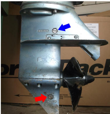
To check the oil level on these lower units, like most all of the ones that follow, there are two stainless steel flat head screws on the port (LH) side (#17 in the illustration above) . One is down below with the prop shaft and the other above the cavitation plate. The upper screw is the access hole for visually checking the oil level, and the lower is for putting oil into the lower unit and as seen in the photo below, the level is indicated by the blue arrow while the fill plug is shown by the red arrow.
The oil normally used is a 90 weight gear oil. It could be regular or synthetic oil. You can drain the oil by unscrewing both screws and allow the oil to drain out. If you are just topping it off, leave the upper screw in until you get the oil filler pump adapter threaded into the lower hole. Then remove the upper screw and pump oil into the lower hole until it starts to flow out the upper hole as seen in the photo on the right. It is best to replace the Nylon seal gasket under these screw heads at this time also. Replace the upper screw first, which will then lessen the chance of oil running out the bottom hole somewhat until you can get the lower screw and gasket screwed in.
| Oil fill & oil level screws | Here a lower unit of a 9.9hp being filled, notice blueish oil coming from upper hole indicating it is full, the principle is the same on the 9.5hp |
 |
|
Prop : This prop is a NON-THRU THE HUB as seen in the LH photo above, and uses a shear pin (3/16" dia. X 1.380 OAL) through the shaft as a driver.
There seems to be a lot of confusion on these props.
In the early/mid 1970s OMC offered a accessory Lexan prop for the 9.5 hp. That is all they offered for a short time was the replacement 3-blade, 8 1/8 diameter, 8" pitch prop (part # 0385940) using a 9/16" center hole, but later they dropped them and reverted back to the aluminum props, #0763588 8-1/4 X 8 and currently available new at about $150. That same prop was also spec'd as the replacement prop for 1958 - 63 10 hp motors.
Then here is what I found on a 1973 Evinrude that this prop looks a lot newer than if it was original, 8X7 J and #397333D/2 (the D/2 is smaller than the rest and I have no clue as to it's meaning).
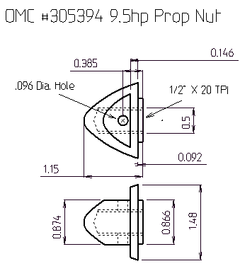
Prop Nut: This is a plastic cone shaped nut, shown as illustration #49 above, #0305394 and is threaded for 1/2" X 20 TPI (National Fine). It is still factory available for a price of $40. It has a flat on 2 sides of the rear for ease of threading it on, with a cross hole for the cotter pin. Or you could use a standard 1/2" NF nut with a hole drilled for the cotter pin. If using just the steel nut, you may have to use flat washers under it and between the prop itself to allow it to be tightened properly and rearward thrust.
In case you did not realize it the nut is only there to keep the prop on when in reverse. You could start up and run all day long in forward gear without the prop falling off, but put it in reverse and the prop will fall off.
| CAD drawing of #305394 nut |
 |
Exploded Parts Lists : If you need to check on parts but do not have a actual parts list booklet, one of your best sources is http://www.crowleymarine.com/ They have a complete listing of about all of the Johnson and Evinrude motors showing exploded parts views with part numbers and you can order parts online from them.
Comments : I have found that I try to purchase factory SERVICE manuals for motors that I work on, it saves lots of time on my part. Well for this model whoever wrote the manual for this motor NEVER worked on one that had been in the field. Totally missing is anything detailed in the throttle linkage system (which is complicated). Also very LITTLE is given on shifting/throttle/gear lockout.
copyright © 2009 - 2025 LeeRoy Wisner All Rights
Reserved
Back to the Ramblings
Home Page
Originally
stated 06-19-2009, Last Updated 03-02-2025 *
Contact the author