|
|
Maintaining Johnson/Evinrude 9.9 & 15 hp 2 cycle Outboards 1974–2007 ( Powerhead / Midsection ) |
|
Note -- some of these articles have pictures
that require a possible long load time, especially if you are on a dial up
connection
Motors Covered Here : This section will cover all the 2 stroke 9.9 motors but keep in mind that there are slight differences between the pre 93's which are minimal, but the procedures are the same, just possible different parts configuration. The pre-93 blocks used heads with the spark plugs on the RH side, while the post 93s had the spark plugs on the LH side of the head. The upper motor mounts are also different between the pre and the posts, but in the same location and do the same thing.
This whole series of pre 93s 2 stroke motors are looked at by knowledgeable boaters as being nearly bullet-proof.
The post 93s are sometimes referred to by OMC mechanics as large block 9.9s. They are somewhat easier to work on because the plastic lower side panels can be readily removed. There is a complete new rope starter assembly than the pre 93s had. And on the tiller handle, the shifting unit/electric starter button are totally different.
We will look first at issues where you do not have to remove the powerhead. Or at least you will be able to get some indication as to the internal condition of the motor.
Replacing the Points : If your motor is the magneto ignition found on the 1974 - 1976 motors, when replacing the points be extra careful and INSPECT the new points by comparing to the old ones you took out. I fought one of my motors for more years than I care to remember. It would run, but not idle down and die at about 1/2 way through the twist grip throttle/timing plate movement. I do not remember how many times, I got so irritated and set it back for a later date. It was timed 33.5 degrees fast. The wear bar was overly long as compared to the one on the old set.
Before I removed one of these sets, I adjusted it to where the flywheel timing mark were on. I cleaned up a old set of points and installed them without changing the flywheel movement. Adjusted the points to where I just got a break in continuity. And then, rotated slightly using a multi-meter again checking for continuity to disappear. It was right on the proper flywheel mark.
When looking at OMC points listing, the same points fit ALL their magneto motors EXCEPT the 9.9/15hp motors. I am sure somewhere along the line SOMEONE placed the wrong set in the box, or picked the wrong set off the shelf.
Replacing the Thermostat : It is advisable if you are having water pumping problems to also take a look at the thermostat, since if the water pump impeller had gotten any of the vanes worn off, this is a location that this chewed up vane rubber material can collect anywhere in the cooling system and plug things up. If your motor is older, you may consider replacing the thermostat anyway. The word is that the newer thermostats are constructed of a better material and operate better than many of the older ones.
Thermostats were put there for reasons by the factory to regulate engine temperatures and insure that the powerhead heats up to normal temperatures. There are a couple of concerns regarding running without thermostats. (1) The thermostat acts like a restriction in the water system. It forces the whole engine block to fill completely with water before any of it exits into the midsection. This way, the whole block gets cooling water. If you have no thermostat, the cooling water can escape the block too quickly and might cause hot spots in the block, especially at the top of the engine. (2) Running with no thermostat can cause the engine to run too cool. Cool running engines have poorer combustion. This condition can cause long term issues. Cold running engines (especially a 2 cycle) tend to accumulate carbon around the rings quicker than a warm/normal running engine. Carbon accumulation can cause starting issues and poor fuel economy. Worse, it can cause a powerhead failure over a long period of time if too much carbon accumulates on the rings.
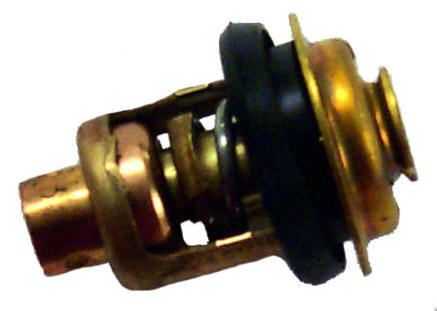
| Standard thermostat used on many motors |
 |
The thermostats are supposed to open at about 160 degrees F. which will allow
the head to heat up just above the point that you will want to hold your hand
on it for much more than a minute. If it gets hot enough that you can smell
burning paint, shut it off as the motor is too hot.
On the motors before 1986 this thermostat is located in the lower portion of
the outside rear water cover, which is bolted onto the rear of the head. The
thermostat is in the very bottom of this cover. The cover can be removed from
the motor without removal of the power head. BUT you will have to remove the
rear cover latch to allow enough room to access the lower RH cover bolt to be
able to remove this cover. It can be almost as easy to remove the complete
head and thermostat as a unit instead of fighting the latch closeness, (SEE HEAD
REMOVAL BELOW).
This can be a little tricky in that you need to keep unscrewing the latch screw (1 flat at a time) from the inside, pull the latch lever rearward so that the screw is totally unscrewed allowing the lever to be retracted rearward out of it's hole. You may have to modify a wrench by thinning it as there is minimal room. Once you get it about 1/2 unscrewed you can hold onto the bolt head and unscrew the latch lever. Now the inner actual latch can be pulled out after it falls off the screw, which then the screw is free allowing the thermostat cover to be removed.
The problem for reassembly is usually that the wafer washer is hard to get aligned over the lever shaft AND then get the latch aligned with the flats coinciding with the flats on the shaft all at the same time. I have found it easier to get the bolt along with the flat washer angled in place and then have someone with skinny fingers place the latch and wafer washer over the bolt while the bolt is then poked rearward but not out the hole. At the same time push the lever/shaft in the hole, trying to align everything. Rotate the lever as much as possible trying to get at least one thread started. Don't worry about the placement of the latch until you get the bolt pretty well tightened, but still allowing clearance to slide it onto the flats. Once you have the threads going, you can rotate the lever & at the same time tighten the bolt head with a wrench, speeding up the process.
Better way submitted by John Modic. Make up a piece of all-thread the same overall length as the original bolt including the head. LocTite the threads into the latch lever, line up washer and latch on the inside, push the lever with the all-thread bolt in from outside and place a nut on the end of the threads, tighten the nut and you have saved a lot of frustration.
When reassembling, you also have to have the bottom RH bolt inserted into the thermostat cover before you slide it into place as there is not enough room to do it once the cover is in place. You also need skinny fingers to be able to re-attach the engine cover latch to it's lever properly. It will generally be best to get the screw mostly into the latch lever before you try to align the latch flats to the lever.
Cable Type Throttle Linkage : Motors after about 1986 eliminated the gear disengage problem by going to a cable throttle linkage system instead. The photo below shows a 1992 with the kill button on the side near the twist grip. The earlier kill buttons were on the end of the twist knob, but the cable system was the same.
If this twist handle seems to not want to move, the cable may be dry and binding inside, or the timing plate may also be dry and dragging. To test this, remove the ball socket end of the cable at the timing plate, now see if the handle will now twist. If not, then the problem is in the cable. You may be able to remove the cable, then get some penetrating oil in to lubricate it.
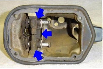
To disassemble this unit, you will notice a small round hole (about 3/16" dia. ) at the arrow. There is another 180 degrees and on the bottom. You need to use a couple of punches, depress both of these at the same time, while pulling the handle off front-wise. A helper can be useful in this instance. Inside this plastic is a dual rotating cam slot which a center cross-pin enters into spacers, and rollers (illustration # 3, 18 and 20 as seen below) which is in turn attached into the cable end. When disassembling this handle, be careful to not loose these spacers and rollers. With the center pin removed, this cable needs to be pulled outward through the handle.
When twisting the handle, the cable moves in or out. This outer cable rear end is then secured by a pivoting ball in the lower cowling. The rear inner cable has a screw on adjustable end attached to a small ball socket on the timing plate. You can make some adjustment in this linkage by moving the threaded ball on the outer threaded cable, and or at the cable rear end. If you are replacing the cable, be sure to set the ball and cable end at very close to what the original cable settings were, otherwise you may never get it set right, using a guessing game.
| To disassemble, push in on the 2 plungers simultaneously (top & bottom) & pull the twist handle forward. This reveals the slider cams. |
|
|
There is a black plastic twist knob on the end of the twist handle. This is a slow speed idle stop, (NOT A CARBURETOR IDLE ADJUSTMENT).
This can be tricky to get set UNLESS the cable is adjusted properly on the low end of the speed setting. And many times not worth the effort.
| Exploded tiller handle for cable throttle control system from 1986 |
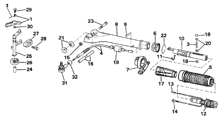 |
| To access the parts list for the above illustration CLICK HERE |
One thing you may look for in the cable system, is that on the end of the cable
where the nylon socket is that attaches to the ball, is this cable end seems to
rotate slightly depending on the position of the handle's height. The
nylon socket is threaded onto the end of the cable's shaft. You may have
to thread it on farther or less to position it so the socket is about level with
the handle elevated slightly, otherwise if it twists far enough it may pop off
the ball.
If this
cable is not adjusted right you might have hard starting when putting the twist
grip at "START". Incorporated in the end of these twist grip handles is a
slow speed trolling type knob that can be rotated to supposedly a slow speed
stop. I have found that this slow speed knob many times does not work,
unless you do adjust the cable end also. To set the cable end, I would put
the shifter in forward, then move the twist grip to where it will not go faster.
With the cowling off, you can see the neutral safety block of the shifter unit
blocking the timing plate from further rotation. I would use this stopped
setting as a point to readjust the cable end so that the "START" position on the
twist grip would now align with the pointer. The rear end of the cable just
snaps over a ball on the timing plate linkage. Snap it down and off, twist
it on the shaft, then try to see if things are better. You may have to do it a few times to see just where
things line up. Make an adjustment and the twist the grip to see what changes.
You can now adjust the slow speed knob, (on the end of the twist grip) as your
slow speed stop, after you have played with the idle knob, but in conjunction
this slow speed knob. If you adjust one, you may have to readjust the other if
at the SLOW end of the running.
Occasionally you may encounter one of these cable systems that the twist grip will not stay where you put it. The motor will usually slowly slow the speed down by itself if you let go of the twist grip throttle. A solution for this was passed on by a retired marine mechanic. His solution was to take a electricians #6 copper grounding split bolt clamp, then simply clamp it around the throttle cable in an out of the way place. There is enough room on the underside the the tiller handle. Tighten the nut enough to just squeeze the cable inside the plastic sheath. Then tape up where you split the loom with black electricians tape. Works like a charm.
| #6 copper grounding clamp squeezing the cable on a 1992 motor, placed under the tiller handle & taped for exposure. | #4 copper grounding clamp squeezing the cable on a 1994 motor, inside the lower cover |
|
|
|
At this time OMC added the lanyard type kill button on the end of the twist throttle handle. This created a problem if you used the extended universal joint tiller handle, as you could not reach the kill
button with this extended handle installed. A year or 2 later the handle was changed slightly
and the kill button was moved to about mid handle
left side. This button is also a man overboard kill switch.
The motor comes with a red coiled plastic cord that is attached to a split
plastic section that is inserted UNDER this button. The other end of the
cord is to be attached to the operators wrist, so that in the event he falls
overboard, this insert is pulled out and the red button goes deeper in the housing, the connection is disconnected, just like turning a switch off. In
use this red button HAS to have either the lanyard insert under the button,
(turning the ignition ON) or a another smaller that one called a restart
clip
that is inserted there if the owner decides he does not want the lanyard.
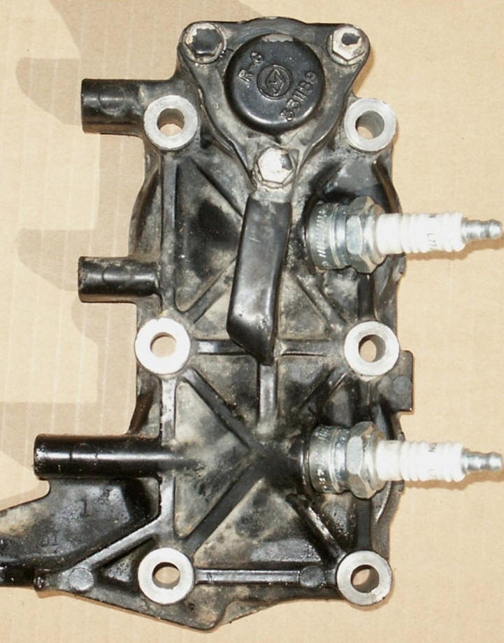
Removing the Head : There was a change in the head and the thermostat cover with scallops cut (as shown below in center) to allow better access to both spark plugs in about 1977, with the thermostat gasket also being changed at this time. The head can be removed without removal of the powerhead.
You will need to unbolt the coils and powerpack, if so equipped, move them out of the way. The you will have to remove the vertical mounting bolt that secures the head's mounting arm on the port side to the lower pan cowling thru the rubber mount. Then remove the 6 head bolts. You should now be able to remove the head. However it may be stuck because of the head gasket. Usually you can rap it sideways with a plastic mallet or find some place to pry it away from the block with a large screwdriver.
Once the head is off, you can inspect the water jacket for corrosion / blockage, also remove the thermostat and check it. This gives you a chance to also inspect the tops of the pistons for any irregularities and/or the cylinder walls for evidence of galling.
Look at the head gasket. Is there any sign of a non sealing surface between the head and the block. The head may be warped and need to be resurfaced. This can be done with a good file, but better by using a medium valve grinding compound on a old glass window. Place the compound on the glass, then place the head on top, apply downward pressure on the head, move it around on the glass with the compound, doing figure eights, lapping it enough to take off any high spots.
You will need to scrape any residue off both the head and the mating surface of the block before reassembly. It is recommended to not try to reuse the head gasket.
When the factory assembled this motor the latch was in place before the powerhead was bolted on. When you are working just on the head, you need to place the lower head bolts into the head before you slide it in place or you will not be able to get then because of lack of clearance.
| The head showing the thermostat cover for motors from 1974 to 1976 | The head showing the thermostat cover for motors from 1977 to 1986, note the scalloped cut outs for the plugs | The head
for motors from 1987 to 1992 with the thermostat on the top & no water jacket cover |
|
|
|
 |
The later motors, at about mid 1987 have a different head as mentioned above. The water jacket that the thermostat is housed in, was changed to place the thermostat on the upper rear, making it a lot easier to access the thermostat. This thermostat is all together different, in that is is encapsulated inside a plastic unit. And the thermostat plate gasket is simply a neoprene O-Ring. When re-installing the thermostat on these, it might be wise to add some anti-seize to the cover threads.
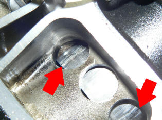
Removing the Bypass Cover : The next step of inspection would be to remove the bypass cover on the LH (port) side of the motor facing forward. If your motor has a electric starter, this cover is also the starter mounting base. With this cover off, you can see into the side of the powerhead where you can see the sides of parts of the piston and the rings, which will give you another clue as to what may be wrong. Is there any black carbon on the sides of the piston, which would indicate that the rings are indeed stuck allowing a blow-by. Check to see if the rings are stuck in the ring grooves, or is the piston grooves worn enough so that the rings wobble in the groove?
| Bypass cover removed showing pistons thru holes, note top piston evidence of scoring & pits ON piston | Bypass cover removed showing scored pistons & very likely cylinders also, indicating possible seized or broken rings |
|
|
 |
| Note rust, especially for the bottom cylinder. This motor had blown head gasket on lower cylinder | This motor was smoking excessively, loss of power & using lots of gas |
Does it Really Need to be Rebuilt ? What is wrong ? If you have done the 2 previous steps, you should have some indication as to what condition your motor is in.
If there appears a problem, this problem should be diagnosed before jumping into a rebuild. Why does it not start/run right? What is the compression? Is there any spark? What about the fuel system? Does it rattle (piston wear) when running slow? All these need to be checked out and sometimes just the little things are the culprit. If the spark plugs are fouling a lot, are they the right ones, and is the fuel mixture right, what about possible debris in the carburetor or are it's adjustments right? If any of the above CAN NOT be remedied, then a rebuild, or at least a re-ring with new seals may be considered.
But will it be cost effective, even if you do the repairs yourself? Of course if there happens to be a blown piston, then you have no choice than to rebuild, other than scrap the motor. Another option is to watch e-Bay. However in the past recent years, these parts appear to be drying up somewhat. Occasionally you will find supposedly running power-heads for a decent price off motors that had a bad lower unit. You will be amazed at the demand for these old parts and with the pre 93's being made for 18 years, there are lots of them out there being parted out, also others in search of parts. But be careful as what the seller advertises, as most do not know what they have or what years will interchange. Do not buy it unless the seller can identify the year AND that it may be compatible with yours.
My repair time to re-ring a motor is 2 hours to remove the powerhead from the mid-section, 2 more hours to tear the powerhead apart, hone the cylinders and replace the parts, plus another 2 hours to re-assemble everything. Then unless I run into an unexpected situation, it usually takes another half hour or so to get it running right. So you can see a possible repair cost near $500 just for labor if it is taken to a marine mechanic who gets $75 an hour. FAST FORWARD, prices have went up even to $125 + an hour.
In any case if there is any question as to condition of a motor, it is a good idea to pull the head and the LH side bypass cover. With both of these off, you can at least take a peek inside for possible clues as to the condition of your motor. This will give you some idea as to what direction you need to go if repairs are needed. If the cylinder is scored and the pistons/rings are scored/damaged it is pretty sure thing you will not get it running with any reliability by just reassembling it.
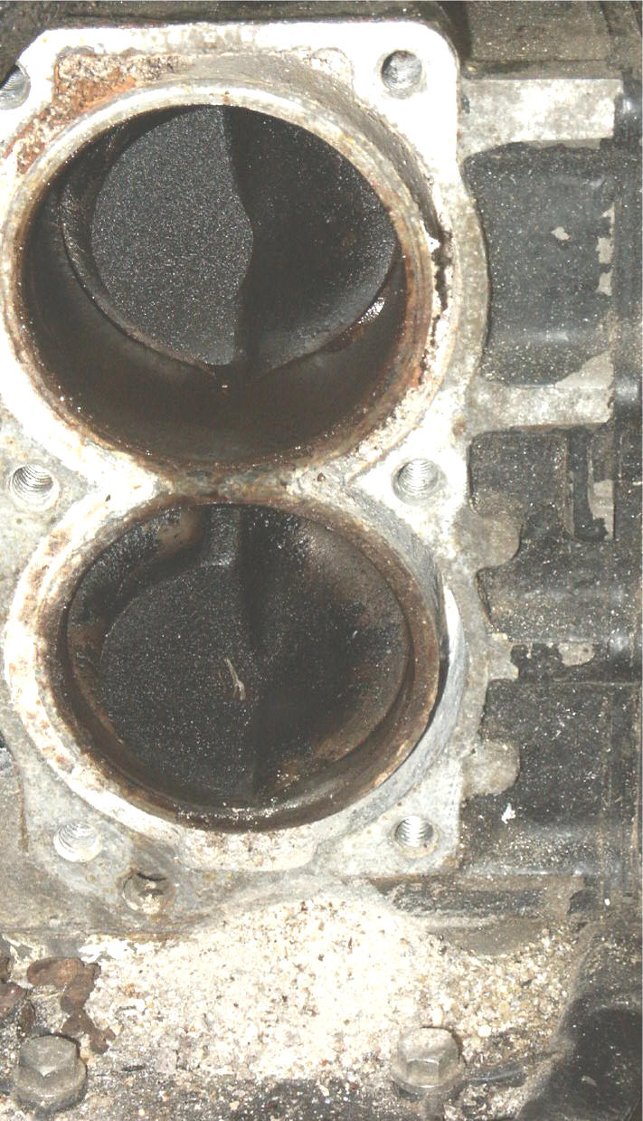
In photo below of a motor that came from Texas, you can see all the salt corrosion in the water jackets between the cylinder walls and the outer block walls. This corrosion was so hard that a hand drill motor and 1/8" drill bit was used to rout out the RH side only of the lower cylinder in this photo. With the accumulation of this corrosion laying at the bottom. The whole LH side water jackets are solid corrosion. The cylinders are rusty, lower ring stuck on #2 piston, compression was better than expected however.
It is hard to understand why this motor was not flushed after usage in saltwater, as it is a 1994 that has a factory flush plug made into the upper top of the water jacket cover and the word "FLUSH" near it. Probably lack of knowledge or just plain LAZINESS. The pile of white dust at the bottom of the photo is dried salt/aluminum that came from the water jacket and only from the RH lower cylinder area.
| The motor below as described above. |
 |
Removal of the Powerhead : If I give the worst case scenario on some of these situations, don't think that it may be normal, only that I am trying to pre-warn you of what MAY happen and give you possibilities of how to proceed from there.
If any of the bolts appear frozen, you might try to eat it up and tap the bolt head with a hammer, this sometimes slightly breaks a bond between the bolt and the plate it holds.
I have found it best to have used margarine buckets or similar plastic dishes to put the screws, bolts or pins and washers into. If you have 3 or 4 of these, you can then place the parts into different ones pertaining to the different parts of the motor. Then remove the shift lever cotter pin and cross pin, allowing the clevis to be disconnected from the shift lever. Next, take the fuel line loose from the fuel pump.
Another thing you may need to do is to cut the kill switch wire that goes into the rubber coupler. Later units have a bullet type quick connector on this wire. The kill switch ground wire (usually a yellow with black spiral stripe, while the older ones may be just two black ones) can be unbolted from the powerhead.
Remove the lower unit, water pump and driveshaft. If this lower unit will not come off, see the paragraph relating to this below the photo.
If after you have all the bolts loose if it will not budge, what is holding is probably the gasket between the powerhead and the midsection. This gasket has it’s own self adhesive on it to be sure it seals, sometimes better than needed.
One of the manuals say “that after a few years the powerhead could become stuck to the exhaust housing and very difficult to remove, we will assume that it came away easily and move on”. Not much help in my book, so read on.
I have had a couple that did not want to come apart. One, I used a heavy rubber or plastic mallet and judiciously hit the high sides of the block trying to move it sideways. The other I ground down a large screwdriver to near a knife edge, lifted away the foam rubber grommet that is showing that covers the front juncture of the powerhead/lower unit/ lower pan. Drive this screwdriver point INTO the gasket. Do it again on the other side. You might be able to now use another large screwdriver on one side and try to pry down with both, pushing the powerhead up and apart. You should be able to break the bond this way, once it starts you may be able to work around to the rear. When you get it off, you may have to file off any burrs you have created.
The round headed Phillips screws showing on the upper part of the exhaust housing only hold the upper motor mounts in, so removing them will do you no good here.
| This is about the only location where you can apply external leverage if the gasket is stuck tight to the 2 surfaces. |
|
|
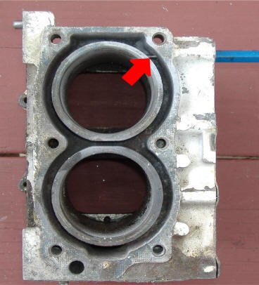
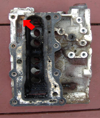
Hole in Water Jacket ? : When you get it apart and happen to be cleaning the water jacket around the cylinder walls and happen to find a 1/8" hole near the upper part of the block on the starboard side, don't panic. You will see as shown in the photo below on the left, a pin punch poked through this hole from the outer water jacket side and into the water jacket surrounding the cylinder wall. Then observe the matching hole in the water jacket passageway under the side water jacket of the right hand photo. This is a factory hole.
It is there apparently to eliminate any chance of a air pocket in the upper part of the block, which could create a hot spot and be detrimental to the motor. Also if the thermostat happened to be plugged with debris or become stuck closed, this would supply a limited amount of water to the block behind the thermostat.
| Notice the pin punch protruding through & into the water jacket around the upper cylinder. | Here you can see the other end of the hole on the left |
 |
 |
Can Not Remove the Lower Unit From the Exhaust Housing :
If after you remove the
above shifting rod coupler bolt and
you CAN NOT get the
driveshaft to come loose from the crankshaft splines up inside the housing,
your only way to separate the exhaust housing from the lower unit is to
drive a couple of wooden wedges (or timber fallers plastic wedges) in between the two, forcing them apart.
In the process, the driveshaft with the water pump impeller key will be
forced out through the top of the plastic water pump housing, usually
breaking the top of the pump housing. You might luck out in that it
only ruins the water pump's top seal.
It just about has to come off, as there is not enough
room to assemble everything off the bottom and still tighten the water pump
housing screws. The only other alternative is to pull the powerhead
to get to it. But that will probably be harder to accomplish the
goal.
Once the driveshaft key has
been pulled through the water pump, the driveshaft will now just slide out
of the splines of the gears in the lower unit and out of water pump.
If it broke the plastic housing, you may need a new housing, or at least
probably a new seal #0318972.
Only thing to remember is if
you now tip the lower unit, gear oil will leak (RUN) out the hole where the
driveshaft was.
To pull the driveshaft from the stuck section in the
crankshaft, you
may have to tip it upside down and pour penetrating oil in. If
you just poured oil in, it would have to be over 2 1/2" inside before it
would get up over the raised boss that the shaft goes into. A better
way would be to again tip it up, but at a slight angle, pour a slight
amount of penetrating oil ONTO the shaft, allowing the oil to run down the
shaft so it would be able to go up inside the raised boss the shaft is in
on the lower part of the powerhead. Pour enough in so that you are
sure it may be getting to the spline. Let this set for a few days.
BTW one of the best penetrating oils is a 50/50 mix of Automatic
Transmission Fluid and Acetone. A second choice would be
hydraulic brake fluid.
Then you can clamp a Vise Grip plier onto
the shaft (at a location where no seal or impeller will be). Using a
big hammer, pound on this Vise Grip trying to drive it out of the splines
in the crankshaft. You might mark it somewhere so you would have an
idea if it starts to move. Try to pound it out, let it set again.
Pound on the lower end, trying to at least move it a tad bit. Pound
on the pliers again. You do not really care if it mars the shaft IF
it is in a location where no seals are located as you can file that down
later .
You
may have to beat on it repeatedly over a few days and all the while trying
to rap it also sideways to loosen the rusted in connection. When you
put it back be sure to grease the splines with waterproof (boat trailer
bearing) grease.
You will get it off, but it may take a while and then will have to file off the marks on the shaft as the water pump housing and impeller has to slide over this upper section of the shaft.
|
Here, showing the 9.9 powerhead removed from the exhaust housing for clearer understanding, with the driveshaft as it would be when stuck & upside down |
|
|
| The extension's lower end positioned just above it's mating hole when assembled shown on a post 93 model |
|
|
If
the powerhead does come loose but only rotates slightly, you can not
rotate it sideways very far, as there is the inner exhaust tube and the water pump
outlet pipe both attached into the bottom of the powerhead which keeps it from
rotating.
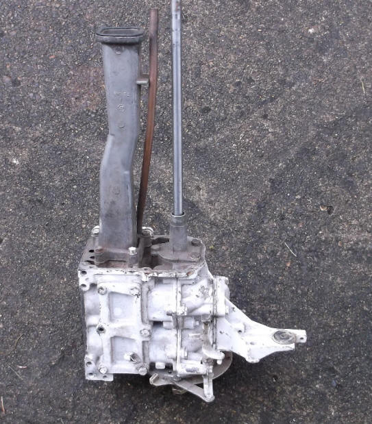
Once the powerhead is loose and all the parts are off, pull it up and off. There will be an squareish exhaust tube about 1 1/2" across if the motor is the older 9.9. If a 15 hp after about 1987 there will be a rounded exhaust tube. Also a ½” copper water supply tube will be bolted onto the bottom part of the powerhead. Unbolt this block and remove the attached parts.
|
9.9 Powerhead with exhaust tube & water supply tube, note the squareness of the exhaust tube |
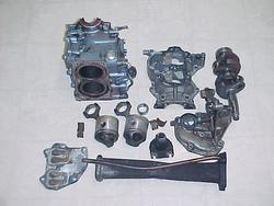
A pre-93, 9.9 Powerhead disassembled |
|
|
|
Disassemble the Powerhead : First you will have to remove the 4 outer screw that hold the armature plate with the charge coil and timing sensor coil. Next remove the 4 screws that hold the retainer plate. Now you can remove the crankcase head, which is a aluminum plate with a circular tapered tube that us held on by 3 bolts to the underside of the powerhead, which the driveshaft does up into connecting it to the powerhead. Remove the head. Next remove the intake manifold, the reed valve plate and the bolts under it for the front half of the powerhead.
Now the powerhead should come apart at the center or crankshaft area. It will have an alignment dowel on one side, which may have to be tapped out. If the two halves do not want to come apart, readily, then with a plastic mallet, tap the crankshaft forward or rearward.
Once you have it apart, you now can get to the connecting rod bearing caps. Loosen the Allen head cap bolts , take the bearing caps off. There should be a mark on these so that they have to go back the same way they came off. If not, it is best to file 1 mark on one side of the top rod, either right or left on both the cap and the rod so you know where it goes back. Do the same only file 2 marks on the bottom cap and rod. When you take the roller bearings and cages out, place them, or mark them so they will go back on the same rod they came off of.
On this motor the rod bearings are also the same as the center main caged needle bearing from 1974 up until 1983. The bottom main bearings are regular ball bearing type bearing which is pressed onto the crankshaft. In 1984 the center main bearing was changed to individual needles. This center main bearing is a split outer shell with needles between it and the crankshaft. Be careful when you remove this bearing from the post 84s and count the needles (there are 22) as if you loose one, this bearing unit is No Longer Available from the factory. This loose needle center main bearing was used from 1984 through 2007.
The top main bearing is a caged roller unit. Regular
automotive type seals are used top and bottom.
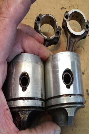
The
crankshaft journals are the same. The pistons are the same bore size,
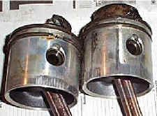
but the difference is the larger wrist pin size, as seen in the photo below, with encapsulated bearing
sets vs loose needle bearings, and one oil hole vs 3 holes in the newer rod
cap.
|
Here the early piston on the left |
|
|
The wrist pin bearings were changed from a captivated
capsule of needle bearings from 1974 to 1983 to individual loose needles in
19814 The wrist pin number is different and the word is the wrist
pin was enlarged, probably to fit the new bearings. 1975-1983
Wrist Pin #0318672 encapsulated bearing sets, 1984-1992 Wrist Pin #0325296
loose needle bearings
These later wrist pin bearings consisted of 22 needles. Trying to install them can be challenging UNLESS you cut off a old wrist pin or make a slave pin the same diameter as the old one and the length as the rod. However it may be best to grind a slight taper on one end of this pin for easier alignment later. Grease these needles, insert them around your slave pin, align the rod in to the piston and push it out with the new wrist pin, using your slight tapered end of the slave to self align. Push the new wrist pin in, pushing the slave out while captivating the loose needles inside. There are also end washers and snap retainer rings that hold thing into the piston.
The rings used are 2 per piston, with the top one tapered from the outside upward and inward. Before removal of the old rings, check to see that some may be stuck in the piston ring groove. If so break one of the rings and use it as a groove cleaner to remove any carbon. We are making an assumption here that with the motor this far torn down that you are going to re-ring it, so you need to hone the cylinder walls enough to score them, helping the new rings to seat properly. If you do not have a hone, then it is suggested that you use emery cloth of about 80 grit, sand the cylinders in a circular motion to break the glaze and give the new rings something to help seat them in.
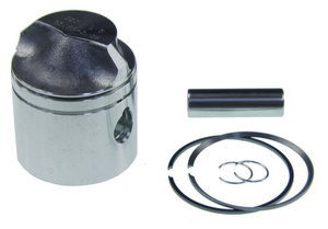
These 2 cylinder engines use a 2.188" standard bore piston which fits both the 9.9 and 15Hp from 1974 to 1992. However if you order new piston assemblies, the 1974 to 1983 uses a different wristpin than the later 1981 to 1992 motors as mentioned above.
| Piston
assembly including rings, wrist pin & retainer rings |
 |
Remove all the old gaskets, clean the areas where the gaskets were. It is suggested that you do not try to scrimp on costs here by trying to reuse the old gaskets. For one, most all of them, other than possibly the head gasket will not be salvageable, and for the price of a couple of dollars each it is best to replace them because in this manner you can get the corrosion cleaned out of the water jacket passages to be assured that you have done a good job. What you can not see under a gasket may well come back to bite you after you get it all back together. Check for any carbon buildup on the pistons and head remove it by wire brushing them.
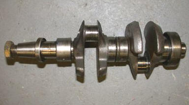
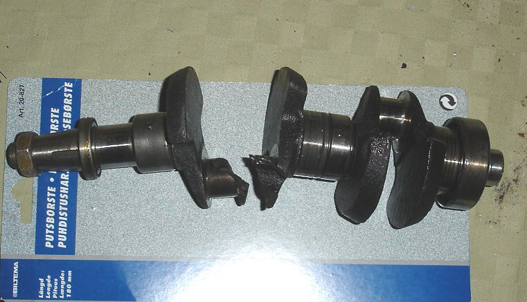
Broken Crankshaft
| Broken crankshaft |
 |
Reassemble the Powerhead : Before you reinstall the rings, it is best to reinstall the rod caps on their rods with the pre-marked sides together, check for internal concentricity. Run your finger nail around inside where the 2 join. Is there a catch indicating a miss-match, tap the cap until it does match. Tighten the cap down to almost completely tight and check again. If you are satisfied that it is true, then check the outside mating edges. If they are off, file them true. What you are trying to do here is assure that the insides are true and then match the outsides. Once you have these assembled on the crankshaft, you can not really tell if the insides are true because you can only see the outsides. The reason they may not match even though they came off together, is that possibly they may have gotten squished on the initial assembly. Here you are just going the extra mile to assure that your repair job is 100%.
Check the new rings into the respective cylinders to ensure that there is sufficient end gap so that when they get hot when the motor is running that when they expand that they brake or score the cylinder walls. If they fit the specs, then install them on the pistons. The pistons will usually have a small pin in the ring grooves. The ring will have the ends thinner to match the pin, which keeps the ring from rotating and requiring the proper positioning of the ring, later having the end get at one of the openings of the cylinder port, thereby giving a chance for it to break or score the cylinder wall. Lightly oil the pistons, insert into the block using a ring compressor, with the rod pointing forward to allow the piston to be seated below the cylinder opening.
If the rings are allowing blowby, you could get a low crankcase vacuum that will not suck the fuel in through the carburetor properly and that will disrupt the pressurization needed to push fuel thru the intake ports into the combustion chamber. On these 2 cylinder motors the crankcase is separated for each cylinder, if you do a teardown, you might consider replacing the center main bearing as well as that also works as a seal between the 2 cylinder crank cases. This center main bearing outer case is split in two pieces so it can be assembled around the crankshaft. It appears the be a crack on both sides. Don't ask how they do that.
Install the crankshaft bearings, place the crankshaft in place on the block, assemble the rod bearings, making note of the previous alignment markings. You may find that an extra roller bearing will be included than actually needed. I was sure I replaced all of them in one rod, but when I found an extra one the next day, I tore the whole thing apart again just to be sure. Place the rod bearings in the rod, install the rod cap, lightly tighten the rod bolts. At about 98% tight, run your fingernail on the outside edges of the rod/cap juncture to feel if they are aligned, if not tap the cap, check again. These caps need to be 100% true on the inside so the rod bearings have a smooth surface to ride on.
| In case you forgot which way the pistons came out |
|
|
As for tightening torque, my personal opinion if you use proper sized wrenches, the torques is really relevant as the rod bolts are Allen head and you can only put so much on the bolt using a standard Allen wrench. If you use a 3/8" medium handle ratchet for the rest it works out about the same. However here is what the service manual.
Check the mating surfaces of both halves of the block, file any burrs if necessary. Place the aluminum mating gasket cement on the two halves, assemble them. Replace all the bolts holding the two halves together, being sure to remember the one under the intake manifold.
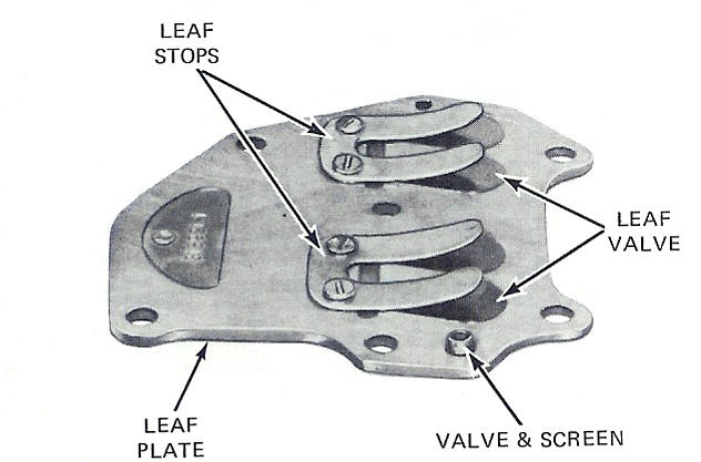
Leaf Valves & Plate :
Install
the seals and the crankcase head. Check out the reed valve unit,
(factory nomenclature they are called leaf valves so you will see either names
used) be sure that these valves are not rusty or bent and lay flat against the
plate. Replace this unit and the other covers
etc. It is not required to use regular gasket sealer as these
gaskets adhere quite well. Be sure that you have the right manifold
gaskets in the proper place. IF you happen to place the front gasket on
the rear of the reed valve plate, this gasket has a smaller opening for the
valves. It will hold the reed valves closed and you WILL NOT get the engine
to run more than even a pop or two.
Here is something that is usually overlooked. If the leaf valve
plate is stuck to the block by the gasket and if you try to pry it off with a
screwdriver, you may well bend it or at least upset a but in the aluminum
plate. You will need to be sure the plate is flat, otherwise the leaf valves
will not close when the engine is back together and any slight leakage will be
detrimental. Do not rely on the
manifold to straighten this plate when bolted down. File off any burrs
you created. Check the plate for straightness, if bent use a large heavy
metal plate, after removing the leaf valves and stops, try to straighten it
with a plastic mallet. When you get it as close as possible, then
get a piece of glass, course valve grinding compound and lap the plate so it is
flat at least where the leafs lay. Clean the compound off,
reinstall the leaf valves, see that they lay tight to the plate. The
manual says do not try to bend them, but I see no reason that you could not if
you do so only so that they JUST close when in the assembly condition.
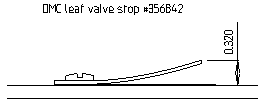
The manual also does not say anything about the height of the valve stops.
I have taken this dimension from the top of the stop to the plate off existing
operating motors as shown below.
If these valves are not in correct contact, by not being installed right, or the plate bent, or not tight under the manifold by burrs, the motor will not run right, as idle, burn lots of fuel and leave oily residue on the water.
| Leaf valve plate assembly | A side view of the leaf valve stop |
 |
 |
Frustration on a Rebuilt Block : I had purchased a used powerhead off eBay, that was supposed to have been rebuilt. It had evidence of being apart, or at least reassembled, as there was red gasket sealant on many of the gaskets on the block. When I finally got around to installing it on a motor, and trying to start it, TOTALLY NOTHING not even a pop as to trying to fire. Compression was acceptable, spark was good, carburetor cleaned, I even tried starting fluid and a 1/2" heavy duty drill motor attached to the flywheel nut. Only got a slight cough once. Now the problem arose in that I had to use an impact wrench to remove the flywheel nut.
Doing all the right diagnosis, and sleeping on it for some time, I finally concluded that maybe this so called mechanic had installed the manifold and reed plate gaskets on the wrong side of the reed plate. If this was the case, the wrong (smaller opening) gasket would be holding the reeds closed, not allowing it to suck in any fuel.
So the lower unit was removed and the powerhead. The lower unit was so that the driveshaft could be later aligned by installing the lower unit. It would have been rather hard align the water outlet tube from the opposite end where I could not even see the water pump grommet.
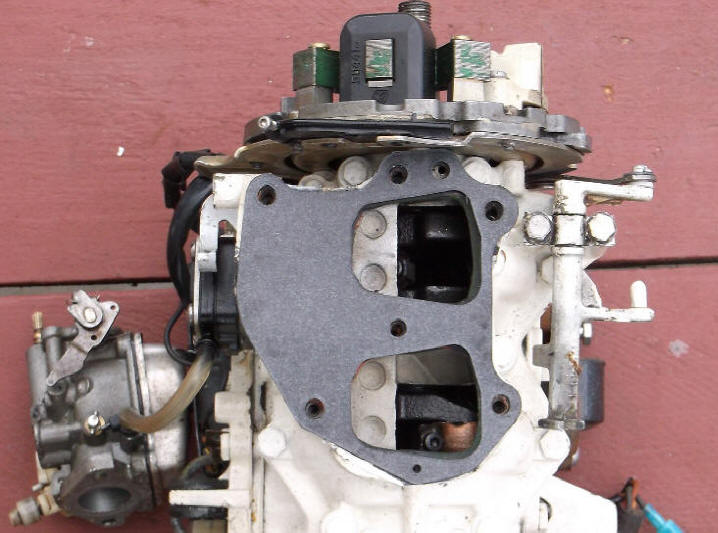
I found the problem, not quite what I had expected, but the same issue. The reed plate gasket was homemade, with a considerable amount of excess material in the wrong places. In the photo below, you can see the homemade gasket UNDER the gray new factory gasket. On the right-hand side you will notice enough extra material protruding inward enough to totally block any movement of the top two and the bottom reeds. Three out of four reeds blocked. It could not even suck in any of my starting fluid. There is not a lot of extra clearance on the moving ends of the reeds.
Maybe that is why he sold it after his rebuild when he could not start it. So just because some seller said it is a rebuilt unit, WELL -- NOT ALWAYS. And this same motor still would not fire. After a total tear down, also found that the motor has been seized at one time, probably because of a leaky head-gasket as evidence was there in the cylinders and on the pistons that at one time there was RUST inside the cylinders. Nothing bad on the bearings however. This "mechanic" apparently had just re-ringed the motor, however never honed the scoring or the pits out. Just another item to add to my ongoing "Ramblings".
| Here the new gasket is laying over the homemade gasket, notice the excess material of the darker gasket at the ends of top two & the side of the bottom reed port |
 |
Bad Block : Occasionally you may run into a bad block for one reason or the other. It could be a broken ring that scored a cylinder wall badly, it is not practical anymore to rebore these It could also be a very worn and oversized cylinder holes, again not practical to rebore. It could even be a blown piston with a hole out the side that can not be welded or twisted off bolts that in trying to remove, the repair went south. Most of these blocks are pretty much interchangeable if within the the close years of manufacture.
Converting an early points type ignition block to a electronic ignition unit can be done, IF ALL the electronics, like the timing base, flywheel, coils, and power-pack are also changed. The head will have to have a bracket made to secure the power-pack onto. However this conversion is not really worth it unless you happen to have two motors (one a donor) that you can swap parts from / or to.
I have recently found one combination that will work IF observations and modifications are looked at closely. I had a 1987 15hp that had a badly worn set of cylinders. I also had in my pile of parts, a block off a 1982 that had been recovered from a watery grave where the cylinders were slightly rusted. The water outlet and exhaust parts were a match, (not so on some earlier blocks in the pile). I honed it out, and surprisingly the cylinders came out good enough to warrant the change. This motor I was trying to repair had the newer cable throttle system. Upon reassembly I was having problems getting the timing base to rotate the full requirement. Plus the recoil starter could not be bolted down tightly without binding, the neutral safety anti-start ratchet would not function.
What I found was that, I had utilized the same vertical control shaft plastic shaft clamps that came off the 87. The older motors using the gear type linkage used a sheet metal clamp where the new plastic clamps on the old block pushed this shaft 1/4" forward when using the old block. I also found that the base for this clamp was changed on the 87 by machining it at an angle as compared to just let the boss extend to the rear. This was for clearance for the new type cable connector to the timing plate.
There appears to be about 3 variations in these 74 - 92 blocks. Note the differences in the early 74 style on the left with the later 87 block water outlet passage indicated by the blue arrows. I suspect this would not be critical as both use the same gasket which has a hole directing the water out, but that it may create a "Hot Spot". JB Weld and a Dremel tool would possibly fix this situation if you think it need be the same, but this is the final water passage, and the gasket is the same, so no real deal.
| Old block (probably a 77ish) shown upside down with full boss for vertical shaft pivot | Newer block (87+) shown upside down & with part of the boss beveled off for throttle arm clearance |
|
|
|
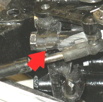
Also note on this photo below on left, that the older metal clamp had to replace the newer plastic clamps, as indicated below by the red arrows.
| Here the vertical shaft new style clamp needs to be replaced as not enough room to fit recoil starter | Here the old style clamp has been installed on the newer parts, giving room for starter. Also notice the modified block boss to fit new type throttle cable system |
 |
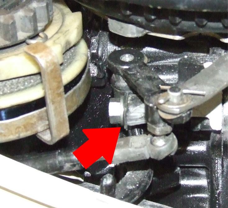 |
The red arrow below shows the metal removed for clearance of the ball and socket assembly on the end of the cable attached to the timing plate.
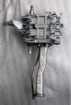
Exhaust Tubes : Prior to 1981 OMC Both the 9.9 and the 15 hp exhaust tubes were the same, after that the 15hp was different. In the pictures shown below, the 9.9 and early 15 hp is on the Left. It's tube is a rectangular unit, while the later 15 hp unit is basically a somewhat tuned 2 stroke exhaust. They both utilize the same water supply tube, (not shown) but that goes in the front or lower RH holes of the RH pictures. The older 9.9 housing being longer, mounts against and is sealed by a rubber ring the inner section of the lower unit. The 15 hp pipe stops short, why I can't imagine. The short copper tube on the rear of the 15 hp housing is for the warm, used water to exit the motor at a lower location apparently since the whole inner housing is now somewhat pressurized when being used and the motor lower unit buried in water.
Then in about 1987 another exhaust tube was brought out, or so the parts list show, however I have never actually seen one. This mystical one is a short rectangular unit, is used for both the 9.9 and the 15 hp motors. My reasoning for the 87 date is that the 86 parts list still shows the old housings, the 1990 list has the newer one. This motor underwent many changes in 87 as to thermostat, fuel pump, twist grip throttle, etc. but my 87 15 hp uses the same as in the right of the LH photo below.
| Old 9.9 & 15 hp exhaust pipes on LH, with new combo 9.9/15 housing on RH side | Same 9.9 & 15 hp exhaust pipes, top view |
|
|
|
For an explanation of possible water tube grommets deteriorating where they attach to these exhaust tubes, possibly causing water blockage CLICK HERE for a link to my water circulation problems article.
Stripped Spark Plug Threads : Occasionally you may encounter this situation. If it is a 1974 - 1992 motor, you can probably find a used head on on e-Bay. One caution here is the 74-76 heads will fit the 77-92 motors but will not have the mounting lugs/holes for the powerpack. For the post 93 heads since there are less of them out there, so finding a used one will be about be impossible.
The method of repairing a stripped thread is to drill out the old threads, install a new threaded bushing using the Heli-Coil method. The regular Heli-Coil unit uses a tap that consists of a dual threaded tap, one threading into the old threads and behind that are flutes that cut and re-tap to oversize all at the same time. The one problem with this method is that if you can not get the pilot tap to enter the damaged threads straight, you are in trouble. Hence the photo below.
A Heli-Coil kit for this size thread is $40.00 so unless you may need to use it on other motors, it might be best to take the head to a automotive machine shop. If you plan on doing it yourself, no real problem, just follow the directions. For the 74-92 motors where the plugs are at a single angle with the head, it is not a real problem. But you have to get it right the first time, if it gets started cross-threaded, when finished the spark plug gasket will not seat properly against the head because on these Heli-Coil taps, the pilot needs to thread into the existing threaded hole, so you need enough good threads for the tap to follow. This is not normally the case after the old threads are stripped.
However if you happen to be working on a post 93 motor where the spark plugs set at a compound angle, (both to the side and upward) it is hard to be sure that the tap is in proper alignment. This is also why it is a challenge to even start the spark plug correctly because of the dual angles and the hole is below the top of the lower cowling making for visual observation hard.
Shown below is a photo of a compound vise set up in a vertical milling machine so the tap goes in at the same angle that the original spark plug threads. This is not really the facilities that the average shade tree mechanic has available to him. In setting this up, the tap's pilot threads were screwed into the good hole, the compound vise rotated in two angled directions until the tap was level and perpendicular to the mill's table, then the table was moved to align the quill to the bad hole. Next the tap was just started in the bad hole with a quill center point into the small center hole of the tap, leveled in all directions by moving the table as required. Once the tap was leveled to the hole, pressure was exerted by the quill while at the same time the tap was turned inward with a wrench, cutting oversize threads so the Heli-Coil insert could be inserted.
| A fixture set up for proper alignment to re-tap a spark plug thread in a 1994 head |
|
|
Parts & Gaskets Most Likely Needed : If the motor is in need of repair, the most common problem will probably be the rings need replacing. The rod and main bearings will usually good. Seals should probably be replaced whenever the unit is torn apart. And a new gasket set is probably in order. If you order a gasket set, check for the components, as if it is an OMC set, usually the bottom crankshaft seal comes with the set. If it is an aftermarket set the seal does not come with the set. A gasket set will also include, carburetor to manifold gasket, fuel pump base plate gasket and fuel filter gasket among others. The headgasket for the 74-92 motors are different than the post 93 series because of the larger piston. The earlier gasket will fit, but the first time you pull the starter rope, the top of the pistons will hit the edges of the gasket ruining it.
The likelihood of of salvaging the manifold, sideplate and bypass cover gaskets is very minimal, over 1/2 the time. And the headaches involved by reassembling the motor and getting a badly running engine that needs to be torn down to just replace these gaskets are something that you do not need, especially since the cost of these simple gaskets are minimal. So if at all possible try to use new gaskets especially on the reed valve plate and the intake manifold.
I have seen the head gasket come off clean enough that it can be reused if applying a light coating of a good gasket cement. This is not recommended, unless the head is true and no visible problems. However the increase in the price of this gasket has brought many to try the cement trick.
You will also need a sealer designed to seal the two halves of the block together that does not utilize a gasket, but only the two mating aluminum parts. About the only time you will need some gasket sealer is if you are trying to reuse an old head gasket. It is however best to wait until you have it all disassembled before you order what you think you may need.
Repaint
Before Final Reassembly :
I have found with the OMC paint, do not try to do thick coverage or it MAY wrinkle. Do many thin coats. In a repaint job from years before that had been painted with Krylon, it did not adhere to the original paint job well and required a complete stripping before the OMC repaint, in the long run, OMC paint may be the best for the exposed parts of the motor.
I am trying a automotive spray wax that goes on after the motor is washed, then wiped dry. Hopefully this will be just enough to help preserve it and keep any oily residue from the exhaust to stain it.
The 1974
Johnson OD green color was changed to white in 1977.
If you plan on replacing the decals, you will probably not be
able to find any OMC originals available earlier than about 1996. Price
is about $50 for these original replacements. If
you purchase these newer decals, you will have to cut them to fit, as the newer side decals sets lower than you might think. This
is because the motors have a upper cowling that the seam is more horizontal instead
of at an angle on the pre 93's. This changes the position of the decals if used on an older cowling. You
will have to trim some off the front bottom at an angle of these side decals to get
the lettering horizontally positioned. And you will also have to trim the
bottom rear decal to be somewhat close to a decent position. Lay them out, tape them on the cowling before you
install them. You will not get a decal for the front where the
control knobs are on these newer decals as there are none used on these later
models.
There has recently became available on e-Bay aftermarket vinyl decals that are generic for this series of motors at a price of about $13.00 + a set. These generic ones are quite good, a close coloration to the originals, but do not match any specific year, have the "Sea Horse" and appear to be laser cut. They appear to be made for many Johnson and Evinrude motors from 6 to 90hp. See the photo below. The lady supplying these die laser decals has recently expanded her line, but with a price increase for the larger models.
| Aftermarket decals on an 1985 |
|
|
When installing any of these, it is best to lightly pencil mark the cowling with the top and front locations of the edges of the decal. These will be VERY sticky, so BE SURE where you want it to do. When you peel off the backing, start on one corner, but just let it lightly stick, if it appears correct, allow it to lay it in a rolling motion, by peeling more of the backing off. You will be trying to get the top parallel to the top edge of the cowling, with the rest laying down while NOT allowing any air bubbles to get under it. IF you are lucky you MAY be able to let one end lightly lay in position, then if the rest appears to lay OK, roll it with your hand working out any air bubbles and pull the first up, re-setting it, rolling it back forward again without any bubbles. If you do get a few bubbles under the decal, take a needle and prick the decal, then work the air out the pricked hole.
If you decide to repaint the cowling for the pre 93 motors and the rubber motor seal is OK, you can pry it away from the fiberglass or plastic depending on the year, placing matchsticks between the rubber and the fiberglass to allow for a better paint job to go under the seal. This original rubber seal is stapled onto the fiberglass. If you need to replace the seal (about $40.00) after repainting, to reinstall it instead of trying to staple it, just use a latex adhesive and many old spring type clothes pins until the adhesive dries.
The later motors after about 1987 had the power head, flywheel and prop painted black.
Removal & Replacement of the Motor Upper Thrust Mount 74-92 : OK, let's set the record straight, to do the following repair the power-head HAS to be removed.
With the motor in normal operation the movement between the motor swivel base unit and the actual pivoting part of the motor should be minimal. The upper thrust mounts are a rubber anti-vibration connection between the pivot shaft unit and the swivel/clamp base. If the rubber mounts are broken / unbonded from their attachments there will normally be more forward/aft movement than lateral movement simply because of the way the mounts are made. Usually only the upper mounts go bad and the lower rubber mounts are OK.
These
upper motor mount usually does not require any attention. However I have two
motors that I purchased used, that had been used with a clamp around the
housing that was used for a trolling tie bar to an I/O unit. The problem
was that whoever attached it to the motor put the clamp around the lower
housing AND the driveshaft housing. This put so much pressure on the
rubber mount that over time it disintegrated which left a lot of wobble forward
and
back. This may not be the only reason these upper mounts go bad
however.
These motors use 2, one on each side. Both sides use the same mount as
they are made symmetrical with one is rotated 180 degrees of the other.
In the photo on the left below you can see the thrust mount arm (the horizontal bar). Around it the black ring is what is left of some of the grommet which seals around this arm. This grommet is made as a bellows, which when it goes bad, it deteriorates at the folds in the bellows. In this photo it is obvious that the grommet is bad, allowing unburned oil to be blown out. Many times the motor will be noisier because of the exhaust being blown out there also. Another way you can tell if this mount is bad is if the gap between the exhaust housing and the pivot housing is not even from top to bottom, the mount is bad letting the motor's weight tip the powerhead rearward.
| Bad upper thrust mount & grommets showing housing tilted rearward | Upper thrust mount (lower) attachment screw |
|
|
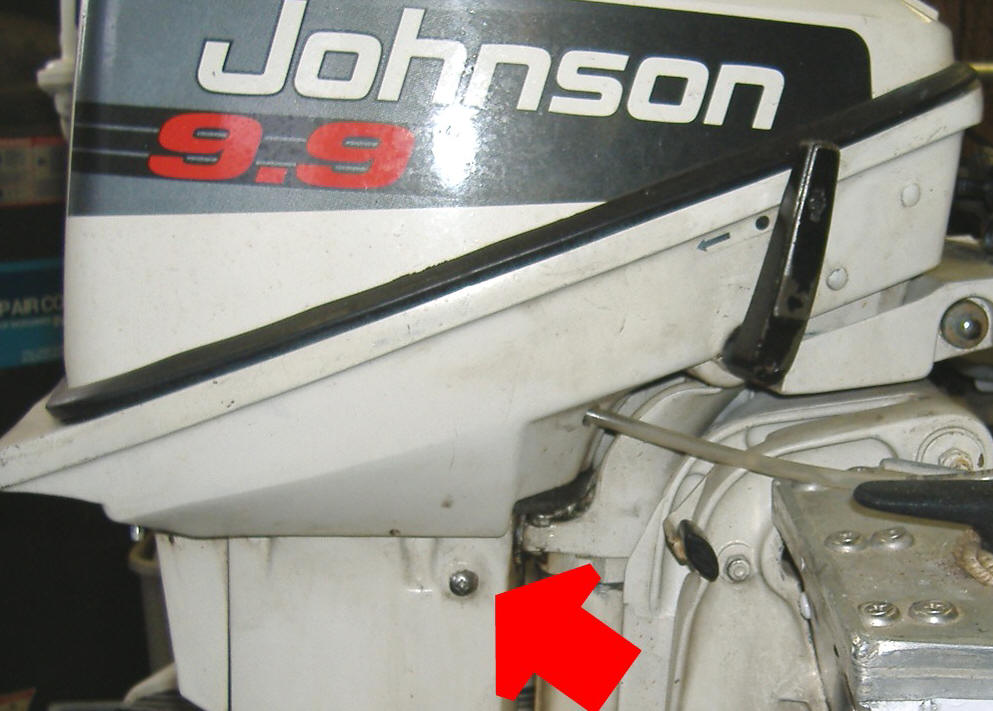 |
There are 2 screws from the outside of the housing, with only one showing until you remove the lower cowling pan and they / (it is shown above) may well be frozen into the internal bracket. They may have to be broken loose by the aid of an impact driver set. When you strip the Phillips heads, you may have to set it up in a sturdy drill press or milling machine and drill the screw head off. All you need is to get thru the head, as the threads are usually loose in the inner bracket, but the screw body is corroded in the exhaust housing. Then you may be able to drive it in to take it apart, then twist out the remaining screw threads. Replace these 4 1/4" screws with stainless, then coat the threads with an anti-corrosion compound.
If, when you are doing a powerhead repair, while the motor is this far torn down it may be best to at least check this rubber mount. This repair requires the complete power head be removed to get to this upper mount. The twisted off or milled off 1/4" bolts shown below are what was left of the above indicated bolts.
My Homemade Replacement Upper Motor Mount : In the photo on the right below is my thrust mount conversion. Since I can not bond the rubber like the original was, I use a tight fitting friction compressed fit to hold it in place. I use the standard motor mount rubber (factory nomenclature "grommet support" #316354) of which there are 3 mounting the powerhead to the base cowling, as shown at the top 2 items, remove the center steel bushing. Now I take it to a standard medium grit stone wheeled grinder and modify the outer edges of the rubber beveled as shown, but not removing any from the center.
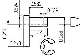
Now I lathe turn a 9/16" aluminum rod down to 3/8", drill a 1/4" hole all the way thru. The placement of the shoulder and the groove are so that the steel bushing that was removed from the motor mount is now centered on the new aluminum, while making the overall length the same as the old center bushing of the original mount. Next I cut a narrow shallow groove for a 3/8" E-Clip so that it encapsulates the rubber at the distance of the old steel bushing.
Shown in the LH photo below are the new rubber mount parts. The rubber can be collapsed on one side into the hole enough so that the rubber can be forced into the mount's original base. The bullet shaped dual diameter piece on the far right is simply a installation tool to be able to push the new bushing into the rubber. Lubricate the rubber center, bushing and the tool with soapy water. Insert the tool into the bushing, push the bushing into the rubber that has been installed, center aligned in the base. The new bushing should be installed so that the forward thrust from the prop pushes away from the E-Clip, or with the shoulder to the front. Now install the E-Clip holding the rubber centered on the bushing.
The damaged old rubber mount is shown at the bottom of the photo for illustration purposes.
|
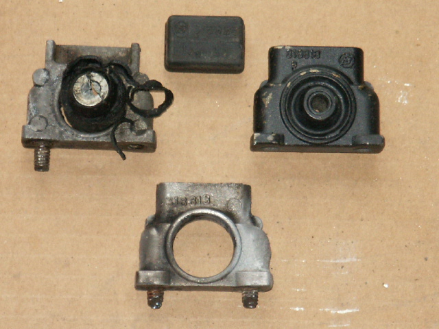
Shown below are the upper thrust mounts for the pre 93 motors. The left & bottom ones show the bonded rubber center torn loose or gone. The one on the right is a new one. The top one is the center rubber mount. |
Here is my alternate thrust mount conversion |
 |
|
| Dimensions of Conversion parts |
 |
Then here
is another DIY version, by using skateboard truck bushings. I
have also heard that Ford shock absorber bushing work great.
| Here you see skateboard truck bushings |
 |
There may be some
confusion here as in the picture below, it shows the 2 mount locations
where the mount assemblies are and a thrust mount in the middle. These
mounts are essentially an aluminum block that is secured into the sides of the
housing by (2) 1/4" screws for each that come in from the outside.
Bonded into these blocks are rubber bushings that have a steel sleeve also
bonded to the hole thru the rubber. Here you may be able to improvise by
taking a thick rubber, freezing it, drilling a hole for the bushing, then
turning the outside down, then glue the rubber to the sleeve with Gorilla
glue. The reason for freezing the rubber is so that you can machine
it. Last Bombardier replacement cost is $38.20 EACH and you need 2.
The
upper thrust mount for motors is a rectangular piece of hard rubber is 1/2" X 21/32" X 1
3/16" in size which is
clamped between a bar inside the exhaust upper housing and two fingers
that protrude rearward thru a set of rubber grommets that seal and
slightly support things. There are four 1/4" Philips headed screws
protruding on each side of the outer upper exhaust housing, (the upper ones are
tucked up under the lower powerhead cowling), that hold the internal
brackets that this mount assembly is attached to.
If the motor was used in salt water a lot, the drilled out studs may well be frozen into the base. To break them free, heat the up the aluminum base with a torch, spray some penetrating oil around the studs as it cools. If the rubber is still intact, you can not use the torch as you will ruin the rubber bond.
There is also a rubber seal or grommet that usually needs to be replaced at the same time as the upper mount. This grommet acts as a seal for some exhaust noise and oily residue from the inner exhaust system. It goes across in front of the housing with bellows thru the housing to then be bound against the mounts on the inside of the housing. In the left picture below, this seal is on the left of the thrust mounts the arrows point to. The seals are of rubber and like a short bellows to allow for flexing. You can see a white space between 2 of the bellows. This white is the 1/4" screws showing, so this particular set of seals also needs replacing.
|
View of upper exhaust housing of the pre 93 motors, from top, note upper rubber motor mounts top & bottom with the thrust mount in the middle. The grommets are the circular black in front of the motor mounts |
Here is shown a post 93 exhaust housing with the new type upper mounting system |
|
|
|
In the above LH photo the 2 bolts that are backed out about an inch, many times you will twist off inside the steering bracket boss when removal is tried. If this happens you will then need to remove the exhaust housing from the steering bracket (as the twisted off threads will now be in the steering bracket boss). This removal is no big deal as you simply remove the lower mount cover, the lower rubber mounting blocks will fall out and the two housings will come apart. This bolt does not need to go into the steering boss as deep as it was originally. I have found that if it does break, it will be at the threads. Just re-tap the hole down to the broken bolt with the next size (5/16") and put in a shorter bolt. You will have to drill the center metal upper mount tube out to accept the 5/16" bolt however.
Redneck Upper Motor Mount Repair : I have devised a somewhat Redneck repair to where you do not even have to disassemble anything. This repair is shown in the photo below using 1/16" sheet metal and drilling the rear end so the upper mount screw can be utilized to attach the exhaust housing. This plate only extends about an inch beyond the front hole and may need to be bent inward on the front a bit to match the contour of the steering housing.
Make the plates and then install them (on both sides) using the existing bolt,
as shown below (if usable) and
mark the forward location while the plate is bolted down. Remove
the plate and drill a 1/4" hole thru it. Replace the plate and
start a location hole in the handle base, thru this front hole, using the 1/4"
drill bit (just drill enough to give a shallow hole) . Then change bits
and drill a .199+- hole all the way thru the rear upper part of the steering
handle column. This hole then needs to be threaded 1/4" x 20 NC.
You now need to countersink this hole in the plate as much as possible as
you will need to use a oval or flat head bolt here to give you enough
clearance so you do not over limit the rotational movement of the motor while
steering. You may have to use a Dremel Tool to reach in and remove
some metal on the steering housing at the bolt head location in order to
facilitate more rotational movement if needed.
Dimensions of the plate
are not critical except the placement of the rear hole so it aligns as tight
to the housing and allows the bolt to be screwed into the inner mount housing
side. The front hole needs to be as far rearward and yet forward enough
so it will not break the housing out later under stress. These plates
need to be made to fit both sides of the motor to get as full a support as
possible.
The problem here is being able to remove the
upper inner motor mount bolts from the housing without breaking them off if the motor was abused, or used near
saltwater. If you do break the bolts, then powerhead removal will
be necessary and removing the broken bolt. However if the upper bolt
breaks off and the lower one comes out, this plate could be lengthened at the
rear to accommodate this lower attachment base.
In the photo below you can see the parts of the top of the upper motor mounts while in their proper location. The two bolt heads seen go through the exhaust housing and into the existing upper mounts, securing them to the housing while there are also one bolt on each side running horizontally and into a finger sized stud from the steering housing unit. Around this stud are rubber bellows that seal any exhaust gasses/oil from leaking out. This Redneck repair will not stop the gas/oil leakage, but may minimize it somewhat and you may be able to clean the old oil up and caulk around the broken bellows.
Just squirting
Silicone in the now oil leaking imbedded bellows will not make any workable
solution. However if you clean
the oil up good and use this strap method, then put Silicone in, that
surely would not be a detriment.
This repair can
be done without disassembly of the motor as compared to the "Proper
Repair".
| Here you can see the external strap securing the steering handle unit to the exhaust housing |
|
|
There are also 2 lower rubber lateral mounts (discussed on the Lower Unit article) that complete the mounting unit. These side mounts normally do not require any replacement, however the front lower mount can get deformed and become a sloppy fit.
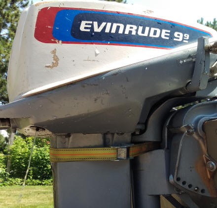
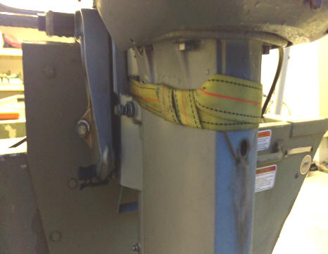
Real Redneck Upper Motor Mount Repair : One of my readers Steve Baia, has bested me on this repair, instead of paying $80 each for these two upper mounts, he simply used an economy ratchet strap to pull the motor's exhaust housing forward and still allow it to pivot. This appears to be quite an economical and effective repair. But an example of not understanding or knowing about this damage before purchasing a used boat/motor off Craig's list. Thank You Steve for sharing. This also appears to be where the long shaft motor was adapted to a 15" transom by adding a riser board on a Jon boat.
|
Side view of upper exhaust housing of the Real Redneck Repair on this 1984 Evinrude |
Here is shown how he took care of the tail end of the strap by tucking it in tightly under the previous end |
|
|
|
Reinstall the Powerhead : Basically reverse order in your re-assembly. As the motors get newer, they start cramming parts in places that were not meant to be, especially when it comes to an electric start model. Here the wires, and hoses have to lay in the exact right position, or things will not be able to fit. Install all the bolt on parts except the manual recoil starter, before you try to assemble the power head unit to the lower cowling and exhaust housing. Be sure that the lower crankshaft seal is in place, the exhaust housing is bolted in place to the bottom of the powerhead. Next, you should be sure the large rubber grommet that acts as a seal between the lower cowling and the exhaust housing is it's proper place on the exhaust housing.
The hard part in installing the powerhead and exhaust tube will be that the 3/8' copper water tube from the powerhead down into the water pump can have a mind of it's own in finding it's way into the guide hole inside the exhaust housing. However I have seen that it may be hard to have the driveshaft crankcase seal unit might not want to slide in between the two upper housing mounts because of swelling of the bellows over these mounts. Here I just smear some wheel bearing grease on the bellows to allow them to slip by.
This tube has to be aligned first, followed by the three motor mounts and timing plate vertical shaft into it's base. The easiest way I found was to get yourself about 2' of 1/4" steel rod. Poke it up thru the front hole in the exhaust housing, and from the top position the powerhead/exhaust tube so the water tube slides OVER this 1/4" rod. This rod now helps you align the tube into the hole, otherwise it is like one blind man leading the other.
Run a new 1/4" neoprene fuel line from the coupler on the LH side, down inside the LH motor mount, around behind and on the right side near where it will go forward, connect to the fuel pump. This fuel line HAS TO GO outside the RH rear motor mount to give clearance to bolt these motor mounts down. If the motor is a manual start, the fuel line will attach to the rotatable fuel filter cover with the hose fitting pointing rearward. If it is a electric start model the filter cover will need to be pointing forward and down as the fuel line needs to be longer to accommodate this move. The reason is the electric start rectifier sits in the location where it interferes with the fuel line. Bolt the 3 motor mount bolts in with the washers both above and below the rubber bushings.
The best way I have found to install the shift linkage rod is to assemble it to the shift lever linkage, install the cotter pin in the pivot pin, then as you slide things together with the rod down in the housing, you can see this rod hitting the grommet near the bottom. There is enough room here to use a screwdriver to reach in, position it so it will go down into the grommet and farther down. You may however have fun aligning the water pump tube so that it goes into it's allocated hole.
It is easier at this point to also be sure that the twist grip mid section throttle gears are aligned and the shaft is in it's proper relationship with the mating holes as indicated by the grooves and mating bumps for their respective locations.
Start the 6 bolts that hold the powerhead to the exhaust housing, once they are started and everything looks like it is OK the snug them tight. Reassemble all the external parts. Replace the lower unit (gear case) as when you would have replaced the water pump impeller.
Break in the Rebuilt Motor : Once started, it might be wise to increase the oil to gas ratio by about double for the first 3-4 hours of run time. The reason for this is that there may be more friction due to tighter bearings and piston rings, which create heat. The extra oil will help keep it from seizing up. Bolt the motor onto the in side of a 55 gallon barrel with water filled high enough to cover the cavitation plate, run it. Do not just run it at an idle, but speed it up to a fast RPM occasionally. This is also a good time to get the carburetor set for it's proper setting at an idle, as you want the motor running at it's best before you get on the water.
To make one of these run barrels, use a 55 gallon steel fuel/oil barrel, cut part of the top out, but leave about 1/3 still attached. Cut back about 5" along the sides of this remaining top. Now bend this 5" section down into the barrel to form a downward lip. This will allow you to rev up the engine for short periods of time while in gear without blowing the water up and out of the barrel, as this baffle diverts the prop water back down into the barrel. In the photo below you will be able to see on the ground beyond the barrel, the top of a galvanized garbage can that is used to keep debris out when not in use.
| Using this rear baffle in the test barrel, a high RPM can be achieved. |
|
|
One thing to check, is that if you leave the barrel set outside from year to year with water in it, you should dump it out occasionally, as any debris in the water can plug up the water intake screens to make you think the water pump is bad when you later run a motor.
Transom Clamp Unit : The transom clampscrews themselves have went thru various changes, from steel or aluminum clamp screws to stainless steel and from aluminum handles to plastic.
The transom adjustment rod was originally a Ell shaped 1/4" rod with a pivoting gravity type end so it would not work it's way out. The later ones did away with this folding latch, but incorporated a plastic clothespin latch into the opposite plastic end.
| Transom adjustment or trim rods with the newer version on top |
|
|
The under parts associated with the shallow water drive reverse locking lever and link, or the motor up lock are pretty much the same for the standard motors. For the motors fitted with the "Reverse Thrust Kit" (as mentioned below) these brackets associated with the shallow water lock, the 2 stamped out parts were welded together. Apparently there is more stress associated with this in extended reverse usage so they were welded together. They however under normal usage, functioned just the same. Shown below is a broken welded unit.
| Here the stronger "reverse thrust kit" style welded version, are broken |
|
|
Reverse Thrust Kit : I have heard about this, but never really knew what it was. Many boaters thought it was heavier or different ratio reverse gears. This however seems impossible to achieve in the existing gearbox.
One day on my browsing e-Bay, I stumbled on the photo below. Now if you go to one of the online marine parts sales (http://www.marineengine.com/) for example, find the year and HP, then on the bottom of the page click onto accessories, then to miscellaneous, you will find "Reverse Thrust Kit" listed. Here it shows the parts in the e-Bay photo below.
In this photo, you can see the shallow water/reverse locking lever and link, being welded together (as evidenced by the black/brown metal discoloration). I assume for more rigidity. The Ell shaped part is listed as a shift stop lock. Not having the lock in my hands, I am not really sure where it goes.
Also in what you can read on the instruction sheet in the photo, in the lower LH of the instructions, it says "Drill 4 holes each here" with a line pointing to the 6 holes in the rear of the lower unit housing. I can understand that in sustained reverse, you may need more water coming into the water pump as the direction of travel has changed in relationship to these existing holes. The thing I don't really understand is of the 6 holes there, 4 are already drilled through to the inside. Maybe they mean to drill out the other 4 blind holes (2 on each side) or better suction to the water pump in reverse.
One thing in this online list, it lists this kit for "longshaft" motors, which I guess that they assume these will be used on heavier/deeper hulled boats requiring more thrust.
| Reverse thrust kit for the 9.9/15 hp OMCs |
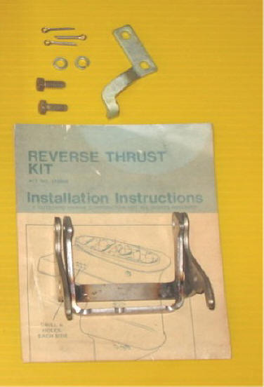 |
OK, You Have to Remove the Stern Tilt Pivot Shaft : IF you ever for what-ever reason have to remove this shaft, IF IT WAS EXPOSED TO SALT WATER, you will have an experience. Do not expect to save it. You might even twist one end off at the nut. I would try penetrating oil, and MORE penetrating oil. Make a steel driver shaft that would fit inside this hollow shaft (which will align it better) AND USE A BIG HAMMER, trying to drive it one way or the other, MORE penetrating oil. If you can get it to move one way, then try to drive it back.
There appear to be two types depending on whether it was designed for a tiller control or remote steering. Tiller units will just have a long bolt, where the remote versions use a hollow shaft. The principle is pretty much the same, except the remote hollow tube may be a bit more cantankerous.
For the bolt, first back the nut off enough so you can hammer on it and not swell the ends of the threads, if it moves, untread it more and pound until you will have to remove the nut. By this time you may have it moving enough to by using a punch just smaller than the bolt, keep driving it out. If it is stubborn and fails to budge, being bound up on both ends, use a Dremel and cut the exposed bolt shaft in the middle a couple of times so you remove a section. Penetrating oil and pound some more. You may even have to grind the head off on the other side so you can pound it in also.
If the bolt or tube will not budge, try to drill it out of the bracket. Or get a Dremel tool and a grinding stone to remove material from the inside, (inside the hollow tube) . You might have to remove one bracket at a time. Just be careful not to break the brackets.
You will need to replace this long bolt or the hollow shaft, end nuts and more than likely the Nylon bushings. And coat it with a anti-seize compound when you reassemble.
| Here is a view of the rusted stern tilt pivot bracket bolt |
|
|
Bottom Tie Bar of the Transom Side-plates : I have never been able to effectively remove these 1/4" flathead screws without twisting the bolts off. The early motors had blind holes for these screws. Later motors there was a drilled relief hole in from the bottom rear. This helped in that when you drill out the broken screw, you will most certainly drill it off to the side. With the hole in the bottom connecting to the tapped hole, you have a chance to using a angled punch to get behind any of the screw left in the hole & drive it inward away from the threads in the housing. Then with it somewhat free, you can then usually drive it out the bottom relief hole.
If you have one of the older motors, make your own relief holes as shown below on the right.
|
3/16" angled or cape punch made from regular punch |
Drill out 5/16" relief holes in line with the threaded holes |
 |
|
Once you get the broken screw parts out, what I have found works, is to run a tap down in the holes to clean up what threads are left. Replace the tie bar or a new one out of 1/4" aluminum. Then grease the threads of new flat head 1/4 X 20 TPI X 3/4" screws with Vaseline. Now mix up some JB Weld and smear it into the damaged hole. Place the tie bar in place to be sure the screws will be aligned properly. Thread the new screws into the holes, just snug them down until things start to tighten up, (remember you may only have very few original or partial threads holding). Let it set overnight, remove the screws, run a tap back down to be sure that the threads are clear all the way down.
What I do now is, using my wheel bearing grease gun, pump
enough grease to fill these holes you drilled. This may just help the
next guy who needs to remove these screws.
Copyright © 2004 - 2025 LeeRoy Wisner All Rights Reserved
Back to the Ramblings
Home Page
Originally started 11-2004, Last Updated 02-28 2025
Contact the author
Lower Unit Problems : OK I know this is not supposed to be a lower unit section, but read on. The lower shifting rod can become pitted at the O-Ring seal area. If this is the case, either replace it, or since it is stainless steel, you can silver solder up the pitting & then lathe turn or bandsand & back down to close to the original size & polish it. Is does no good to rebuild this unit & then allow a minor spot to be a leakage point. To replace the O-Ring seal for this rod if you do not want to totally disassemble the unit, you will need a slide hammer type puller. Take a 1/4" All-Thread about 20" long, slightly taper one end, & grind off the corners of a 1/4" nut so that it will just go inside the hole in the lower unit that this shifting rod goes into. Push the pointed end of All-Thread down thru the shifting rod hole in the gearcase housing. Using a flexible spring loaded pick-up tools, position the ground off nut inside the gearcase housing & thread the All-Thread into this nut. Slide the slide hammer handle onto the All-Thread, & screw another nut onto the upper end for the slide hammer to hit against. Now it works best to tip the unit upside down, & using the slide hammer, pull the washer, O-Ring & brass bushing from the gearcase. If the unit is disassembled, just put a nut on the underside of the all-thread in thru the open gearcase, & you can use a steering wheel puller to pull the seal & bronze guide.
Clean them up, & in all probability the lower washer may get deformed in this pulling operation. Hammer it flat again. Remove the old O-Ring from inside the brass guide, install the new one & place these parts back in place. Use a 1/2" rod to drive all these parts back down into the gearcase housing.
Another important thing to inspect is the water intake screen that is in this unit. If the screens have been damaged, which can be observed from the outside, it should also be replaced, as if large intake holes are there, then debris can get sucked into the water pump & farther up into & possibly plug the internal water passages. This is simply a small plastic basket that is tapered on 4 sides & has perforation holes on 2 sides which acts as a filter for larger debris. The screen is inserted into a blind hole of the intake cavity. The old screen is removed by simply using a long screwdriver to break it apart enough to remove
