
Maintaining Johnson/Evinrude 9.9 & 15 hp 2 cycle Outboards
1974 – 2006 (Water Circulation & Associated Problems)
ohnson, Evinrude, OMC, outboard motor, outboard motor repair, 9.9, 15 hp, year of manufacture, powerhead, piston, water pump, carburetor, long shaft, 15 hp conversion, sailmaster
|
|
Maintaining Johnson/Evinrude 9.9 & 15 hp 2 cycle Outboards 1974 – 2006 (Water Circulation & Associated Problems) |
|
Note -- some of these articles have pictures that require a possible long load time, especially if you are on a dial up connection
Water Circulations : All outboard motors (other than air-cooled) require that there be water circulation thru the motor to dissipate the heat generated by the internal combustion of the fuel. With the motor on a boat and the motor in the water in a normal operating position, the water pump is submerged in water. This provides a unlimited water cooling source. This system starts at the water intake of the lower unit blue arrows indicated below. The red arrows are the exhaust water being dispersed out of the motor.
| Water intake on 74-92 motors | Water intake on post 92 motors |
|
|
|
DO NOT run the motor even for a few seconds without water to the water pump. This could be while you are testing it ashore on muffs or in the water if the motor is tilted up. Remember to lower your motor from the up traveling position when you launch your boat. Other than it being loud, it will also ruin the water pump impeller.
Step by Step Things to Look At : You need to look at the easiest things first when tracing down a water circulation, or lack of it being your problem first.
(1) First, thing you should do, if no water is coming out, is to poke a wire or weed eater cord up in the overboard indicator (tell tale) to dislodge any debris there. I have seen small bugs build nests in there.
(2) The water intake screens in the sides of lower unit HAVE to be clear of any debris.
(3) The next place the water will be seen is at the overboard water indicator, otherwise known by many as the "tell tale". This will not be had on the 74-76 motors as described previously. This rubber tube comes from an Ell fitting in the lower section of the RH water jacket and is directed to a plastic fitting on the outer upper RH rear section of the lower cowling.
This rubber tube is slid onto a plastic fitting that has a small hole to the outside, allowing a small stream of water about the size of a wooden match to be observed as an indicator that the water pump is functioning. However since this hole is small, it can get plugged with debris if the motor has been ran in dirty water, or a bug has crawled up inside and died. It may be a good idea to keep a small wire or a section of the Nylon weed eater cable handy that can be poked up inside this indicator hole to dislodge any debris if that is the problem if it does not spray water.
The post 93 motors have this tube come from
the top of the water jacket and do not use a plastic outlet, but merely use the
rubber tube itself protruding slightly out the back. This makes for a very
simple way of pulling it out and being able to check for a plugged line.
I have eye-balled the location of this elbow and marked on the outside of the lower motor cowling, then drilled a 3/16" hole thru this cowling. Then if needed to enlarge it to be more in line with the elbow, allow the screw head to enter the hole, use a Dremel tool and a 1/8" burr to enlarge it in line with the elbow center. Now drill out the center of the elbow with a #29 drill and tap it to 8-32 threads. You can now use this hole to poke a wire directly into the water jacket on the motor to possibly clean out other debris.
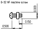
Then get a 8-32 round head brass or stainless steel machine screw 1/2" long, thread a nut onto the screw so you have about 3/16" of threads showing and silver solder or epoxy the nut in place. If you need to make the nut smaller to get it in your hole, grind the corners off or lathe turn them. You can simply just shorten the threads, allowing the head of the screw to bottom out on the outside of the elbow, but trying to get this short screw in this confined area is hard for big fingers. But be sure you do not let it go so deep that it blocks any water from exiting the telltale hole. Use this screw to plug the elbow after the debris has been flushed out.
| Dimensions of the plug screw |
 |
You have a small access
hole (3/8" or so) in the lower
cowling, but that is a lot better than the hassle of removing the lower unit and
then the power head just to get the one bottom bolt of the side cover off.
In the motor shown below, the water flow out the telltale was erratic, no amount of poking with a wire would help. I knew the water pump was fine because just before it plugged the water pressure blew the hose off the elbow because I had forgot to use a tie tape to secure it. And with no water coming out, the motor never overheated. But I wanted to sell this one, so this was the solution. After starting it with this hole in the elbow, some water came out, but poking with a wire dislodged debris giving the steady stream shown in the photo below on the right. It plugged a few times, then more wire poking, I finally got enough of the debris out that it ran for a few hours in the test tank with no other problems.
Shown below on the left by the red arrow is this access hole. Be VERY careful to not over tighten the plug screw into the plastic Ell. It may be better to loose a screw than to strip out the plastic elbow and then have to pull the powerhead to replace it.
| Here is the location of the drilled hole in the lower cowling & the plug screw | Here is the motor running with the new plug screw removed. At a higher RPM, water squirted over 6 feet. |
|
|
|
For you non machinists that don't have taps or understand a screw size and threads, here is a simpler method of doing the same as above. Drill the 3/8" hole as describe above, but get a #8 or #10 stainless sheet metal screw. Drill the hole in the corner of the plastic Ell to a size smaller than the screw. Start the screw in the Ell to get the threads initiated. Remove the screw, cut off the screw threads so that there is only about 1/4" or less of threads showing. Now, you can run the motor to allow the water pump to BLOW any debris out the hole you have created. Screw your plug screw in and see if it is now "Peeing". If not then poke a wire up the pee hole from the outside to free anything plugging it up. You may have to repeat this a few times to get all the crap out, or remove your plug screw, letting the water pump blow out any other debris again.
It is better to take some time doing this to be sure everything is OK than to burn a motor up, thinking everything was fine.
(4) Is the thermostat frozen shut not allowing any water passage out of the motor? Here you will have the tell tale hole functioning, but the motor can overheat.
Replacing the Thermostat :
It is advisable if you are having water pumping problems to also take a look at
the thermostat, since if the water pump impeller had gotten any of the vanes
worn off, this is a location that this chewed up vane rubber material can
collect and plug things up. If your motor is older, you may consider replacing the
thermostat anyway. The word is that the newer thermostats are constructed of a better
material and operate better than many of the older ones.
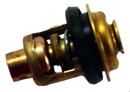
| Standard thermostat used on many74-86 OMC motors | Thermostat used on 87-92 OMC motors |
 |
|
The thermostats are supposed to open at about 160 degrees F.
which will allow the head to heat up just above the point that you will want to
hold your hand on it for much more than maybe 10 seconds. If it gets hot enough
that you can smell burning paint, shut it off as the motor is too hot.
On the motors before 1986 this thermostat is located in the lower portion of the
outside rear water cover, which is bolted onto the rear of the head. The
thermostat is in the very bottom of this cover. The cover can be removed from
the motor without removal of the power head. BUT you will have to remove the
rear cover latch to allow enough room to access the lower RH cover bolt to be
able to remove this cover. You may have to modify a wrench by thinning it
as there is minimal room.
This can be a little tricky in that you need to keep unscrewing the latch screw (1 flat at a time) from the inside, pull the latch lever rearward so that the screw is totally unscrewed allowing the lever to be retracted rearward out of it's hole. Once you get it about 1/2 unscrewed you can hold onto the bolt head and unscrew the latch lever. Now the inner actual latch can be pulled out after it falls off the screw, which then the screw is free allowing the thermostat cover to be removed.
The problem for reassembly is usually that the wafer washer is hard to get aligned over the lever shaft AND then get the latch aligned with the flats coinciding with the flats on the shaft all at the same time. I have found it easier to make up a piece of all-thread the same overall length as the original bolt including the head. LocTite the threads into the latch lever, line up washer and latch on the inside, push the lever with the all-thread bolt in from outside and place a nut on the end of the threads, tighten the nut, and you have saved a lot of frustration.
Getting things back on can be facilitated easier by replacing the bottom cover screw again with a piece of all-thread the same overall length as the original bolt including the head plus another 1/8".
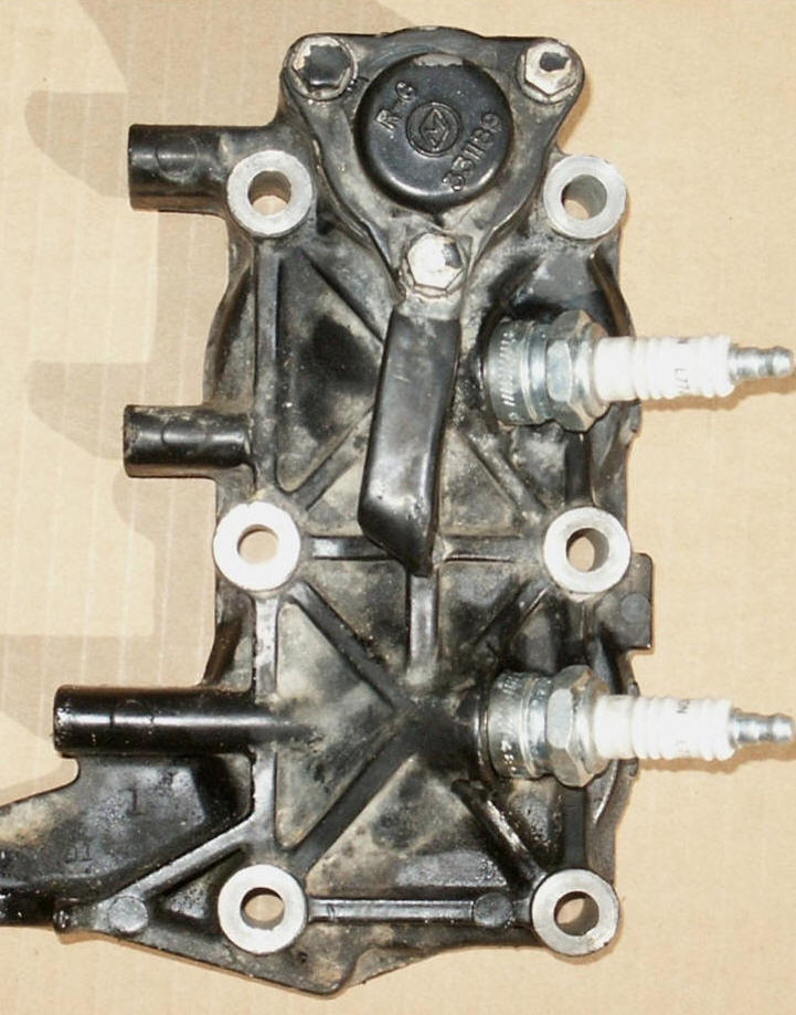
There was also a change in the head and the newer cover has scallops cut (as shown below in center) to allow better access to both spark plugs in about 1977, with the cover gasket also being changed at this time because the cover went from 7 bolts to 8 bolts holding it on. This new head was changed for better fuel burning to help eliminate fouled plugs found on the 74-76 motors when trolling. It had wishbone shaped wedges near the plugs in the combustion chambers. This was supposedly for revised water circulation which was supposed to keep both cylinders more even in temperature and reduced plug fouling.
If you have a older 74-76 motor
and are having fouled plug
problems, you may consider getting a later head. Even the post 87 head
will fit a 74 motor.
| The head showing the 7 bolt thermostat cover for motors from 1974 to 1976 | The head showing the 8 bolt thermostat cover for motors from 1977 to 1986, note the scalloped cut outs for the plugs on this newer head | The head for motors from 1987 to 1992 with the thermostat on the top |
|
|
|
 |
The later motors, at about mid 1987 have a different head as mentioned and shown above. The water jacket of the head that the thermostat is housed in, was changed to place the thermostat on the upper rear, making it a lot easier to access the thermostat. This thermostat is all together different, in that is is encapsulated inside a sealed plastic unit. And the thermostat plate gasket is simply a neoprene O-Ring. When re-installing the thermostat on these, it might be wise to add some anti-seize to the cover threads.
These newer motors from 1987 on, when replacing the thermostat, there is a base seal under the stat. This is a rubber seal ring bonded to a stainless steel base that when pressed into the head is so tight that if you get a stat kit with the seal, many times you can peel the rubber off the base and not even know that the base is still there. The new seal will not fit because part of the old one is still in the head. This seal is pressed in rather tight, so unless the rubber seal is bad, it is recommended not to try to remove it, but just take care of the thermostat. As an alternative, if you scraped the rubber seal part out and find that removing the stainless base is beyond what you want to try, a 1 1/2" outside diameter X 3/16 thick O-ring will nestle into the stainless base and provide a seal for the thermostat. By the way, the cover plate seal uses a 1 1/8" diameter x 1/16" thick O-Ring.
As seen in the photos below, you can see the arrangement of these parts with the thermostat and spring in place, and with them removed. One note when removing this stat cover, it is under pressure of the spring as shown in the LH photo below. Be advised to try to retain this cover when you remove the bolts, as if not retained, this spring can travel quite a distance. In the RH photo below notice the bevel on the right (forward) end, which mates into a rubber seal pressed into the head.
| A 1992 WITH The Thermostat cover removed | Here the thermostat & spring are removed showing only the seal left in |
|
|
|
One suggestion, is that since these post 87 motors are so easy to remove the thermostat, is to occasionally remove it to check for debris that has accumulated inside it, as it is not as open as it's earlier cousins. The photo of thermostat on the right above has some small fir needles and alder leaves that did not make it through, partly plugging it. Just a dose of compressed air and flushing solved this situation.
(5) Next the water pump impeller has to be functioning. Is it possible the drive key fell out when you changed impellers. One newbie non mechanical owner replaced the impeller but had no idea that it needed an impeller key to connect the impeller to the driveshaft, and did not see a keyway cut, just the flat on the driveshaft, that meant nothing to him.
(6) The water pump's outlet grommet needs to be slid into the tube that goes up to the motor when you re-assembled it. If this grommet got folded over when the tube was slid in, your water supply will be restricted or even blocked. This is hard to guarantee it is correct as you can not really see it when you reassemble the lower unit to the midsection after replacing the impeller. The standard length shaft is worse, where the longshaft motors have a larger rubber guide that makes it about foolproof.
(7) If you are absolutely sure that the water pump is good, and the passages are clear, then possibly there is a blockage at the plastic elbow on the other end of the tube that goes into the water jacket on the motor. The way things are put together, you can not get to the lower front bolt to remove this cover plate without complete powerhead removal.
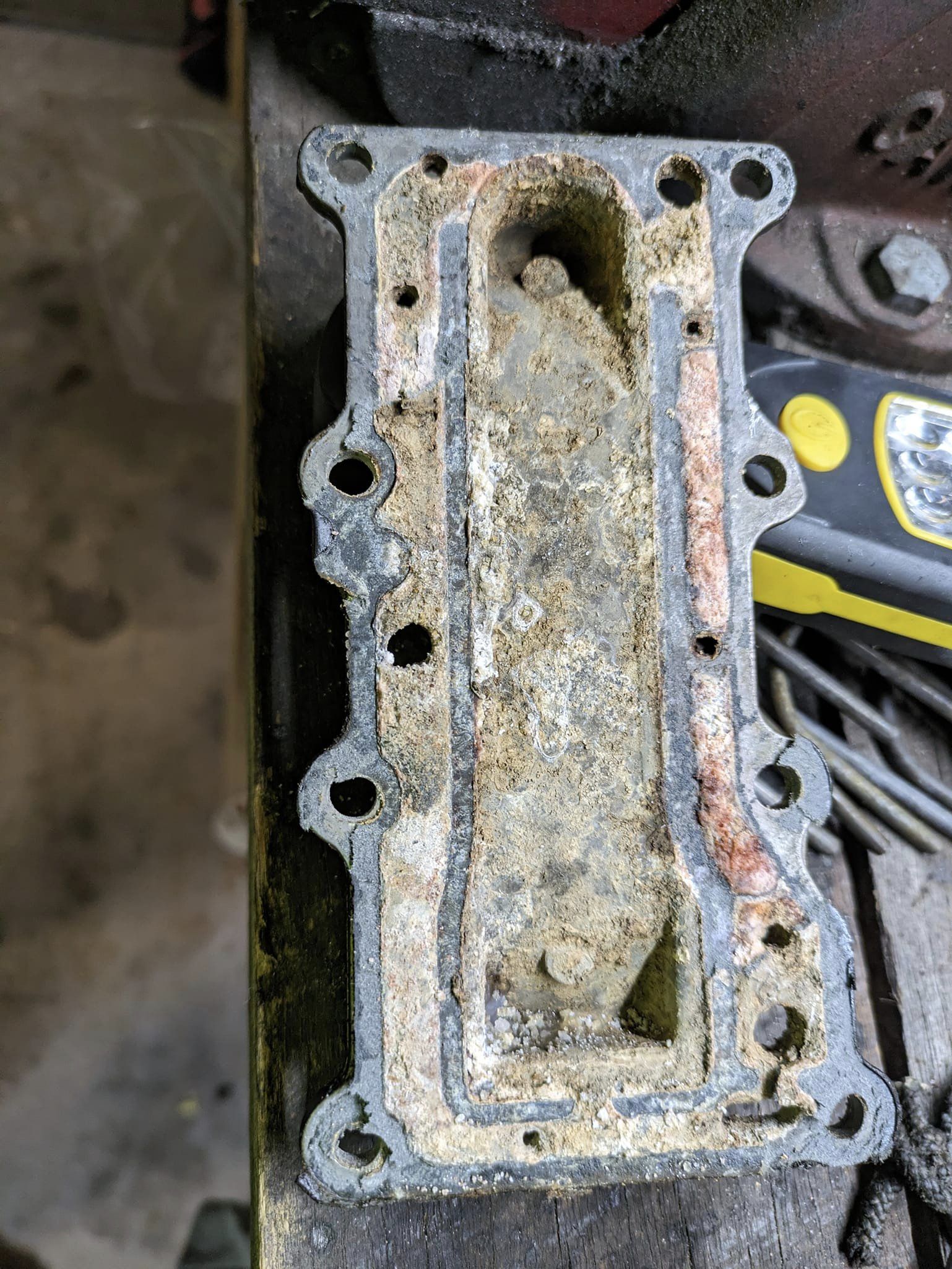
(8) Next the water flows around inside the sidecover. If there is any salt corrosion here it will effect the cooling as it blocks or restricts the flow into the block. This cover CANNOT be removed on the pre 93 motors without removing the powerhead from the midsection as there is one bolt under the RH motor mount that is impossible to get to from above.
|
Here is a very salt corroded sideplate, & the
mating gasket along with it's plate were worse, restricting the water flow |
 |
(9) Usually there will be no blockage in the block itself, but very often there will be in the head and quite likely in the thermostat itself. The simple thing here is if there appears to be a problem, take the head off, remove the headgasket as water passages on both sides of it need to be checked. Once the water gets thru and past the thermostat, you should have no problem.
(10) Next is a hard one, as I have on more occasions than not, seen the connection of the water tubes to and OR from the water pump at the bottom of the powerhead has rubber bushing, they can deteriorate and fold in, blocking or restricting the full water flow into or out of the powerhead. This however can only be repaired by removing the powerhead from the mid-section as it (the exhaust tube) fits into an adapter plate under the powerhead.
To check for this, I would first pull the thermostat and see if it is functioning. While it is out, run the motor for a bit to see if the pump is working, if it is, you will get water all over, but at least you will know. Then possibly pull the head and check for water passages thru the headgasket are clear. While the head is off check the water jackets around both cylinders, remove any debris is found. Reassemble without the thermostat and run again. If it still gets hot then it is a pretty good bet that the water outlet grommet out of the block is deformed or plugged. OR the side plate passages are plugged, (not unusual if it's a saltwater motor).
(11) If you did not get the motor shut down in time when the impeller failed, seizure is not always the end of the world for a SMALL outboard. Usually they will free up when they cool down and aside from scoring on the piston there is usually little damage. These little motors are tougher than some people think. Most time after it cools down it will start back up again. However do not run it other than to see if it starts until you replace the impeller. It also wouldn't hurt to do a compression check to be sure everything is still OK
At times I have seen when the motor is run on muffs, water bubbling out of the shifting rod grommet at the lower mounting area. Any of the above blockages could be the reason the water is bubbling as it may be backing up into the water pump and being blown out of the water pump outlet grommet. OR, more common, you are running too much water pressure on the muffs.
No Overboard Water Indicator as we Know it, Not Used on Early Motors : The water simply was pumped thru the motor, then was exhausted out the bottom of the powerhead into a split section in the exhaust housing. There is a rear chamber in the exhaust housing that is only open on the bottom, slightly below the one 3/8" blubber hole on the outer rear of the housing. This system was common to all the earlier OMC engines prior to these years and was carried over into this series of motors thru 1976.
With this older system it is can be hard for the inexperienced to tell whether your water pump was really working until the thermostat opens allowing hot exhaust water out the blubber hole, as as compared to a motor that uses the newer tell tale system. After the thermostat opens, you get lots of hot water and some exhaust gasses out this 3/8" blubber hole. The one thing I have found however is that at an idle there is not much water blubbering out this hole. If you are not certain, if the motor runs and the block does get so hot that you can not hold your hand on it for about 1/2 a minute, or the paint on the upper rear block starts to burn, the water pump is bad and needs replaced.
On the pre 77 motors the blubber hole exhaust chamber is open into the 6 holes on the rear sides of the lower unit, forcing the water out the blubber hole or being sucked out the lower holes when in the water. Later motors used a exhaust baffle plate (with numerous holes in it) at the lower end of this chamber, this apparently allowed for better breathing of the newer motors since the overboard water indicator pulled water off at a different location.
Back pressure
from the exhaust inside the total housing forces some of the outlet water up
and
it pushes a combination of exhaust gasses along with a watery mix out this upper
indicator hole. When running right and with the boat in the water,
(which places back pressure on the exhaust) there should be considerable water
mixed with some exhaust blowing out this hole.
If you however run it using muffs, you will get very little
spray water out this same top exhaust relief hole. Without
exhaust back pressure, all the water that is exhausted goes out the bottom and
out thru the prop.
After the motor warms up, if you can lay your
fingers on the flat place on the top of the block at idle RPMs and hold them
there for about a minute without a great discomfort to them, (as the
thermostat opens at about 155 degrees) if your engine is running about right.
From looking at parts and service manuals for 1974 thru 1976 it is my
observation that the "New Overboard Water Indicator" was not introduced in
this series until possibly late 1976 or early 1977. I have one 74
powerhead that has no provision for any overboard water indicator of any kind,
but I have another with a model number suffix of G, it has a modified water
jacket that has an 1/8" pipe fitting tapped into the upper section. It
also has some sort of a formed plastic spacer that goes over this section and
the tapped Ell 1/8" pipe fitting going thru both. This main water
jacket area is thin and possibly the plastic was designed to help eliminate
leakage. This threaded hole is located in the upper mid part of the
water jacket. This location could only have been used for a manual start
motor as it would have been in the way of the wire connection terminal block
of an electric start version. My assumption is that this is was
NOT a factory modification, but an owner or dealer modification. Then I
have another same year motor with a prefix S, that has a raised threaded boss
like the later versions on the lower section of the water jacket. The
simple method of converting would be to replace the outer water jacket with a
newer one with the pipe thread outlet and drill a 1/2" hole in the rear of the
lower cowling with a rubber tube connecting them. The photo below shows
the normal outlet position of this modified jacket.
All the 1977 motors that I have seen do have
this
Overboard Water Indicator.
I would recommend anyone having one of these older motors without the "Pee
Hole" to convert it to the newer style, as the is no doubt then if the water
pump is working or not.
This hole can be drilled and tapped at the upper location while this sideplate is still on the motor. I would however place some chassis grease on the drill to pick up most of the chips when drilling. Also do the same on the tap when tapping. I would use a starter drill of about 3/16", then finish the hole with a R drill (.339 dia.) or a 11/32" (.344 dia.) drill and tap to a 1/8" pipe thread. This material is thin, (less than 1/8" thick) and there is a cavity behind it that gives enough room to drill and tap, but don't tap it deep (only enough to get a few threads in the jacket) as pipe threads are tapered, you need to have this fitting tight, pointing down and rearward when finished. If you don't get it deep (large) enough, you can always tap it deeper. It is rather hard to make it smaller if you find you made it to deep/large.
Since pipe threads are tapered, tap it in only about 1/8"to start, then try the fitting. If you happen to go too deep it may bottom out inside, you would then have to shorten the Ell threads of the fitting. A 1/8" pipe Ell with a 3/16" barbed hose fitting is what you need. The OMC Ells #321886 are made of Nylon, and are recommended as they are more forgiving if you need to tighten more. Apply some non-hardening gasket sealer to the threads. If you do need to tighten it in more, you may have to file off some of the metal or Nylon off the threaded screw boss just in front as the Ell barbed fitting may hit it while rotating so you can't get it rotated enough.
One problem with this upper location is that you can not use this location if the motor is a electric start version because it would interfere with the electrical junction block from the power source, unless the upper junction block screw was removed and the junction block was rotated downward slightly, then only use the rear screw to retain this junction block. Not really a good thing.
In the photo on the left
below, is an you can see the actual modified
Overboard Water Indicator
using a OMC Ell. The
bright aluminum protrusion at the bottom of the cowling is simply a aluminum
rod with a .085 dia. hole and the barbed end lathe turned to just have a snug
fit inside. The tubing is clear vinyl 5/16" OD (just the same size
as the hole is drilled into the cowling). An O-Ring of a tight fit is
slid onto the tubing to form a stop for the tube's protrusion out of the
cowling. The beauty of this is that IF the outlet hole becomes plugged,
this tubing is flexible enough to be pulled upward out of the hole and easily
cleaned.
In the photos below you will see the differences between the early non tell tale hole and later water jackets. There is another one similar to the photo on the right, but without the lower threaded overboard hole. On this one, the drill location would be at the intersection of the X on the casting. However this would need to be beefed up on the inside top and bottom of the X to the same height as the X with JB Weld before the hole is drilled to be thick enough to be threaded.
On the right at the red arrow you can see the threaded hole for the water outlet Ell of the newer jacket. You will also notice the lower right bolt hole, which is the one you can not get to without the powerhead removed.
For the hose, I have found
that automotive windshield wiper hose or vinyl tubing works great.
| Here is the actual conversion on 1974 Evinrude | Here is the water jacket off a 1977 showing the newer factory water outlet threaded hole |
|
|
|
This outward hole in the 1977 and later plastic overboard water indicator is small enough (.085 dia.) which is about the size of a wooden matchstick, small enough as to not draw off a high volume of water. From there, the water is routed up the rear of this jacket, over the top, down and into the block. The flow then splits and goes on each side of the cylinders then out the top into the water jacket of the head. The flow splits again and circulates around the inside of the head’s water jacket and out the bottom to the thermostat. It then goes out the thermostat, when the proper temperature is reached, up to the top, then back down the thermostat water jacket, into the lower head, then into the lower block and out thru the exhaust housing’s divided section, out the baffle, then out thru the 4 holes on each rear side of the gear case above the cavitation plate. These holes are there so that when the motor is being run in the water without being in gear, the backpressure is vented out thru these holes. When the motor is in gear, the prop is turning and the boat is moving forward, this backpressure is sucked out thru the center of the prop.
Even after the new overboard water indicator (tell tale) was implemented, the old vent mist holes were left in the upper housing. They may have changed from one to two and in size, but they still are there. The later ones have a plastic cover that acts as somewhat as a muffler. They are there yet probably as simply a relief hole so internal exhaust pressure will not build up inside the upper housing.
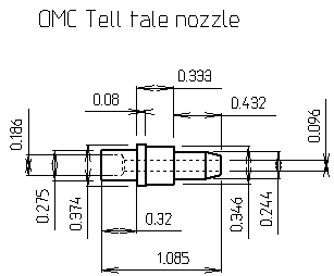
Modify Tell Tale For Easier Unplugging : The Overboard Water Indicator or "tell tale" can get plugged if running in debris infected water or even a bug crawls up inside and dies. This does not effect the running of the engine, but does not give you any indication as to whether the water pump is functioning or not. This rubber tube is routed out the RH rear of the lower cowling, and for the motors from 1977 to 1991 they used a plastic barbed fitting #0321885 that snapped into a .690 diameter hole in the lower cowling and pinched the rubber tube tightly all at the same time.
In 1992 they dropped this plastic unit and simply used a rubber grommet #0334761 in the same sized hole, then poked the slightly different size rubber tube out through the grommet hole. This rubber tube was not secured in the hole and could move up and out of the hole, allowing water to be sprayed inside, around and the motor, not so bad if fresh water, but could be disastrous if salt water.
You can see in the LH photo below and the RH plastic nozzle that once this is snapped into the cowling AND the rubber tube is slid down enough to be also secured to the plastic base by the barbs that pinch into the tube, that it is about impossible to readily remove this just to clear a obstruction, especially while running.
The illustration on the left side is the rubber grommet off the 92 and with my
aluminum nozzle. The dimensions of this nozzle has a very slight larger
ridge on the inner/rubber end. This larger ridge is just enough to allow
the nozzle to be pushed INTO the inside of the grommet enough to retain it,
yet allow it to be readily removed to clear debris. The inner hole is the
same size as the outlet of the earlier plastic nozzles. The upper inner
hole is slightly larger to help from possible more blockages.
The good part about this is
that if this nozzle becomes plugged, while running, I simply pull the hose up
out of the grommet, point it overboard and pop the aluminum nozzle out.
99% of the time the nozzle has some debris at the junction of the outer end of
the rubber tube and my new nozzle. Just blow it out backwards by mouth
pressure and plug things back together.
| On the left is my modified 92, with the original 77-91 on the right | Dimensions of my removable nozzle |
|
|
 |
The 1993 -
2005 motors used just a hole drilled on the plastic lower cowling with the
rubber tube poking out if that. However this tell tale water is tapped
off high on the water jacket as compared to low for the pre 93's, so I'm not
really sure if they took into account and designed around it, for possible
lesser resistance here or not.
Water
Pumps
: Below is research done using Mercury
motors, others should be nearly the same as the water pump impellers are very
similar for all outboards.
|
Damage can
be done in just a very short time with no water to the water pump
of outboard motors |
 |
Shown below on the left is the water pump with the impeller on the driveshaft. During functioning, the water is drawn into the housing in a slot in the lower plate of the water pump, (not shown here) but this slot is at the lower side of this photo. The vanes are not as compressed allowing the water to be sucked into the cavity. As the impeller turns on the driveshaft, the vanes compress as the cavity is not centered , but offset or eccentric. This offset forces the water from the rotating impeller out the gap seen on the top of the cavity and up into the copper tube which is located in the 1/2" round hole in the top of the pump housing. Here the tube is secured and sealed by a rubber grommet in the top of the water pump.
When the motor is running, the water in the water pump housing is pushed by the rubber vaned centrifugal impeller upward and into the 3/8" copper supply tube up into the powerhead.
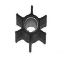
On the photo below, the RH is a new water pump impeller. Seen here is the drive slot in the bottom for the impeller key into the driveshaft.
As said before, this is a
centrifugal pump,
this means that the impeller is a rubber vaned insert setting inside of a
stainless steel housing. Again the impeller is offset to one side so that when
the water comes into the pump housing at the widest part around the impeller and
as the impeller turns the water is compressed and then forced out on the other
side. This is illustrated by the LH photo below.
The outer edges of the vanes are not the only significant part of the water pump
impeller as the circular rubber rings on both sides also act a seal, keeping the
water trapped between the vanes. In the LH photo below the impeller is
installed rotating in the proper direction. This is very important
on these smaller diameter impellers.
| Water pump viewed from bottom side | New impeller |
 |
 |
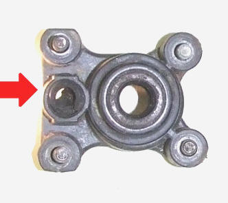
The photo below shows the water pump housing with a folded over outlet grommet. With this folded over rubber grommet is pushed down into the water supply channel of the tube, and the water flow is restricted. This is the most common blockage when a novice, (or even professional at times) does not get the copper supply tube inserted properly when reinstalling the lower unit after replacing a impeller. The tube needs to be round, not sharp, then greased as it is slid together during the reassembly. The grommet ears need to be secure in the pump housing.
What makes it overly hard to reassemble properly (and keep it there during assemble) is that there is not much room and it is hard to see as everything is slid up aligning the driveshaft, shifting linkage rods AND the supply tube into the top of the water pump housing all at the same time. You need to be sure the supply tube just enters into the water pump outlet grommet, then get the shifting rod aligned into the connector block. Now you may have to move the shifting lever into reverse to bring the lower unit closer to the mid-section housing. At the same time rotate the flywheel enough so that the driveshaft splines engage with the crankshaft splines all the while putting pressure upward on the lower unit.
The issue of reassembly of the lower gearcase back to the exhaust housing after a water pump impeller has been replaced has been improved considerably on these motors by the water pump outlet grommet being replaced by a taller one that has a more of a internal taper to it. This water pump outlet grommet has 2 side ears on the sides that hold it into the top of the water pump housing. Be sure that they are in place when reinstalling the lower unit.
Long shaft motors have a 5" fiberglas adapter plate above the water pump. In this adapter is a long rubber grommet that has a long tapered internal hole for the water supply tube to go into. When it is assembled, this longer grommet is self-aligning of the tube into the grommet, so longshaft engines have way less problems when reassembles.
I have seen different styles of these grommets on different years of motors, but never had a clear vision of which was for what until I looked at a Bombardier water pump kit, here it shows each grommet, the part number and for what it fits. All of these grommets are secured into the top of the water pump body by a set of "EARS", as seen in the RH photo below.
No matter how good the impeller is, if the
water pump driveshaft top seal (as seen in the LH photo below
not the red arrow) is defective, you could
still have lack of water being pumped to the block. Here if running in a
bucket, that the water just covers the pump inside, you may see water blowing
out in front and above the lower motor mounting boss.
So, if you
just replaced the impeller and you still get minimal water flow, into or out
of the motor, maybe you should also replace that top water pump drive shaft
seal, which I will bet 98% of the water pump repairs don't even consider this.
| Here a short shaft water pump outlet grommet viewed from the top, is folded over, almost totally restricting flow, shown by the arrow | Shown below is the grommet designed for the long shaft unit (which makes for easier re-assembly) |
 |
|
Some mechanics may install the longer longshaft grommet for better alignment in the short shaft motors thinking this is an improvement which pretty well eliminates any misaligned, folded over grommet problem. However if you do so, the grommet is tall and wide enough at the top where the water tube goes in that it may come in contact with the bottom of the exhaust housing sealing this cavity off.
This can prevent any water from draining back into and then out of the lower unit exhaust area via the oversized hole the copper water tube passes through. However there should be no water in this area unless your upper water tube grommet into the block is leaking. BUT if you do use this longshaft grommet, you will need to drill 2 holes about 3/16" dia. holes in the exhaust housing plate on each side of the grommet location to ensure any entrapped water will drain out of that cavity as shown in the photo on the right below. Shown below are the placement of new drain holes. However location seems to be pretty critical as there is a recess on the outer housing to accommodate the lower rubber housing mounts and the inner boss. These are my second try before getting them into the cavity above, so location is pretty critical.
This photo is of a 1979 exhaust housing, note the two key type slots on the side of the water tube. The hole for the tube has minimal clearance, apparently to help align the tater tube into the water pump grommet upon reassembly. The earlier motors, at least in the 74-76 era had a oversize hole by about 1/8' on each side, but allowed the tube to not be centered on reassembly, creating problems where you can not really see when trying to align this tube.
In the photo on the left are examples of the 3 grommets that I have found, with the newest and tallest on the left. The grommet on the right is the one that appears to be shown in the LH photo of the above photo of the water pump housing.
| At the left is a longshaft grommet # 302497, with a shortshaft # 327035 in the center & on the right is a shortshaft style that is damaged, folded over & restricting flow. Note the "retaining ears" on them. | Shown here by the red arrows is the location I found that should work. Anything forward & out will miss the narrow cavity above. You can see the 2 drain slots on the sides of the copper water tube that can be blocked |
|
|
|
|
|
There for the mid to late 15 hp motors using the round exhaust tube, there is also a large neoprene O-Ring that is slid over the top of the water pump housing. This helps align the lower unit and water pump into the mid section housing.
There is a seal on top of the water pump housing which the driveshaft goes thru. If it is deteriorated, you may get some cooling water being blown out around the driveshaft, cutting down the water to cool the motor.
It everything goes right, I have removed the lower unit, replaced the water pump impeller and reassembled the lower unit back on the motor in 45 minutes. The Clymer flat rate manual says it should take 1.3 hours.
If you are having trouble with water flow and need to test to see if the internal passages are blocked, and have the lower unit off, I fashioned a adapter that attaches to a garden hose. This was simply made up out of fittings I had around. It uses a garden hose adapter to 3/4" pipe, then reduced down to 1/4" pipe that has a 3/8" barbed fitting. The plastic tubing is about 16" of 3/8". Then a small hose clamp rounds out the unit. You may not really need the hose clamps unless there is a actual blockage, as just the plastic tubing slid onto the copper tubing should give you some indication as if there is a passage.
Using this you should get a water stream out the pee hole and you could also get a pretty good low of water down the exhaust housing tube if the thermostat has been removed, which would be the total of the exhausted cooling water (minus the pee hole water). However remember that if the motor is cold, the thermostat will be closed. This flusher is not a cure all, but simply a test device, but it may help remove blockages however in some instances.
You can also tell if the head gasket, or exhaust gasket is leaking by removing the spark plugs, and if one of them is leaking, water will come out of the plug holes.
| Water-jacket flush adapter | Here the flusher in use verifying water to the tell tale hole. |
|
|
|
One reader however wrote that he took a section of coat-hanger, cut it to the appropriate then put a slight bend in the top end. then put it in a electric drill motor and Roto-Rooted this upper folded over grommet out with success. At least he got water passage, maybe not complete and as good as if it was disassembled then done right, but for him it helped. Here the wire can not be forced too far as it will just bottom out against the block's upper cavity. This however would not force anything out that may be partially blocking a water jacket internally.
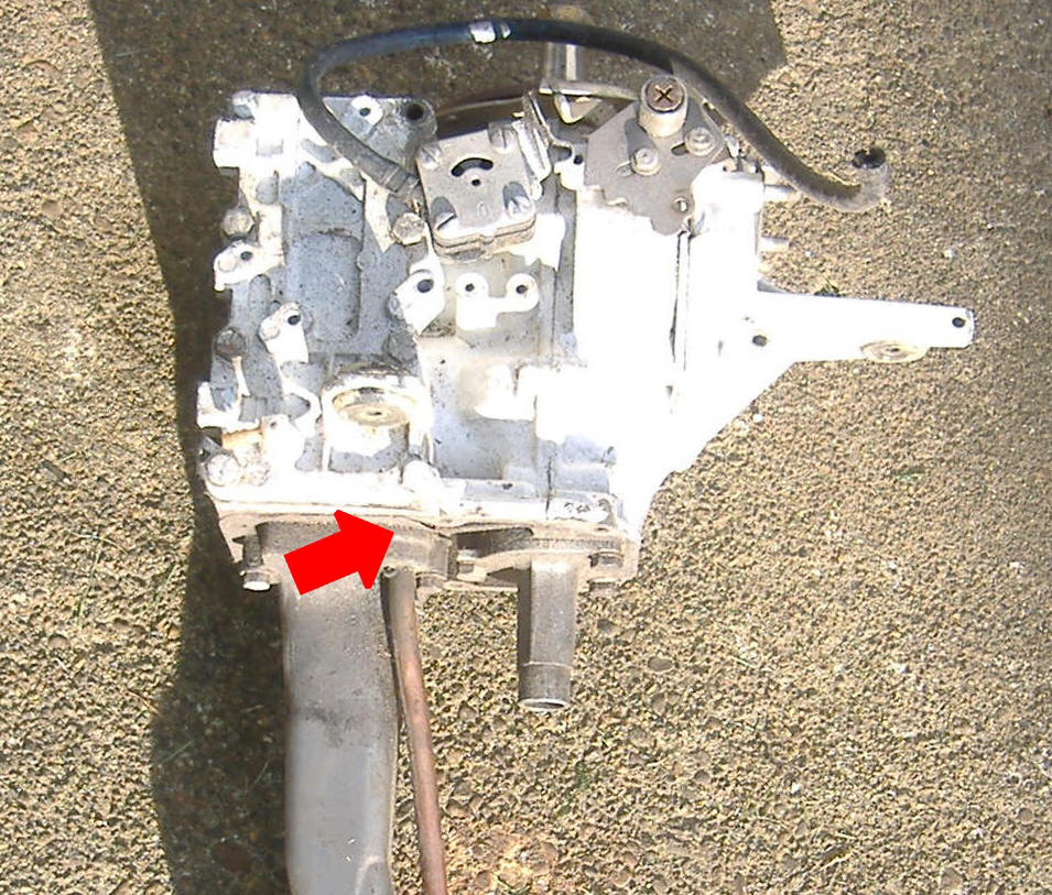
| Here the powerhead is removed from the cowling & exhaust housing with the arrow showing the location of the upper water tube grommet at the upper end of the water supply tube. |
 |
| Note the older or square exhaust tube of the 9.9 hp |
I have one 1989 15hp that I picked up to accompany my 14' StarCraft
boat. This was a non running salt water motor.
Compression is 120# on both cylinders (the reason I got it). After I got the ground under
the coils cleaned, I got spark. But the carburetor was missing a
couple of parts, which were still available. I got it running, but
with no pee water. I knew the thermostat was clean/clear, and
trying to poke a wire in the pee tube did nothing. I then
disconnected the tubing from it, and blew compressed air backwards into
the water passages. Still nothing when running.
I tried to remove the head, to be able to look inside, but all the head bolts were so tight that all
the pressure I could put on a 1/2" ratchet handle did nothing. I
then tried the sideplate cover bolts, they too were seized. This
scared me. It was
pretty obvious if I really tried, that I would twist NUMEROUS bolts off.
BEEN THERE-DONE THAT before and the order is to avoid this IF POSSIBLE.
OK, the only thing left was to pull the powerhead, which was stubborn in
letting go from the midsection, but perseverance prevailed and by using a
dull wood chisel from the rear under the head, in the area of the gasket, I broke it loose from the
base gasket.
In the photo below, you can
see the situation of this motor. The water inlet to the block was
completely blocked, while the outlet was close behind. OK yes, I did
twist off one of the exhaust tube bolts, but, I see no real problem when
using only 3 bolts here.
| Here you see the bottom of the powerhead showing the salt corrosion on the exhaust tube | Here are both water tube grommets badly deteriorated |
 |
 |
The first flush revealed enough debris that it was evident this was loosening some of the internal salt corrosion. Also on the second refilling, it was evident that some internal blockage was removed as the amount of Salt Away was about 4 times more of what the first filling was. Each time I flush, more debris is left in my catch bucket. This process was repeated about every 6 waking hours over a 3 day course.
I am very confident that this will clean the internal water passages, (maybe not completely, and I hope I got enough to not insulate the transmission of the water to cool the block), but enough to get this motor running again. I hate to go this route and leave seized bolts, BUT if I get it running and flush it when I use it in salt water, (and considering the compression it has) I see no reason for the motor will need to be tore down again in it's lifetime.
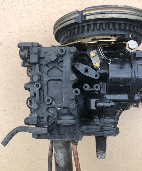
Now in reassembling the question is, what if there is still more debris inside that becomes dislodged over time and plugs the pee hole which is in the bottom? OK, why not move the pee outlet hole up to the top of this sideplate as shown in the previous modification? By looking at the inner parts of another removed sideplate, if I stay centered horizontally of this sideplate, there should be no problem. Here I added JB Weld around the area, building it up to the thickness of outer edge of the sideplate. Then I drilled and tapped for 1/8" pipe. I had a spare factory Ell that I had purchased years ago, so now is the time to use it.
Now do I plug the old bottom hole? It may be best to leave it, but make a plug for the short rubber outlet hose, then I would still have access to it as a secondary outlet to back flush if needed, but not have to remove the powerhead again.
I can not count how many times, I pulled the lower unit, in trying to track down why it was not pumping water. Finally, I remembered an instance on my Yamaha T8. I had greased the impeller vanes as a lubricant. OK, I pulled the impeller out again and cleaned it of all grease, then lubricated it with Lemon Joy. BINGO, we now have water. For some reason the well lubricated vanes were thumbing their noses at me.
One thing that I am happy with, is that the new overboard water tube is now clear Vinyl. I can now see just how much water is coming off the motor.
| New overboard water Ell on the upper sideplate |
 |
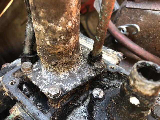
Changes in the Water Inlet / Outlet Grommets : Below you will see photos showing swollen/deteriorated water tube grommets that are located in the exhaust pipe where water enters/leaves the block. Some of these grommets appear to be deteriorated by being softened by fuel/oil mixed in the exhaust. Others (usually the intakes) have evidence of salt type corrosion inside the exhaust pipe upper flange recess, damaging the grommet.
There are two different
grommets, (1) from 1974 to 1984, (2) 1985 to 1992. Have you
heard the phrase "Unintended consequences of well intended acts", well
this is apparently what happened in late 1984, because a different grommet
was used from 1985 on. In
use, the early grommet was slid on to and up the inlet tube against the
flange, which was then inserted into the exhaust pipe from the top, using
the rubber grommet's compression to force the copper tube's flange to bear
against the powerhead gasket between the lower part of the block and the
exhaust pipe upper flange.
In 1985 a new two
diameter grommet was designed so the tube's flange was supported by the
bottom lip of the exhaust pipe with the grommet slipping in on top,
theoretically making a better seal at the block. However with the
engine’s heat and unburned fuel/oil, this could swell the grommet to where
it could restrict or even cut off any water either to or from the motor.
Now somewhere along the
life of these motors, they could have been worked on and who knows where
the grommet was placed during the repair. So, do not go by just the
year of manufacture as to which way they may have been placed when you
tore it apart. OR this could have been done at the factory by
a new employee, or as an experiment.
| Here the old style grommet #0324045 | New grommet #0330426 |
|
|
photo to come |
In the photo below on the left, disregard the yellow flashlight that is supporting the exhaust tube for holding it during the photo.
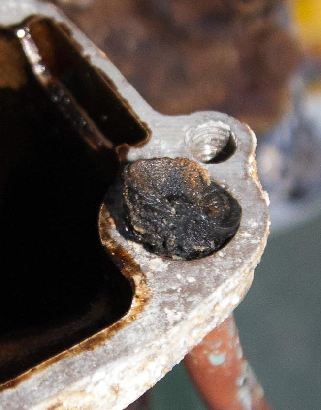
One e-mail correspondent who reads this article fought his cooling system failure for over a year he even took it to a mechanic who tore the powerhead off and replaced the inlet grommet in the exhaust pipe. Still same problem. He, a year later tore it apart himself and found a partially collapsed powerhead outlet grommet. The water pump and thermostat was doing fine, just that the water could not exit the powerhead. He sent the photo in the middle below. Why the mechanic did not catch the other bad grommet is a mystery. This is something that can happen, but not that often. Hopefully here we can spread the word and save somebody else some aguish down the road.
Occasionally the connection of the water tube from the water pump to the bottom of the powerhead that has a rubber bushing or grommet can deteriorate and become folding in, blocking or restricting the full water flow into the powerhead. This location is indicated by the red arrow in the photo on the left below. However this grommet can ONLY be replaced by removing the powerhead from the mid-section as it fits into an adapter plate under the powerhead.
Occasionally you may encounter a motor that will pump water at a lower speed out the pee hole, but as the motor RPM is increased the stream will dwindle. If this is the case look at the scenarios illustrated below. You can have a partially blocked powerhead grommet that when full force of the water is exerted on it, it will totally collapse.
The blue arrow in this same photo indicates where the main exhaust (used) water flow exits the block. There is another short 3/8" copper tube that diverts this warm water down, cools the exhaust tube then out thru the relief holes in the sides of the lower unit and or out thru the prop.
In the RH photo, the owner of this
motor was having "steaming conditions", however there was slight
tell-tale water spraying, but the motor was overheating like 200
degrees, not enough water was getting in to cool the motor, but it was
peeing slightly because the overboard water indicator gets the water first
before it goes into the motor. What little water that was getting into the block
became steam because the motor was so hot.
| Here is the actual inlet grommets in the later exhaust tube with the Blue arrow which is motor's water outlet. The Red arrow is pointing to the inlet. | Shown here on the upper left is a deteriorated, partially plugged exhaust tube outlet grommet. It should look like the inlet grommet on the bottom right | Shown here is a almost totally collapsed inlet grommet on a early 74-76 exhaust tube, evidenced by the relief slot on the side of the housing |
|
|
|
 |
| Newer round 15 hp exhaust tube | This is off a 1985, notice the slight differences in the casting, but the water tube locations are the same, AND the grommet on top of the flange | This one is off a 1974 |
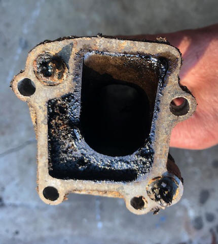
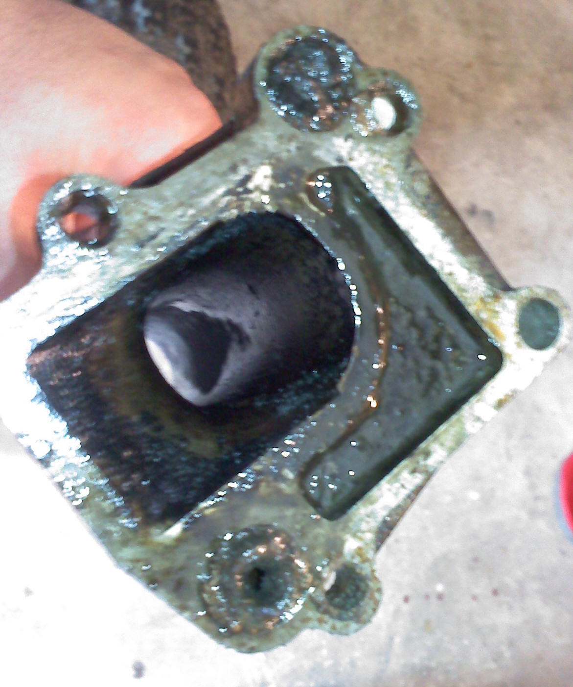
In the RH photo below, there obviously was no water entering the block and from the whitish debris it is obvious the motor was a salt water motor that probably did get flushed enough. It also would be evidenced of a motor that had not been ran for a considerable length of time. The LH photo had minimal water entering the engine but none leaving so essentially both motors were overheating and had no tell-tale water exiting the motors.
| Totally blocked outlet water grommet & almost totally blocked inlet grommet | Here is another bad situation with a clearer photo, where the water inlet (lower RH) is totally blocked & the outlet (upper LH) is partially blocked |
 |
|
In replacing an impeller, always
check the water pump's top seal, as just replacing a impeller may not really
do the job if that top seal is leaking.
Also when you replace a old impeller, if it had veins broken off and unaccounted for, you may have a chunk of rubber stuck in a cooling passage somewhere. Sometimes a situation like this the motor will operate and water will circulate and exit at lower speed, but when the RPM is increased, the higher pressure, because of the higher RPMs, this partial blockage becomes complete, causing an overheat as evidenced by the LH photo above. The same basic thing can happen if you have a swollen or partially blocked upper water-tube grommet, if this is the case it will require the powerhead removal to replace it.
Shown in the illustration below is the flow of the water thru the motor. It first enters the motor by way of the tube in the bottom plate. Then it goes into the RH water jacket with a slight amount allowed to go overboard as an "tell tale" indicator that the system is working. This overboard water indicator is commonly called the pee hole by many outboarders. The water coming out of it will not be hot because it has not had time to circulate thru the block's water jackets. It may be slightly warm but probably not enough for you to really tell if your put your hand in it. It may be slightly warmer before the thermostat opens allowing more water to flow thru the motor.
The bulk of the cooling water goes on into the rest of the sideplate water cover and back out into the block. Here it travels around the sides of the cylinder then out the top and into the water passage of the head. From there it goes to the thermostat, out into the thermostat cover then back out into the head and then back into the lower block, out into the midsection cavity then out thru the relief holes in the lower unit and/or out thru the prop. When in the water on a boat it then goes out thru the holes in the sides of the lower unit.
Any restriction before it gets to the thermostat will make the motor get hot. The thermostat is near the last of line for the water to reach, because it has to be the controlling point allowing the cooler water to do it's thing for the motor before the thermostat makes contact.
In the illustration below, this is of a pre 87 motor as evidenced by the bottom location of the thermostat, however the post 87s flow would be the same.
| Water circulation thru the motor |
 |
The water passage first goes up and into the sideplate. Shown below is the block on the right. In the center is an plate
that has holes allowing the water to get out to the outer water cover sideplate.
On the left, you will notice a 3/8" hole in the bottom LH side of the sideplate
cover. This is where the overboard water indicator Ell (tell tale) hose
fitting is
tapped into. Replacing this fitting without pulling the powerhead is
challenging because you can not access the bottom front cover bolt because of
the motor mount above it. However a reader found a way. "I
was able to replace the fitting without removing the powerhead, by cheating a
little. I removed the 3 bolts for the engine grommets. That gave me
about ¼” play in the lower cowling, which was still not enough to rotate the
fitting as the hose barb would still hit the cowling – until I cut off ONE of
the hose barb segments. It threaded right in after that".
If there is a large degree of blockage at any of these holes, (this is usually not the case however) water will not get into the main motor and to the thermostat. The normal debris blockage is usually in head near the thermostat or the water jackets around the cylinder walls in the block.
This sideplate can not be removed unless the powerhead unit is removed from the mid section because there is one bolt under the RH motor mount that is impossible to get to while the motor is assembled to the lower cowling/exhaust housing.
| Water jacket sideplate covers & block showing water passage after the block has been removed from the exhaust housing |
|
|
I will not go into details of changing
the water pump or thermostat as that is covered in the other articles, but try
to give here direct pointers as what to look for if problems are encountered.
Again, though for a refresher, if you do not get any water coming from the
overboard water indicator and you can not lay your hand on the top of the block
for 30 seconds or so, shut the motor off before you ruin it by overheating,
damaging the rings and seizing it up.
You can "smell" and "feel" an overheat condition. You can also buy a "temperature stick" that works like a crayon. You place a stick mark on the head and run the motor. If the stick melts, it's too hot. These sticks come in various temp ranges so you need one for the temp range of your engine.
Outboard motor impellers/water pumps can fail if air is introduced. This can happen if the motor is not deep enough in the water, or the exhaust tube gasket is leaking, and the upper water pump seal is also leaking, allowing exhaust gasses to be forced into the impeller area. They make good water pumps, not so good air/water pumps
Flushing a Motor :
It is highly recommended
that after a day of fishing in saltwater that you run it with muffs. If
it is the post 93 series, then there is a FLUSH fitting on the upper front RH
water jacket. This is designed not for running the motor, but for a
non-running flush.
There is also a couple of anti-salt solutions, one being Salt-Away. These chemicals when used as a flush are designed to neutralize the salt residue left in the motor if it was ran in saltwater. Here you mix a portion of the solution with water, run the motor, when warm shut it off with the solution still in the motor.
| A self-contained flushing unit using a live-well pump |
|
|
For those of you who only fish freshwater,
you do not realize how fortunate you are.
| Here a muffler on 1987 - 1992 is shown |
|
|
Copyright © 2007 - 2025 LeeRoy Wisner All Rights
Reserved
Back to the Main Ramblings
Page
Originally started 01-20-2007, Last Updated 02-25-2025
Contact the author