 |
Maintaining Johnson/Evinrude 1969 - 1978
|
One thing that I want to
convey here is that I write only on motors that I have actually worked on,
which overs a period
of MANY years, consisting of many THOUSANDS of hours, and then more in
maintaining/updating these articles. They are motor specific, HOWEVER if
you are having a diagnosis issue, my Trouble Shooting article covers MANY more
aspects that may help you diagnose your issue.
CLICK HERE
for access to that article.
OMC (Johnson and Evinrude) utilized a lot of parts
interchange between models and HP of closely associated motors in those days as
it was simple to create "Families" of near HP size motors using the same parts,
which was a great cost saving idea. Here we will usually see many of the
4 hp parts be shared downward with the 3 hp motors, but not upwards with
the 4.5 hp or larger models.
General Observances : The production of this series of 4 hp motors ran from 1969 to 2001, BUT there were MANY changes during this time. These motors started with magneto system (points and condensers), then to electronic ignition being introduced in 1977. The1978s and newer had a different fixed main-jet carburetor. And then the later version starting in 1979 a totally different starter mounted in the new upper cowling and was used, and at that same time the remote fuel tank was abandoned, with a fuel tank in the upper cowling. At this same time the carburetor was changed somewhat by adding a fuel shut off in the carb necessitated by the cowling mounted tank. On this article we will cover a Johnson first and second years of production motors.
Initially this motor seemed to grow from the previously made 3hp motor. It appears that the factory wanted to cut costs from the 3hp and one would be fiberglass upper and lower motor cowlings, but to do so the standard (at that time) throttle/magneto advance required the front of the cowlings to be open so the timing plate lever protruded in front. For this motor they did a whole new lever on the LH side, rather unorthodox, but it gave them time to develop the newer twist grip throttle system. Matter of fact the last year of production for the 3hp was 1968, but it (in my mind at least) was actually the prototype for this 1969 4hp.
The odd part is that on this version, they reverted back to the adjustable main-jet that the pre 63 3hp motors used.
The most noticeable part of this motor is that what you would normally think the right side lever would be a shifting lever (WRONG) it is a throttle lever. The earlier 5hp had this throttle lever on the left side. This motor DOES NOT have a shiftable gearbox, so it is in gear all the time. Reverse is obtained by rotating the motor 180 degrees. This cuts down on weight and cost of manufacturing. It was designed as a fishing motor, (trolling) for small boats, and it did an admirable job at that for a decent price. It was made to use a remote fuel tank, which was rather new at that time for a motor of that size. It was made with a standard lower unit, OR a Weedless version (same as the older 3hp). The difference was the standard propeller shaft was at 90 degrees to the motor driveshaft housing, while the weedless prop shaft sat at a downward angle. And very seldom seen was the folding driveshaft version.
| Here is the 1970 Evinrude Lightwin version |
 |
It is my opinion that they were designed to compete directly with the Eska and Clinton motors being sold by Sears that at that time were using basically 2 cycle air cooled lawnmower motors. These air cooled outboard motors did not idle down anywhere close to what the water cooled name brand motors did, but being CHEAPER, they cut in to the name brand sales. Some first time fisherman did not really know what they needed, and purchased through a catalog or non fisherperson sale staff, but over time, may have found the error of their ways.
This 4 hp motor does not follow the normal line of progression as far as to yearly manufacturing, therefore it is my guess that they (initially at least) reverted back and cleaned up the warehouse using discontinued/obsolete parts and simplified it (or tried to) as much as possible. By this, it appears the starter was from the earlier 3hp and the carburetor also reverted back to the dual adjustable idle AND high speed knobs. But the fuel pump was the same small square one as used on the other motors made at this same time.
All three of the main bearings are simply bronze bushings cast into the aluminum block, and the connecting rod bearings are again simpler by just being reamed in the aluminum connecting rod. This requiring a richer fuel/oil mix than other OMC motors made at the same time frame.
Statistics For These Motors :
These motors develop 4 hp @ 4500 RPM
Cylinders
2
Bore diameter
1.560"
Stroke 1.380"
Displacement 5.28 CI
Bearings, bronze bushings, both mains
and rods
Johnson Tillotson type carburetor with choke, throat dia. .612" - Carb kit
Sierra 18-7043
High speed jet, adjustable up until 1963, Starting point 1/2 turn out
Idle jet - 1 1/4 turns out as a starting point
Fuel cap. Remote with fuel pump
Fuel mix is Oil 1/3 pt. (22 :1) SAE-40 per Gal
Point gap is .020"
Plug gap .035", Champion J4J or J6C spark plug.
Flywheel key - Woodruff .154" (5/32") wide x .235" thick x .603" long
Flywheel nut - 7/16" NF, -- 11/16" wrench size
Water Cooled - rubber vaned impeller type - Sierra #18-3001
Gearbox oil - 90 W gear oil
Gear Ratio - 14-25
Prop. dia. & pitch- 3 Blade, RH, 8" x 5 1/2"
Shear Pin - 1/8" X 1.00" OAL, along with a rubber shock absorber hub in prop
Prop nut retainer pin - 3/32"
X 1 1/4" cotter pin
Prop nut, brass slotted- 1/2" NF
, with rubber nose cap
Weight 29# for the RW & 33# for the RH
Free Motor : The motor being covered here was initially a gift to my neighbor from his daughter-in-law after his son had passed away. This motor had bee sitting for "A Number of Years" and was totally seized up internally. He needed one for his 10' Columbia fiberglass boat, so maybe this would fill the bill. He asked me to give him some guidance. Well, first we pull the head. WE only twisted off 3 of the 6 head bolts in this process. With the head off, WOW, both cylinders were rusted badly and the pistons stuck/rusted into the cylinders. He used penetrating oil for over a week and every time he walked by it in his shop, he would rap the top of the highest piston with a hammer on a large wooden dowel, but with no movement at all. OK, he asked me what next. Well, we need to remove the block off the exhaust housing and tear it apart to access the connecting rod bolts so the pistons could be driven out the top.
|
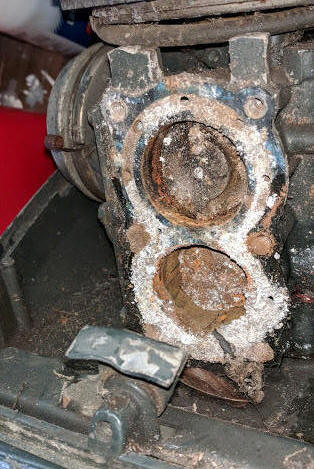
Here is what we saw when the head
was pulled, pretty much indicative of salt corrosion over a long period of time |
 |
First off, we/he needed to remove as much rust from the cylinder walls as possible so that they could be driven out the top. Clean up as much as possible with a wire brush, then inside the cylinders, using a pocket knife and then 60 grit emery cloth, try to remove as much rust as he could, and more penetrating oil.
With the block split apart, which allowed us to remove the connecting rods, then again using the large wooden dowel, pound on the top of the pistons a bit and then alternating onto the connecting rods that had the caps replaced. So back and forth numerous times and finally one moved, and we were then able to remove it, then came the other. Those cylinders were rusted, and from the appearance from a LONG time after being ran in saltwater, then possibly the motor may have been tipped up where water inside the exhaust housing had ran back into the cylinders through the exhaust ports.
The rings were intact on the pistons, but he broke 2 of the 4 in taking them off.
But until we got to honing them, we were not sure that we could salvage this little gem. They were rusted badly, but not deep and for the amount of usage he would give it, with a LOT OF HONING, in all probability the motor could be salvaged. Some parts, including gaskets and bearings were not available, but he had already purchased new rings and head gasket for close to $70. I showed him how to make some of the cover plate and manifold gaskets, by using bulk gasket material covering the part, and a small ball peen hammer tapping around the edges of the metal part.
Here You Are : Since he had no idea of what all was needed in this rebuild, and I was his coach, UNTIL he apparently had a chance to really sleep on this project and evaluate the situation. I then became the new owner of lots of parts, (as seen in the photo below) like I needed another hole in my head. About the only reason (my sane mind?) that I even accepted it, is that I had already started this article, so why not continue and finish it. No sense to tear apart a perfectly good motor just to get information and dimensions for writing an article.
First off, here I needed to see if I could get the powerhead repaired enough to justify any other work. The more I dug, it looked like there MAY be a possibility that I could salvage it. LOTS of work, but possible.
Well, it only took a couple of years before I got around to tackle this project, thankfully all the parts were still in their boxes.
| Here you see the motor, (all in pieces) that I will be covering here |
|
|
There being numerous replacement parts unavailable, or if so, at an exurbanite price, and/or existing ones worn considerably, this project can probably be considered a Red-Neck repair, and is not very high on my priority list.
The one good thing that everything under the flywheel (points, condenser and coils) looked brand new.
The cylinders were honed until MOST of the pitting was removed, going out to almost .010" oversize.
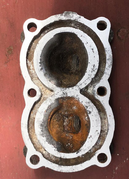
The head was warped enough that it had to be sanded down flatter by laying a sheet of 80 grit sandpaper on a flat surface and doing a figure eight with the head on this sandpaper while pressing down on the head.
| Here is the head after resurfacing it, not perfect, BUT? Before cleaning |
 |
Piston Rings : These rings are rather delicate being only .061" wide X .055 thick with a bore diameter of 1.567". (1.580" honed out bore)
Installing Pistons : When installing the pistons, they need to be positioned properly for the engine to run right. These pistons, (like most 2 cycle) are designed so that incoming fuel does not flow over the top of the piston and out the exhaust port. To make this happen the pistons are designed with a abrupt upward lip on the intake side.
In the photo
below you see an illustration of the orientation of the piston, with the sloped
side toward the exhaust. Here the top of the piston, on the intake side
(spark plug) is designed so the fuel is directed IN and UP, more like being
trapped on that side at the end of the intake stroke instead of allowing it to
be blown across the top of the piston and loosing some of the fuel mix out the
exhaust.
| Here you see the piston orientation |
|
|
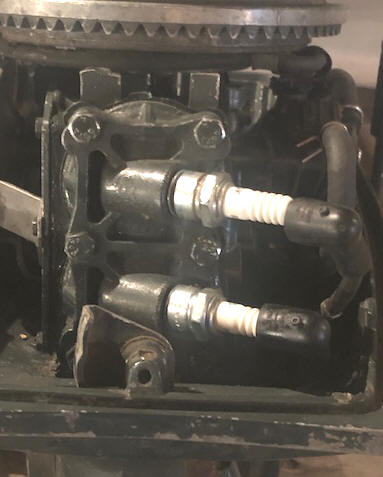
One thing on these motors, if you remove the head, it may be a good idea to mark the TOP. However the spark plug holes are offset to one side (to the RIGHT). On this model the spark plug locations are designed to match the contour of the tops of the pistons. The head needs to match the top protrusions of the pistons allowing for the combustion (spark plug side) like in the photo above which would be the RH side here. This head can be installed upside down and will run, but will not run efficiently, as it can not utilize the fuel from the intake ports as designed. And the top corners of the piston ridge may hit the head.
The top (upper area) of the head has a slight 1/8" X 3/8" protrusion slightly positioned to the left. The head gasket also has a mating protrusion, this is an indicator which needs to be in the UP position.
| Here you see the spark plugs REALLY offset to the right |
 |
Powerhead Bearings : The center and lower crankshaft bearings are cast in bronze bushings (no rollers) and the connecting rod bearings are simply a bored and reamed hole in the aluminum connecting rod, very similar to the Briggs & Stratton lawnmower bearings. The top main bearing is a caged needle roller bearing with 27 needles.
With this
bronze type rod bearing, being mandatory that this motor use
a richer fuel/oil mix (24-1) than currently recommended for the modern needle/roller
bearings.
| Exploded view of the 4 hp powerhead unit. |
Lower Crankshaft Seal : One thing that seemed odd when I into into this project, is that there was no lower crankshaft seal at the block, nor attached to the upper driveshaft like the 5, 6 and 8hp models. Below the lower crankshaft bearing, in the block, is a groove below it for what seemed like may have been designed to accept a seal, but upon investigating, this recess was apparently just for a upward protruding ring on the upper part of the clamp bracket/ exhaust housing that was for block alignment. There is a shallow circular groove in this alignment bushing that could possibly accept a 5/8" ID dia. O-Ring.
OR, maybe with this motor requiring a richer fuel mixture, that in itself, being more oil settled at the lower part of the crankcase, and may have been enough in this small a motor to seal it. ??
Now here is something else, in the lower main bearing journal of the crankshaft is a small woodruff keyway. At each mating bronze bearing, on the sides of this bearing is a small cut at the exact distance down as the keyway. It seems that maybe this could be a method of distributing any accumulated oil throughout the bearing.
Thermostat : These motors DO NOT use a thermostat, probably, (1) to cut costs and (2) since it is a small enough motor, they possibly then designed it so the size of the water passages through the head gasket are enough to balance between it being warm enough for full combustion of the fuel AND yet enough flow to keep from overheating.
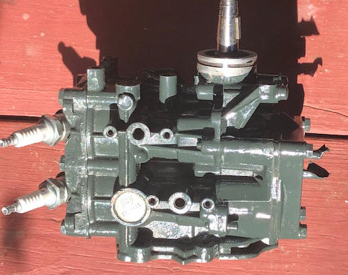
| Here you see the rebuilt block |
 |
Magneto Ignition, Points & Condensers : If the ignition is magneto type, using points and condensers, the points were universal from the 1.5 hp up to 30 hp from 1952 to 1976 and then even to some 40 hp motors to 1973. Condensers pretty much followed this pattern from the 1.5 hp to the 35 hp at 1976 (excluding the 9.9/15 which are different).
On these motors, all
the points are set at .020". If you get a motor that is not firing,
pull the flywheel then clean up the points with a point file.
The last point file I purchased (2009) cost $7.50 from a auto parts dealer.
Sometimes all you are doing is to just remove oxidation off the contacts
if the motor has sat for some time. This can be usually
remedied by running a point file thru the point openings to freshen up
the contact metal.
Most of the service
manuals say to replace the points if worn or burned. Well, take it from me you
can usually clean them up for many more hours of run time afterwards.
However if the points are really pitted, that is a sign that the
condenser is not performing to capacity. If this is the case, then
it is recommended to replace them, along with the condenser. The one thing that does wear is
the points rub bar if it has not been lubricated from the last repair.
If you replace the points and still have running problems, you may well could have contaminated the point surfaces with oily fingers. If this may be the case, remove the flywheel, rotate the crankshaft until one of the points are open, wash it off with lacquer thinner, rotate and do the other set. Then insert a section of brown paper shopping bag in the points, rotate the crankshaft until the points close then pull this paper thru the points. This should clean them.
This older ignition using condensers,
if they start to break down, the motor can start and run for a while, but when
things warm up, the condensers, and or coils can begin to short out internally
which may cause the motor to die. You can crank until you are blue in the face but it refuses to start.
Let it set for an hour, which allows these components to cool down and it MAY
then restart. Time to change condensers, however hang onto the old ones as
long as possible as the newer manufactured ones have a reputation of not being
made that old high quality.
A condenser is simply a lot of aluminum foil wrapped
between waxed paper as an insulator. If the paper starts to deteriorate,
after running for a while, the metal will heat up then expand. IF this
happens in a location where the insulation is bad the metal shorts out to the
next wrap, nullifying or shorting out so no output is achieved.
But IF this is the case, many times when the condenser cools down, the short
goes away until it warms up again. Once it has done this process a few
times, then the short becomes rather permanent and the condenser can become inoperative
If that driver coil (under the flywheel) starts to fail, is cracked, or starting to melt down,
or whatever, there is a
possibility that it would also operate when cold, but fail by shorting out when heated
up by the running of the motor. However do not just replace them because
they are oozing black tar like goo. They may still run for some time.
For a more in depth article on magneto ignition along with fine tuning the point settings CLICK HERE. This article is directed mainly at the 1974-1976 9.9/15hp OMCs, but the principal is the same for about all of the magneto ignition OMCs even with those that have external coils.
Coils :
Coils for these points
and condenser motors are the same from 1949
mostly up thru 1973 from motors 5.5 hp thru 40 hp. This motor's
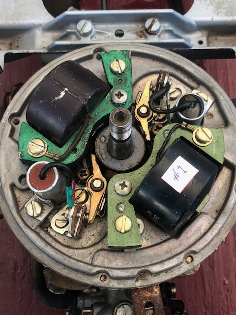
coils are mounted on the timing plate under the flywheel.
These coils, especially those in the 1960's motors have a reputation for
cracking and allowing moisture in and then starting to break down,
creating problems. The factory (or supplier) changed the plastic
formulation on the coils at some stage and the replacement ones are
considerably better. If the coils have cracks that you
can see, they maybe also have cracks below which could be allowing
electricity to short out to the plate. If you are on a tight
budget, remove the coils, dry them out, then paint the cracks with a
thick paint or epoxy, which MAY get you by.
About 60% of the older motors I have had, needed one or more coils replaced,
and the current replacement costs range from $20 to $25 each,
which would be financially unviable for someone not working on their own
old motor with the price of labor at $95 an hour to not replace them.
But the mechanic is covering his behind, because of you possibly later having
one/them fail and he would get the
motor back for free repair only to find that in his saving you money he
actually got an unhappy customer and him a repair where he felt he had
to cover at least part of the second repair.
After doing some web surfing I found a website by Doug Penn where he showed on a video how to test both the coil and condenser of older OMC outboards. CLICK HERE for a coil testing video, and HERE for a condenser testing video.
|
Top view of the
really clean magneto/timing plate with both the points, condensers & coils |
 |
Recommended Spark Plugs : The recommended spark plugs for these 4 and 5hp motors were Champion J4J, however if you are using it for a lot of trolling, I go to the hotter J6Js, which is a hotter yet and used mostly in lawn mowers, trimmers etc. , but my thought is with these older motors, where the coils are getting old and these motors need all the spark they can get, especially at a low speed. The R designation is a resistor type which would be beneficial if you are running a depth finder (helps cut out electrical interference). The recommended spark plug gap is set at .030", however with a well used motor where the rings may be worn and may oil foul the spark plugs, old some mechanics may recommend try to open the plug gap up from the normal to .035" or even .045" which seems to allow the plug to run hotter and burn cleaner. However maybe a better solution would be to a move to a hotter plug, like the RJ6C, especially when doing a lot of trolling.
One notable thing on this motor as compared to it's previous 3 hp cousins models is that the spark plugs are mounted in the head at a dramatic angle to the right.
Fuel Pump
:
This motor was designed to use a remote
fuel tank, which was rather new at that time for a motor of that size.
This requires a fuel pump. These tanks are usually 3 gallons as
compared to the regular 6 gallon ones as the consumption for these motors is
less along with 3 gallons are less weight than the larger tanks. The
pump
used on these motors was common on all OMC outboards form about 1965 through
the late 1990s for about all their motors no matter the HP.
This fuel pump seemed to function, (using the mouth blow/suck
method on each fitting) but it needed attention, in replacing the center
filter/ inlet cover with a new stainless steel one in a larger size, along
with replacing the badly corroded attachment bolts. There was already a
new inlet fuel line, which was the only new part on the motor.
The fuel line quick disconnect coupler is the same single line used on all the later motors.
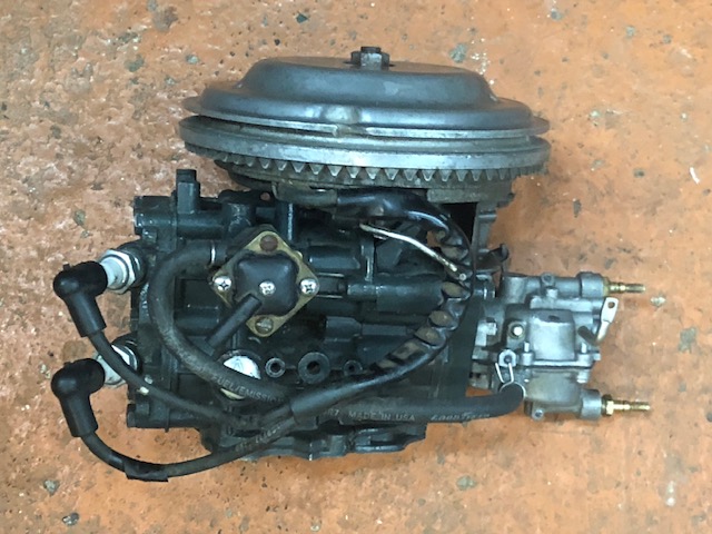
| Here you can see the RH side of the powerhead with the fuel pump |
 |
Carburetor : This carburetor needed a complete disassemble and clean/soak in carb cleaner.
To remove the carburetor, you will need to disconnect the fuel line, the choke lever and both the low and high speed knobs. These knobs just pull off the finely splined shaft straight forward.
You have to You have to remove the starter to access the LH carburetor mounting nut and remove that nut.
Here, you will have to
remove the starter handle, holding onto the rope to keep it from unwinding,
pull the rope in through the hole in the cowling. Tie a knot in it or
replace the handle, now you have the rope free from the motor other than and
being contained in the starter unit itself. Now remove the rear top
bolt (using a 5/16" wrench) from the recoil starter spool mounting
plate that is one of the inspection side plate cover screws.
Then using a 5/8" socket wrench, unscrew the main starter
spool retainer bolt. Very carefully pull the complete starter to one side just
so far that do not pull allow the recoil spring to escape out of the base.
Add a 5/16" NC nut to the starter spool shaft to keep the spool and the spring from coming a nightmare.
Now you can remove the RH carburetor nut, slide the carburetor forward off mounting
studs.
The normal initial setting for the idle (slow speed jet) would be 1 1/2 turns out from lightly bottomed out for either style carburetor. Where the normal starting point of the high speed jet would have been probably 3/4 of a turn out.
This carburetor is fairly simple design, (a slightly different version of the popular 3hp model) being held on by (2) 1/4" NF nuts. The throttle lever is unique here and not on the front like most, but on the RH side of the cowling. This carb has an exit throat diameter of .735". FYI, the manifold inlet diameter hole is oval .500" high by .725" OAL.
There is no breather as was on the earlier 3hp
brother models. It
is the basic simple standard unit and possibly one of the last to use the
adjustable main-jet
style. There is no carburetor cam roller, but simply the
carb arm (#26) rubs on the timing plate cam.
Number 15 in the illustration below is the idle adjustment needle, while #23 is
the high speed adjustment needle. Number 9 being the choke lever.
| Early, adjustable main-jet Carburetor |
 |
The main jet is mounted in the bottom fuel bowl part of the carburetor (also known as the high speed jet), and is adjustable (protruded as a twistable shaft). The upper knob is the low speed or idle adjustment. These knobs are adjustable on the shaft so that once you find the desired setting, you can reset the knobs to a desired number, (usually #1) if it, (the knob) is round, or have the pointer aligned, usually UP. This is accomplished by the shaft being internally threaded to 6-32, lightly serrated, AND split. The knobs have a bore that fits closely onto this split shaft. A tapered head screw being screwed in after the knob is installed, where this tapered head screw expands the split shaft, tightening the knob in place. If you loose that screw, a easy replacement is one designed as a retainer for electrical outlet covers.
Throttle Control : The throttle control lever is located on the right side of the motor and raises about 6" up on the outside of the cowling. This is many times confused with a shifting lever, however these motors pivot 360 degrees for reverse. The Fast, Start, Slow indicators are a decal on the lower cowling behind the lever.
It has a rubber friction tube inside the lower cowling supporting this lever shaft and tension adjusted simply by squeezing the cover for the rubber, using it's 2 mounting screws. Inside the cowling and next to the block his inner part of the throttle arm is then attached to the timing plate by a arm and wire rod, which in turn moves the throttle cam to the carburetor. The speed indicator decals are placed on the top part of the lower cowling behind the lever/arm. There is no Kill button, as with the lever all the way back is enough to change the timing to where it will die, if not then choke it.
| Here you can see the throttle lever & the speed indication decals on the RIGHT side of the motor's lower cowling, (NO TWIST GRIP THROTTLE) |
 |
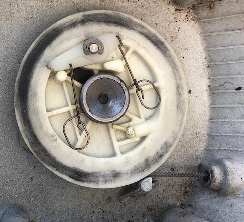
Recoil Starter :
This recoil starter uses a unique
rotating/pivoting vertical gear that when the rope was pulled, the gear
unit pivots up engaging the flywheel ring gear teeth which are on the
under side, engaging the flywheel ring gear teeth which are on the under
side, not outside of the flywheel. This version was initially used on
the earlier 4hp motors and later used on these 4.5hp motors.
This starter assembly that is ALMOST impossible to assemble off the
motor (like most others can be), it can be done HOWEVER IF you have the
right equipment.
| Side view of the 4hp starter unit. |
One unique thing on the 4.5hp is that if the twist grip throttle handle is
advanced to FAST, the ratchet disengages and will not allow the motor to
be started.
