|
|
Repairing a Seized Steering / Pivot Shaft on a 2005 75 HP Evinrude
E-Tec |
My Dilemma ;
This motor was used fishing salmon in
salt water a lot, (the Pacific Ocean and Willapa Bay). It was mounted on
my 18' North River
Mariner boat. My wife was developing a disease whereby she lost her
balance and fell a lot, (even breaking the same bone in her wrist twice in 5
months). That was when I cancelled the rest of my fall salmon fishing in
September of 2015. It soon got to where I became her 24 hour caregiver for
the nearly the next 3 years, whereby the boat and motor just sat in my barn's RV
bay. I would start the motors up every few months or so just to keep them
lubricated (and sit in it to dream). I did get the chance to take it out
two years before she passed away, (our daughter gave me a break and said "Dad,
you need to go fishing and take your son-in-law with you").
But on
this last trip the steering was overly hard to turn, and I assumed, from past
experience, that it was probably the steering cable was becoming seized.
In between taking care of the wife and other projects, I did tear the cable
loose to check it. Nope, the cable was fine. It then had to be
in the motor's steering column. I later talked to a marine mechanic
who was a dealer for that brand of motor, which he admitted that they had seen the same
problem before, with one so bad they could not get it apart, which was not repairable. Needless to say, that I did not come away with a warm fuzzy feeling
that day.
My
towing vehicle at the time was a 1997 Ford F-150 4X4 pickup. But with the
wife's deteriorating condition and needing lots of doctors appointments, she could not climb into the pickup.
So it just sat in the garage as we had traded off her Camry that she could not get
in and out of easy, for a Ford Escape SUV which would also be better to haul her walker, or later her scooter on a rear
ramp carrier.
Then one of the grandson's car's computer
died. The Ford pickup was just sitting unused, so we gave it to him as he
needed reliable transportation. With a lot of time on my hands (yet
being readily available to help the wife of she called the cell
phone), I took
on restoring a 14' Columbia tri-hull boat, (which my long range goal was it could be
later pulled by the SUV).
When the wife passed away, life was in a turmoil for many months. And the SUV was not rated high enough to tow the North River boat, but I had a lot of other projects that needed my attention, so the North River boat/motor just sat longer. I did make a few trips to a couple of lakes with the newly restored Columbia boat however. A couple of years later I got remarried, kept the SUV and later bought another pickup (a 2006 F-150 4X4) which would again tow the North River. It was then that I decided to tear into the seized motor to see what it would take to repair it.
Hence this article was born January 2021.
Here We Go ; So with considerable optimism, or pessimism?? I finally dove into this venture. First off I thought that the powerhead would have to be separated from the midsection, but in further examination of the factory service manual that I had purchased, and digesting the exploded views (as viewed on www.marineengine.com) which indicted that the lower unit (gearbox) had to come off first. Essentially, then by removing the upper and lower motor mounts, the powerhead along with the midsection could be slid rearward exposing the steering bracket. This then gave enough room unscrew the lower steering shaft retainer nut and then remove (downward) the splined lower motor mount bracket. From here, the steering pivot shaft (and attached cable arm) can be removed upward and out of the steering housing.
Problems occurred even before I got the lower unit off. On this model, the shifting rod runs up INSIDE the hollow steering shaft, with a top coupler tucked in close under the front of the powerhead. It is connected to the linkage rod and secured by a 5mm cross bolt, which I promptly twisted the head off of. This has to come off so the shifting rod can be retracted down and out of this hollow pivot shaft, allowing the lower unit to come free.
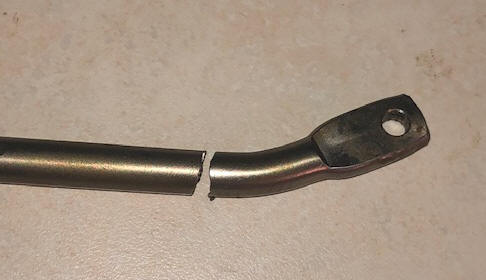
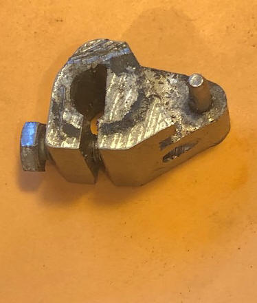
There is not enough room to get in there to even try to drill that bolt threads out of this coupler. OK, but there was about 1" of room in that area and forward of it, which I used to hacksaw the 1/4" dia. shifting rod in two pieces. The coupler and now broken threaded bolt was so corroded, that I had to remove it from the pivot shaft, then band-saw it apart to get the upper sawed off upper part of the rod free. Needless to say I bought a new coupler. But I welded the shifting rod back together while allowing for the thickness of the hacksaw blade. And for reassembly, the Service Manual gives overall height dimensions of the reassembled shifting rod.
| Here you see the shifting rod before the weld repair | Here what is left of the coupler |
 |
 |
|
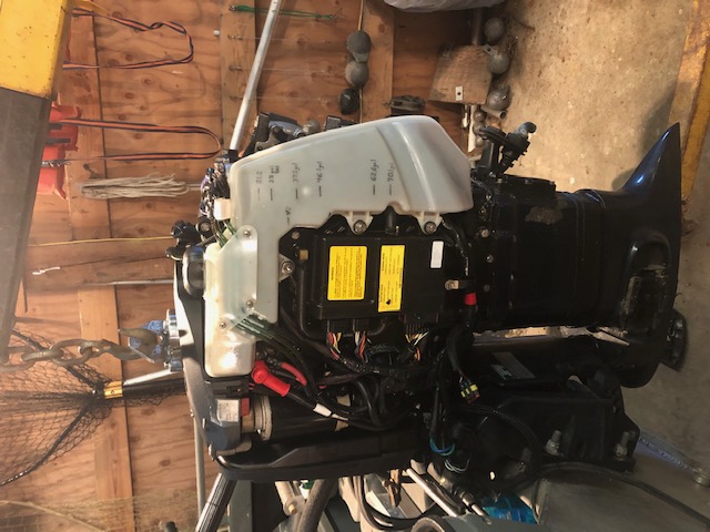
Here you see the motor stripped
down & the lower unit removed |
 |
Then when I starting to unscrew the two upper mount bolts (14mm dia. bolts), the head of one of these bolts (RH) snapped off (it appeared to have been defective, or stressed and cracked when last installed). Using a Demel tool, I ground any burrs off this now bolt stud, as it had to be retracted about 1 1/2" through the hole it was in of the steering column's motor mount attachment. With hopes of later being able to remove this broken bolt from the top rubber motor mount attached to the motor, OR possibly having to also replace this rubber mount assembly. ?? Socket wrench size for these is 16MM.
Also in this project, I probably should say that I as a second owner got snookered when I bought it, as after I got it and a couple of days on the water, one of the three cylinder fuel injectors failed intermittently. It should have had some warrantee coverage as these motors are warranted for 3 years, or 300 hours. This motor was slightly over on years but way short on hours. And I am sure that the previous owner probably knew about the problem, pissed off the dealer, who refused to warrant it even partially. That is when he sold it to me. I found out later by the computer print out, that this injector had 11 intermittent failures before it did the one on me. And the closest dealer who I had to go to, saw me as a bastard calf during his busy season, so any repairs were stalled considerably.
LONG STORY SHORT, they finally
installed a new injector, and on the second trip out after that, I blew that piston because of the previous
scoring in the cylinder wall because of lack of oiling (remember this is a 2
cycle). They screwed up, and should have pulled that head to inspect the
cylinder walls for scoring before they replaced the injector. Resulting in the powerhead needing to be rebuilt.
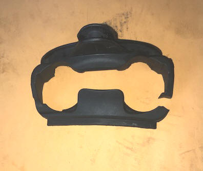
On my repair job, I found a decent sized
rubber boot that came from below the block at the area of the top motor mount
area when it was disassembled. This was damaged so bad that impossible to tell exactly where it
came from. Plus it was not shown on the normal exploded parts list, but I did
get a part number off it and was able to purchase a new one. Now on
reassembly, it appears this boot which apparently is designed to somewhat
waterproof the front underside of the powerhead, looked like it needed to be
installed before the powerhead was attached to the midsection. I did
later find it on the parts list but under the lower cowling page instead of
the motor page. The
previous mechanic that did the powerhead rebuild had cut one side and stuffed it somewhere close to where it should
have been.
In my reassembly, no way could this part fit, maybe since mine was an early production motor and could have been slightly different? In the forward protrusion of it, there is a slit for the shifting rod to go up through. So to install it now, I had to cut away material on the rear to allow it to slide between the bottom of the powerhead and the top motor mounts. I also cut it in two on the Port side so that I can get it in place now. Next, I drilled/burned small holes on each end of the cut part, and wired/Super Glued it together after positioning it in place as best I could. It had groves on the outer top edges and shaped for the plastic side skirts to go into to retain this boot. But on trying to reassemble these lower cowlings, WE could not get them anywhere close to fitting. Seems that the illustration was wrong and I put in on upside down. It was designed to be in place under the powerhead and out of sight when trying to reassemble the cowlings, and the cowlings fitted into into it's grooves. OK, I flopped it over but cut it in two and super-glued each half onto the cowlings. This way it was easier to install, but lost a bit of waterproofing. But I finally found some foam rubber that I managed to cram in that void.
| Here you see the broken off bolt on the Starboard (LH side in photo), protruding from the rubber mount | Here is the boot in question, where I later cut the whole bottom 1/2 off for better fit |
 |
 |
Next was to
remove the 4 lower motor mount bolts, which happened with no difficulty.
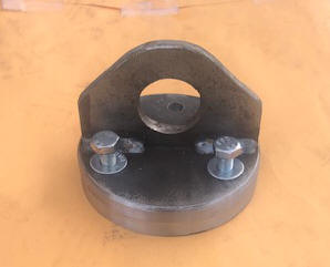
However other tools/machinery was needed to finish this job. One being a hydraulic "cherry picker" car engine hoist, and a lifting ring bracket designed to fit the 3 flywheel puller bolt holes with a large eye welded on top of this plate as seen below. These 3 bolts are 8MM fine threads in case you need to know. Using this system, the motor can be lifted up, off, and rearward, freeing it from the steering bracket. And there was just enough room to not have to disconnect the control cables or any electrical power to the boat, other than the quick disconnect couplers to the power tilt unit.
| Here you see the the lifting ring |
 |
OK, every thing is loose, the motor is slightly raised, but that one broken top mount bolt stud was still holding. I then band-sawed a 2" X 4" stud into a long wooden wedge, driving it between the midsection housing and the steering bracket, forcing the two apart. That did it, and I got everything now loose and hanging free.
| Here you see the wooden wedge forcing the two sections apart |
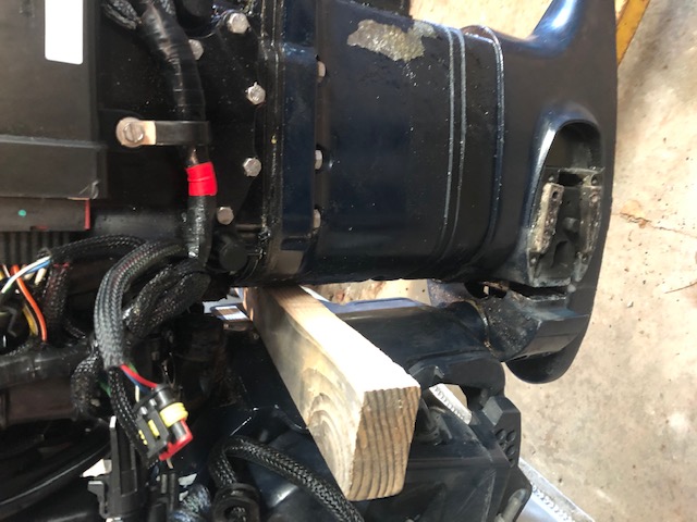 |
In the photo above, you will notice the lower motor mount covers are removed. I found out that this was not needed for this repair, but there was some corrosion under them as seen in the photo above, so it was good that I took them off and can wire brush and repaint.
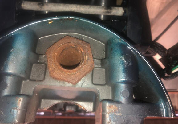
Now to unscrew the large 1 3/4" nut attached to the bottom of this steering shaft. I borrowed my neighbor's 3/4" drive heavy equipment socket and flex handle, but it would not come loose even after trying to persuade it even with a 4# hammer. OK, a 5' length of 1 1/4" pipe on the end of the flex handle did the trick, which broke the nut loose. I found out on reassembly (from the Service Manual) that this nut requires a mild Lock Tite adhesive as a thread locker.
| Here you see the lower steering shaft retainer nut |
 |
OK, got the nut off, now the
lower mount bracket above the nut has to be driven down and off the 1 1/2"
long splines on the steering shaft. These splines, when slid onto and
secured the lower mount bracket assured that the top AND lower mounts were
perfectly aligned. Removing this bracket also proved to be
STUBBORN, even by laying a lead block on the bracket and pounding with a 4#
hammer did not help. I did not want to damage or break this bracket, as a
replacement one cost $162.
Plan #D, heat the bracket at the spline area with a propane torch enough so that it was warm to the touch, and again the lead blocks and hammer, which broke it loose.
| Here the steering shaft unit showing the two upper mount holes, and the lower mount bracket still attached on the splines of the shaft |
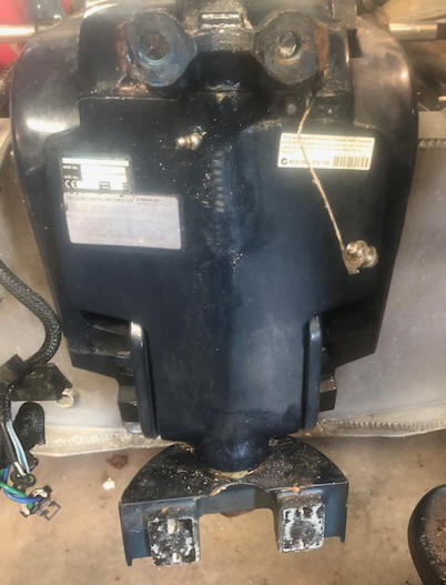 |
Now get the seized shaft out of the steering housing. Here, I reconnected the power tilt wires and raised the bracket unit up to near horizontal position, replaced the large shaft nut, but just flush with the lower end of the threads. And again using a lead block against the nut on the threaded shaft, and pound on it enough got it moving a little at a time. Then disconnect the steering arm (upper part of the shaft) from the cable steering system and proceed to keep pounding on the threaded on nut until it was raised enough to free things so the whole shaft unit could then be removed upward from the housing.
Now came the issue of getting that one broken upper bolt out of the rubber top mount which was still attached to the powerhead. Initially I soaked it with penetrating oil, then using a 4" angle head grinder, ground a flat on one side so I could get a Vise Grip pliers on to provide enough surface to try to unscrew this broken bolt out. Basically, it was stuck so bad, that the rubber mount also twisting along with the bolt stud, and no way to secure the rubber mount itself from the mount's rear metal bracket unit. OK, probably need to replace them.
After re-reading the Service Manual, I removed the center retainer bolt from this dual mount unit, but they were still firmly attached. Then the marine shop that I was buying paint from, their mechanic clued me in on how to remove those mounts. The center bolt actually was in the center of a removable wedge, which with the mounts in their proper location, and this wedge installed which by tightening this center bolt, locked both rubber mounts in place. The key to breaking this wedge loose was to use a long heavy 3/4" rod that I lathe turned a slight taper on one end so it could be lightly driven into the center hole of the wedge, and then pried/beaten sideways/up/down enough to free the wedge from the mount bases.
The two individual mounts then were able to be removed from their pocket location from in front and UNDER the power head block, but above the adapter plate to the midsection. Once they were out, the one that had the broken bolt still in, proved impossible to salvage it. And they are only sold in pairs.
On the outer edges of the tiller arm
rear bracket where these motor mount bolts go through is a 1/4" flat lip, that
secures these mounts from rotating during the tightening process.
And more importantly, they ALSO provide a lip keeping the mount from rotating
when being disassembled, allowing the bolt to be unscrewed. One of
the lips
was broken off on this unit (and had been for some time), which could have caused a major problem if that bolt was also
seized. My neighbor farm/logging repair shop did a good job of welding a
new lip in place for $30.
Very possibly when the bolt head broke off
on this mount bolt, it was a blessing, as with the threads seized as bad as
they were in the rubber mount, where I could not even get it apart once I had it out in the open,
the only way to have removed it/them would have to have used a Oxy/Acetylene
torch and cut the bolt heads off, while hoping to not ruin other close parts of the
motor in doing so. But maybe a layer of asbestos above to protect the
delicate motor parts would help. AND remember on reassembly, use anti-seize
compound on all the threads.
Now before installing the new mounts, there was some oxidation at the bottom of this cavity for the Starboard side mount. I ground most of this out, then blew the grit/dust out with compressed air, then painted this inner hole with zinc phosphate. When trying to install these new mounts, for some reason the Port side one did not want to slide into the close fitting compartment that housed them. It appears they were not really designed to be installed this way (with the powerhead still attached) and one bolt head in the bottom front was in the way. I then had to grind a little off the inside of that mount base to get it to slide into place.
Clean & Reassemble ; After cleaning all the gunk, grease and rust off the parts, what I found was not to my liking. It seems that this steering shaft unit was made from regular steel and all of it POWDER COATED, including all the shaft bearing surfaces (but not the threads). This unit is made in two parts (the arm as a forging, and the shaft welded to the arm). I never dreamed that marine engineers would go that route. I would have thought that the shaft at least would have been made from stainless steel to combat rust, which could have just as easily been welded to the steel arm.
|
Here you see the
corroded (deteriorated powder coating) on the steering shaft |
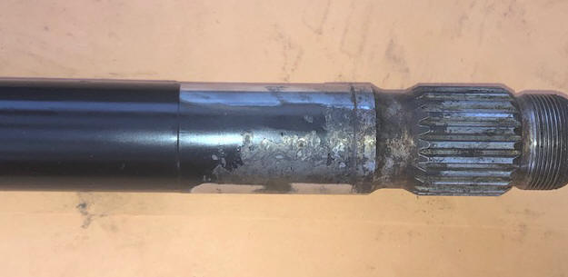 |
And I will not pay $220 for a new steering shaft assembly, especially if it is made the same as this one.
| And here you see the newly sanded steering shaft surface, corroded seal area & the grease slot for the bottom bushing |
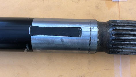 |
To remove the rust on this shaft, I had to
band-sand both of the bushing areas of this shaft with 180 grit belt, removing any
partly worn powder coating there, leaving a few pits/wear rings, (especially
in the seal areas) not ideal, but I thought possibly to push those new seals inward farther,
just enough to gain a little better sealing surface. But after
getting the old bushings out, NO on this idea,
as the bushings are pressed in against a inside shoulder AND the seals also
rest against their own shoulder stopping at the outer edge of the bushing, with no
way to change those locations. So, now the bottom seal (with the worst
shaft wear) will need to be greased enough with a good salt water resistant
grease to minimize the chance of water entrance and more rust.
Then in cleaning things up, another issue popped up. The one grease
fitting in the lower part of the steering housing (and hid behind the tilt
lock for trailering) was not even close to the lower Nylon bushing, (like 2"
above the top of this bushing). And there was NO
grease fitting on the top of the housing for the top bushing.
Nowhere in the Owners Manual could I find directions for proper greasing these shaft bushings, except in the "Saltwater Usage" section which said to grease it annually . HOWEVER in the factory Service Manual, it states upon replacing these parts to force grease into the whole shaft housing. Therefore you need to force enough grease into that one fitting to force it UP the full length of this shaft (12 1/2") which greases both top and bottom bushings.
Obviously this had not been done, maybe even when new (and I was the 2nd owner). But I did find was that there was a 7/16" wide flat milled lengthwise (as seen in the photo above) on the lower bushing area of this shaft, which will allow grease to be forced into the lower bushing.
On this steering unit, both top and bottom seals are in upside down, meaning the seal lips are pointing outward. Apparently they want the grease to be forced out past the seals and not trapped inside, then blowing out the whole seals if heavily greased.
But no provision was made like this to grease the upper bushing. I have now taken care of that issue in two ways, by also milling a comparable grease flat on the shaft for the upper bushing along with adding a upper grease fitting on the rear of the housing. By drilling a .213 Dia. (#3) drill, you tap it for 1/4" X 28 TPI, which accommodates the small threaded angled grease fitting. Drill 1 3/4" to 2" below the top of the rear steering housing, which puts you below the Nylon bushing. If doing this on a assembled motor, you will have to rotate the motor to the Starboard as far as it will go, and drill on the LH side as seen in the photo below. But DO NOT drill so far in that you drill into/through the shaft, there will only be about 1/16" distance between the inner housing and the shaft, so by careful drilling, when it drills free of the housing, STOP. You will probably need to use a bottoming tap and a ratcheting tap handle the tap this hole as things are close here.
And talking to a owner of a newer 2 year old motor, he does not have an upper grease fitting either.
| Here is the location of my new upper shaft bushing grease fitting. |
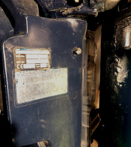 |
And now that I find this out, this bottom fitting, and my new top fitting AND the grease gun will become A LOT MORE FRIENDLY with each other, enough to force a slight amount of grease out both top and bottom shaft / bushing seals, ensuring that there is enough grease captivated inside around this shaft to grease the bushings. It will be a lot easier to wipe up any excess grease than to do this repair again. The grease I used here was molyibnium water-proof grease. Now if greased often with a good marine grease, it should provide many years of service.
| Here you see the motor being reassembled |
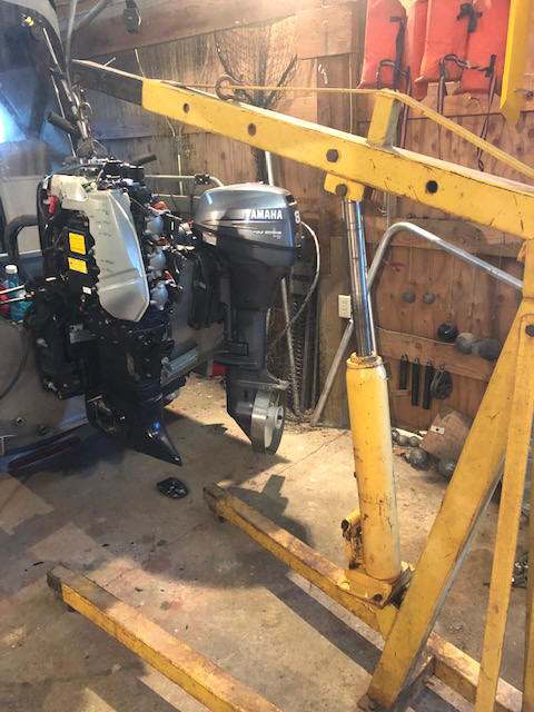 |
In the photo above, the white Ell shaped part on the motor is the oil reservoir, which was full, but didn't need to be drained using this method.
Replacement parts were ordered from www.marineengine.com, which arrived very rapidly.
Before reassembly, the steering shaft arm and upper mount area was wire wheeled to remove loose paint and rust, then painted with numerous coats of zinc phosphate primer and the matching Evinrude blue. After reassembly, any other areas in need, were also cleaned to the bare metal and repainted.
All the bolt threads involved here were
wire wheeled to remove any debris or corrosion, and coated with an anti seize compound
before reassembly. The large shaft nut was Loc-Tited with a medium
(blue) locking liquid.
In my mind, the cause of this seizure was probably four-fold, (1)
The powder coating on the shaft at both seal failed, letting saltwater to enter the
seal/shaft/bushing areas. (2) My extended non usage at the
wrong timing. (3) Right after I identified this seizure, I drilled and
tapped the upper bushing area and installed a Zerk grease fitting, but
greasing it did not help as it seemed impossible to force any grease in. What I then found during this final repair, was that the
upper Nylon bushing was seized ONTO the shaft (lack of full lubrication) and it was rotating
(or trying to) inside the
steering housing bracket, adding to the excessive effort for the steering
because it (the bushing) was originally pressed into the housing. (4) The broken
upper motor mount was one of those things that was not an issue until I tried
to remove them, but was probably the most challenging and could have been
disastrous if it had not broke, because at that point I was not familiar with
how they functioned until later.
I had almost as much trouble reassembling the lower
unit to the midsection as some of the other issues. It seems that one of
the things was the water tube was slightly non concentric with the hole in the
lower midsection, contributing for misalignment, (needing 3 hands and a long
screwdriver to accomplish this feat). For those of you who have never
replaced a lower unit, it seems the larger the motor the more trouble
is involved. And where the driveshaft splines need to
fit the splined crankshaft pocket, the water tube and shifting rod all pretty much at
the same time all in a area where you can not see. Maybe if I gave her a
rest with a cup of coffee, she might be more cooperative.
Then
more issues popped up in getting the lower cowlings in proper place.
Maybe if I had taken all the control cables completely off, that may have
eased the problem a bit, but this took help from a neighbor to finally get them
aligned and screwed on.
Below, using the cherry picker, sure helps in trying to align and reassemble the lower unit to the motor. Here it is being held back about 1" by straps because the water tube to the water pump was not being cooperative in aligning.
| Here you see using the cherry picker to hold the lower unit in place as it is being aligned to the motor |
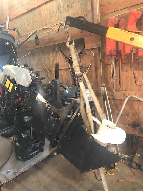 |
I will say that disregarding the many unexpected issues, this project went unreasonably well, but unplanned at times, (however with a lot of frustration along the way) even for this 84 year old shade tree mechanic. It took longer than I had hoped, as with my COPD issues, and recuperating from a heart procedure, I had to do it with numerous rest periods, along with it being during the colder January weather, broken up with short efforts of pruning old apple trees, all of which accounted for numerous hot chocolate rest breaks. Actually the tree pruning was probably about equal as to being the prime object, with the motor repair adding to the rest times. And I was able to do everything without assistance from friends or neighbors (stubborn me) up until the very last of installing the two lower cowling panels.
One thing that I think should be mandatory for any design engineer, is that they should have to work on their brain child after it has been used / abused. AND to create a well written Owners Manual. Here I saw some invocative untested ideas that down the road became of questionable value. And here, I saw first hand many new ideas as this motor was 2nd year of production of these E-Tec fuel injected 2 stroke motors. Don't get me wrong, I really like this motor, it's just different and if the Owners and Service Manuals were more explanatory, that may have helped considerably. But I suspect they (Bombardier) did not consider the owners doing their own repairs, but would take it to their dealers for servicing AND repairs.
Cost of replacing all the parts came to right at $210.00, three rattle cans of paint another $35, plus the $30 welding job. I probably could have just cleaned things up on some and reassembled them, but considering the hassle involved getting this motor torn down, it was probably a better deal in the long run by replacing all the parts. And one heck of a lot cheaper than taking it to a marine mechanic at $100 an hour labor, and you would not be reading this article now.
At least a better peace of mind now, knowing that it will now last my lifetime, and whoever owns it after me, now has as good (if not better) a repair as possible, and was the best that I could do, considering.
And now with this repair complete, with the motor not attached to the steering cable yet, a 2 year old child could turn this motor.
Old Fuel ; Now what do I do as far as old fuel in the boat's tank? Remember I cut my fishing short 5 1/2 years before, (but did one trip a year after that) so I was not sure just how much gas was still in the 35 gallon long flat tank that is under the floor, (and the gauges never read good on lower readings for these long tanks). OK, now is the time to pull the fuel tank sender gauge at the rear of the tank, jack up the front of the boat and use that to access the tank to pump it as dry as I can. And also drain and refill the 3 gallon spare tank that is under the shelf on the Port rear splash well.
And since it has been sitting for so long, I found all the top snaps and zippers need attention. Then maybe I had also better clean and re-wax the hull. Just what did I start here, looks like lots of catch up time??
More Problems ; OK, now I have both motors running, the boat washed down and a half a tank of fuel, getting ready, but now I discovered that the steering cable was broke inside the motor tube housing on the motor end. It (the seized motor issue) must have been so hard to move the motor that it worked OK pushing the cable, but trying to pull the motor back with the cable, proved too much and it pulled apart at the connection inside of the flex cable and the rear solid rod that connects to the motor.
Again with the help of the cherry picker hoist, the motor was removed from the boat, as the cable was so stiff that it could not be removed or replaced without removing the motor from the transom.
I had hoped that it was just pulled off
at the outer end and that I may be able to repair it. NO SUCH LUCK. The
rack and pinion gearbox is still OK, so I JUST need a new cable unit. But
pulling it out of the Starboard gunnel channel will not be fun, much less
getting the new one back in.
This proved as suspected. I
removed the cable retainer bolt on the steering gearbox, and clipped (cut) as many zip ties
that I could find up under the gunnel that were holding many electrical wires
onto this cable (for support). I then pulled the cable out about 2'. Then
I got my neighbor and his electrical fish tape, which he attached SECURELY to
the front end of this cable/spring. We then began pulling the
cable out from under the gunnel, but numerous hold ups, most being more zip ties that I had missed.
Finally WE got it out, (me pulling and him chasing the end coupler for obstructions). The good part, we now have a heavy duty fish tape to pull the new cable back in with. But the bad part, was that in all this pulling, it scuffed up the ID label on this cable to the point the cable length information was lost. OK, measure what I could, but for sure, take the old one as a sample to my marine dealer for a replacement at just over $9.45 a foot and 16' long. B.O.A.T.
Then in reassembly it again took the two of us, he to guide it (the cable) away from the gunnel cross supports and me pulling the electrical fish tape and we finally got it back in and connected to the steering wheel gearbox. Then using more than a couple of handfuls of zip-ties, I retied the electrical wires back up and onto the new steering cable (to keep them in place, and from sagging).
While the motor was off, I might as well clean and re-polish the rear of the aluminum transom where the motor was bolted on. Then wax it, caulk the motor retainer bolts and tighten things back down, (which was not an easy chore in itself) trying to align the motor bracket to the bolts coming the through the transom. And in able to get to the bottom bolt heads under the splash well, to hold using a Vise Grip pliers, so I could tighten the bracket nuts, I also needed to remove the center battery to gain access to those bolts.
When finished, I did not realize how easy the steering is now.
|
Here you see
motor removed from the transom, & the cable extended showing about a foot
of separation inside the middle of 3 tubes |
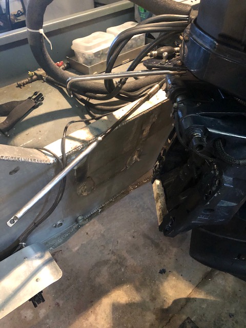 |
Another Issue ; With the motor off the boat for the above repair, I noticed a hidden zinc anode buried at the bottom of the motor transom bracket. This is not listed in the owner's manual NOR visible from anywhere other than UNDERNEATH the motor even IF you knew it was there it would be hard to identify. It is held in by two bolts, (one from each side which is about all that is visible). This anode was removed and all the oxidation removed (by placing it in a milling machine and surfacing off 1/16" on all exposed sides) before being replaced.
|
Here you see
the above mentioned zinc anode on the motor bracket, that has been cleaned, |
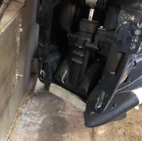 |
Then another project, as one of the
batteries is not holding a
decent charge, wonder why since they are only over10 years old. So I
replaced both with type 27 marine batteries.
Then the tires should possible be replaced also, which was accomplished.
These trailer wheel bearings are oil bath lubricated, with a threaded on
plastic see through cap. When replacing one wheel, this plastic cap got
bumped, cracking it. Looking online for replacement parts, the factory
improved their design making the threaded part out of aluminum, but with a
clear plastic center window to check the oil level. Well, I have gone
this far, might as well change them also. In replacing these, I removed
and checked the wheel
bearings, then added new grease while at it.
OK, I had the chance to take it
salmon fishing, so I ran both motors for a few minutes on muffs to be sure
things really worked. Then as a precautionary move, I took it to a local
lake for a on the water test. The main motor died in the middle of
the lake. Switching over to my small auxiliary fuel tank, I got it
running and back to the dock. I could not get the fuel primer bulb to
pump up hard, meaning that there had to be an issue in the fuel deliver from
the tank to the motor. On the way home, I topped off the 35 gallon fuel
tank.
A few years previously I have pumped all the
old fuel out, and only put in 5 gallons, just enough to run the motors
occasionally. Once I got the seized pivot shaft issue resolved, I
added another 15 gallons to the tank, as I did not know when or for how long,
that I may be using it. My initial thought was maybe that there was a
air bubble in the fuel line, so I uncoupled it from the main motor and
manually with the primer bulb got enough to squirt some fuel out. I
hooked it back up and even let it run for 10 minutes, now thinking the problem
was solved.
I had the chance for my wife's brother to drag the boat down, launch and moor it in his unoccupied berth at Chinook WA. While showing him the operation procedures, it died, (again starving for fuel).
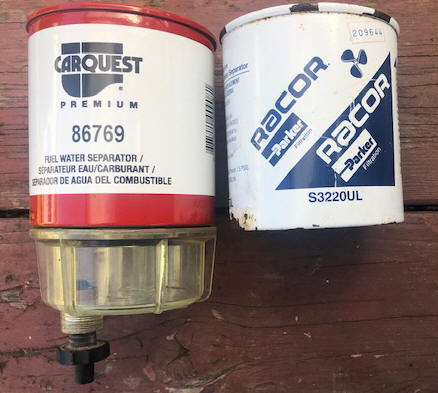
OK, time for digging deeper. The fuel line fitting from the tank was under a second battery mounting plate, so removing the battery and the plate was in order. Also behind this battery was the permanently mounted fuel / water separator. This seemed to be the most likely location to start looking as it was 11 years old. What I eventually found was on one of the lower outer edges of the canister was some rust AND this had a pin hole, allowing all the fuel in the canister to leak out into the bilge. The original filter manufacturer was Racor, but not wanting to make a 50 mile trip one way to look for a replacement, I went to my local CarQuest automotive store, which they were able to cross-reference to their brand of canister, where I could still use the see original through plastic water settling bowl. Price was not cheap, but $45 and hometown pickup, which probably was about the same (or cheaper) than making a trip to a marine dealer and then having to order it. Another option is Sierra #18-7928.
One thing to remember is to follow instructions on the canister which is to lightly oil both the rubber seals, which will greatly help later when you have to remove them.
| Here you see the original & the replacement canisters |
 |
Finally headed back on the water again
Copyright © 2021 - 2023 LeeRoy Wisner All Rights Reserved
Back to the Main Ramblings Page
Originated 01-16-2021, Last updated
02-02-2023 ***
to contact the author click here
