 |
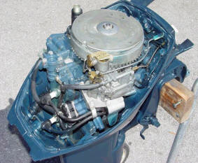
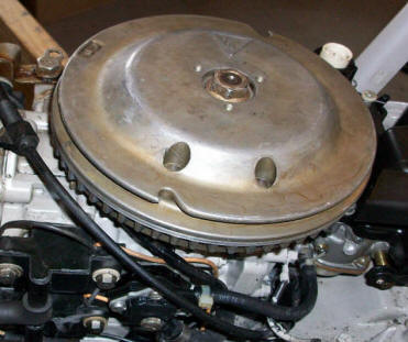
Removing the Flywheel |
|
 |
Removing the Flywheel |
|
When working on many of the older
motors, you will have to remove the flywheel to get into the ignition system.
Magneto ignition was used on
all the OMC motors up until about 1976. However some of the later
smaller motors (4hp) still have magneto ignition. The earlier models will have
coils mounted under the flywheel while some motors use external coils. Other
brands pretty well followed this pattern.
Most of us now days are
spoiled by CDI / electronic ignition on the later motors of about any
manufacturer and take it for
granted that if you have spark, the motor will run fine, and that is
correct ..... for electronic ignition.
But, for those who are new to the older engines having a magneto ignition, points are a different animal
altogether, and even though you can get spark, and the may engine run, it may not
be optimum unless the points are careful set and checked against the timing marks
on the timing plate. Failure to do so can result in poor engine performance,
a huge difference in smooth trolling idle and top end power with possible detonation under
high loads, plus poor fuel economy. OK, you may luck out on the first
try, but even a blind squirrel finds an acorn at times.
To remove the flywheel there are a few steps in the procedure to properly remove it and not ruin things. As you will usually be working on an older motor where replacing broken parts may be expensive IF you can even find the parts. Some smaller motors that utilize a built in fuel tank around the motor to be removed. Also some these may require removal of a thin metal cover which gives access to the 3 triangular positioned puller holes, mentioned in #4.
OK, Let Us Get Right With it ;
(1) Remove the flywheel nut. This should be done with a box end or socket wrench, as a 10" Crescent wrench may not be able to fir down in a recess the nut is located in OR if it does, you can round off the flats if this nut is rather tight. You may have to hold the flywheel as you try to unscrew the nut. If it will not loosen, you may need to use a strap wrench to secure the flywheel as you loosen it. If that fails, then you can resort to RAPPING the wrench handle sharply. A number of sharp raps will be better than a hard heavy single pull.
(2) Once the nut is loose, the simplest shade-tree mechanic method is to loosen the nut a couple of threads, or enough so that the top of the nut is just above the crankshaft threads.
(3) Using a large brass hammer, (2-3 lbs), wrap your arm around the flywheel, lifting the motor enough so that you are supporting most of the motor's weight tight against your body (THIS IS IMPORTANT), now RAP the flywheel nut SHARPLY with this brass hammer (no love pats here). Usually you only need to hit it once, however if it is stubborn you may need to hit it 2-3 times. What usually happens the sharp rap on the nut along with the weight of the motor, drives the motor/crankshaft down slightly, leaving the flywheel where you are holding it, and will pop it off the crankshaft taper, allowing you to then remove the nut and lift the flywheel off. DO NOT try this without the lifting, as you may damage internal parts.
| Popping the flywheel off, notice the nut is above the height of the crankshaft threads |
|
|
Keeping the nut close to even or slightly above the top of the threaded crankshaft prevents you from ruining both the nut and the crankshaft threads. If you do ruin the nut, they are replaceable, as compared to repairing a damaged crankshaft thread. You could use a regular machinist hammer but the chances are greater with a steel hammer of ruining either the nut or shaft as compared to using a brass hammer.
(4) If this does not do the job, then you will need to procure a flywheel puller. Remove the nut completely. There will usually be 3 small screw holes spaced evenly around the top of the flywheel. These will be to mount a puller to. The puller shown below is one that I made that is somewhat universal for these size of motors as the 3 bolt holes are slotted to accommodate different hole patterns. It is possible to use a 3 armed gear puller if you can get 3 hardened bolts the size of these flywheel holes, (usually 1/4" on the small American made motors). Place the puller's hooks under the heads of these 3 bolts that you have screwed in equal distance.
CAUTION -- Just because there are 3 equally spaced threaded holes in the top of these flywheels, DO NOT THINK THAT THEY ARE TO BE USED BY RUNNING THREADED BOLTS ALL THE WAY DOWN AND USED AS A JACK AGAINST SOMETHING UNDERNEATH. If you do, it is GUARANTEED you will ruin some of the components under the flywheel. And if this is a older magneto system, it may be expensive to replace some of these old obsolete parts. OK some systems may use a jack type puller, where you screw the bolt in to separate the inner hub from the outer, you will usually see them used on large shaft mounted pulleys but I have never seen any used on outboard motors (however I have heard of one, hence the caution).
In using puller, tighten down the three small outer bolts tight, or at least evenly, then tighten the large center bolt, tighten a bit more until you add a fair bit of tension on, then RAP the puller's bolt head sharply with a large hammer. If that does not pop it off, tighten again and another rap.
In all my years of outboard mechanicing these motors, I have only had to use a gear puller three times.
(5) Lift the flywheel of, while being watchful of the flywheel/crankshaft key that locates the flywheel in the proper rotation which keeps it there once the nut is tightened down.
| Flywheel still in place & the nut holding it there | Using a flywheel puller designed for this operation |
 |
|
If you don't have access to a commercial puller, shown in
the photo below is a method that works.
| Redneck flywheel puller |
 |
You will note in the photo below that this old motor has had the flywheel nut rusted to the crankshaft, the owner who lived near saltwater allowed this motor to set outside for a number of years. When he tried to remove the flywheel he did not realize it was rusted TIGHT and twisted off the threaded end of the crankshaft. Now he is hopeful that I can weld a new threaded end back onto the crankshaft. ??? !!!! He was thoughtful enough to save the broken parts. This is a old Elgin of a vintage of about 1955 which has the fuel tank around the flywheel.
| Rusted nut & shaft after being twisted off |
|
|
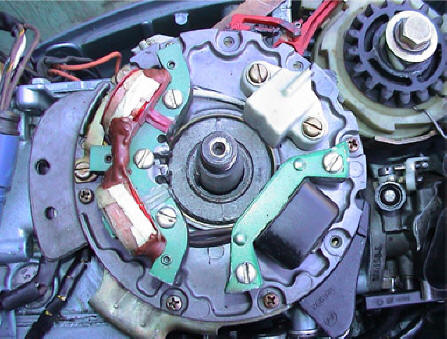
When you get the flywheel off, for older the magneto ignition motors, the same basic things will be there, but depending on the make, vintage and size of the motor, you could see different things.
Typically there will be a coil and condenser and a set of adjustable points for each cylinder (the condenser being the smaller round unit with one wire coming out of it). The electric current is generated from a magnet mounted inside the flywheel
In the photos below of magneto ignition motors, you will notice the Elgin on the left is a single cylinder motor, using one coil. The center is a twin cylinder using a coil for each. Then there is the photo on the right which uses one charging coil which powers 2 sets of points for this twin cylinder motor, but it sends power to individual externally coils mounted outside the flywheel that are mounted on the side of the block.
The points are opened are closed mechanically off a crankshaft mounted cam that is located, usually be the flywheel key. The rub bar of the points contacting this cam will open and close the points. Points are set at either a mark in the cam or at the highest position of the cam.
All wires need to be positioned so they do not rub on the rotating flywheel, free and not shorting out (other than when designed to be grounded). Some condensers will be mounted horizontal while others may be vertical. The coils need to be free of cracks in the outer insulation.
The RH photo is for a 9.9/15hp OMC that uses a driver coil under the flywheel and two individual external mounted coils (one for each cylinder). The screwdriver is shown in the adjustment slot, adjusting one set of points.
| Ignition for 1947 2hp Elgin single cylinder | Ignition typically for 1968-1976 OMC 6-18hp | Ignition for 1974-76 OMC 9.9/15hp |
|
|
|
|
For a link to how to adjust the points on the old magnetos systems CLICK HERE.
The later motors will usually have CD (Capacitor Discharge) type ignition which does away with the older points style system. Some swear by this system, while other swear at it. The beauty of this system there is never any points to get corroded or out of adjustment and the spark is considerably hotter, making for easier starting. The bad part these motors require a Power Pack to transfer a high voltage to the outside mounted coils which then transfer it to that spark plugs where it does fail at times, which is considerably a higher price than internal/external coils or condensers.
| This electronics is for a 1982 OMC that shows the pickup sensor, primary coil & the 2 charging coils for the electric start unit |
 |
For those who are interested here is a link to the theory of operation of 2 cycle outboard motors CLICK HERE
Copyright © 2012 - 2020 LeeRoy Wisner All Rights Reserved
Back to the Main Ramblings
Page
Originally stated 05-10-2012, Last Updated 11-29-2020
Contact the author