|
Outfitting a 50+ Year Old 12' Aluminum Lake Boat / Trailer & Doing it Economically
|
 |
One of my
later
boat/trailer endeavors (and probably my last) at age
84, is a old 12' aluminum StarCraft Sea Scamp. From
the hull ID markings, it was made in1968. This boat came without a trailer, as in
it's previous life, it probably spent a lot of the time in the water,
or upside down on the shore of a freshwater local lake.
This boat was in surprisingly good shape for being as old as it is. The inner paint is original, and only worn on the floor. Very few minor dents or scrapes are visible. This boat's hull rivets are surprisingly solid, indicating (to me at least) that this boat was not abused. The only real issue was the plywood transom had deteriorated to the point that it was almost totally non-existent because of rot, and partly obliterating the ID plate that was just a decal attached to this wood. Therefore I saved the info off this plate, and reconstructed a new aluminum plate that was screwed in place on the inside of the new transom, thereby satisfying any DOL or possible law enforcement inspection.
This boat is rated at 3 persons or 500# and with a engine's maximum horsepower of 10hp.
There is no drain plug,
so my guess is that somewhere in it's lifetime, it sat on the shore,
sometime in it's previous life it probably sat in a upright
position full of rainwater for extended periods of
time, and being here in the Pacific Northwest,
conducive to the rot. To rectify this
situation here in Washington State (where it rains a
lot), I installed a new drain tube. Here I had
previously made a drain tube flaring tool, that
after drilling a 1" hole in the transom, insert a
new tube with 1/2" of Nylon spacer, measure enough for flaring, cut it off,
caulk it well and flare it in place. The floatation
foam under the 3 seats appear to be in very good
shape.
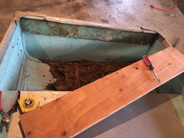
Boat Repairs ; In replacing this inner rotted transom, I laminated (glued and clamped) 2 sheets of 3/4" plywood and made them 2" deeper than the original, giving a bit more transom support. In order to fit this new transom inside the aluminum's hull, I had to drill out the bolts and rivets holding one (the RH) cast aluminum corner brace/handle to be able to precisely fit the new plywood snuggly up and inside. Then I just bolted this brace back on using stainless steel machine screws. I also installed a new 1/2" plywood motor mount pad on the rear outside of the aluminum transom.
| Shown here is the start of repairing the rotted transom. NOTICE all the rotted wood pieces that was once the transom support laying in the bottom & the new unfitted plywood that is laying on the cross seat |
 |
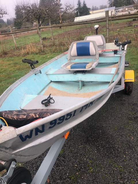
Seats ; Just setting on those hard aluminum bench seats for any length of time don't cut it for lot of us. Versatility and maybe some comfort are the name of the game here. However on a boat of this size you do not have many options. Here, in doing this job economically, I used some used seats (both front and rear) off another project. I fashioned a non permanent, movable, but secure mounting system that simply clamps an 1/8" X 2" metal strap adapter plate onto the upper edges of the existing sheet aluminum bench seats.
After the first shake down run (with me doing it solo) I found that my initial thoughts of placing the seats on opposite sides to distribute the weight when 2 persons were aboard, may have had some merit. BUT with only me aboard (weighing 250#), AND with the low freeboard of this boat, it was quite an awakening (if I leaned to far outward) only to see lots of water pouring over the gunnel at the transom. It became very apparent very quickly that I needed to replace the hex nuts on the underside seat clamps with wing nuts, so that the rear seat could be readily adjusted toward the center for better balance under these conditions.
| Shown here is the boat outfitted with seats and electric trolling motor |
 |
Storage Space ; There is not a lot of room in/on boats this size for storage of about anything. Here I added a Harbor Freight plastic 30 caliber ammo box providing waterproof storage on each side, behind the rear bench seat and against the inside of the outer hull, (on both sides) securing them with 9" ball Bungee cords. These hold safety equipment (flares, emergency tools and parts).
In securing these plastic ammo boxes, numerous ideas were tried to attach the bungee cords. The rear location for the bungee was simply to run the cord through the eye of a screw eye that was attached to the bottom of the transom's plywood. But finding a good location for the front hook at the seat proved to be a problem.
First, I just drilled a small hole in the outer upper cross seat flange and placed a small "S" hook. This location proved to be too high and tipped the box upward in front. Plan B was to use a screw hook at a lower location into the back face of the rear cross seat. This also proved not doable as the cross seat metal was so thin that it would not hold that screw well. Plan C was to then drill and tap this area to a 10-24 threads and use a short 3/16" eye bolt that part of the eye was removed to form a hook. That also failed again, because of the thin metal. Plan D was finally to J-B Weld a 1 1/2' X 2 1/2" band aid type 3/16" aluminum patch onto this rear face in the location that was previously tried. To hold this patch in place until the epoxy cured, strapping tape was used. Then drill and tap the patch, and use the previously made threaded hook, using a nut on the shaft as a jam nut to keep the hook in position.
Sonar ; Here, I opted to at least for the time being to not go with sonar. For years we have fished without this device, and as my memory is still somewhat, we usually did pretty good at catching.
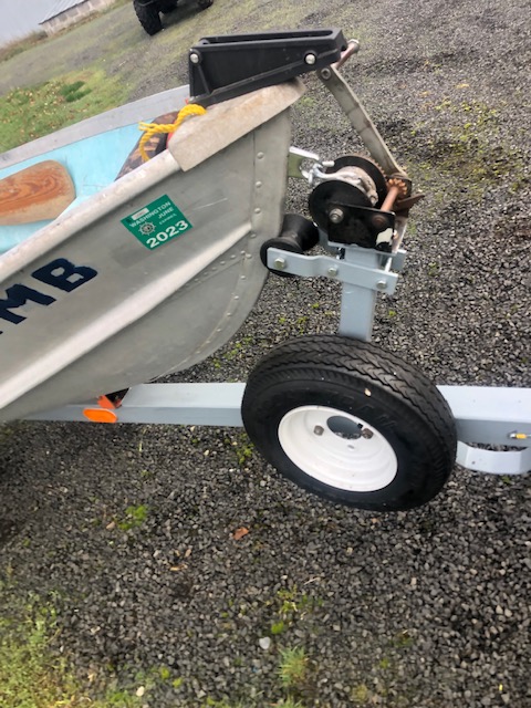
Bow Eye ; There was none here originally, only a grasping hole in the cast aluminum bow nose, (as seen in the photo below). Since I am going to trailer this little jewel, I needed to install a good solid eye through the bow to attach the winch rope hook to, in order to secure the boat's bow onto the trailer. Along with this, a light chain/hook was used as a boat safety chain. Here you also see the anchor line chock and spare tire.
| Shown here is boat bow eye and trailer winch |
 |
Propulsion
;
Here, my plan is to use a 1952 2hp air cooled
Elgin outboard motor that I had recently
restored. And upon testing it on this boat, it ran
fine, and pretty well fit for the needs that this boat
is capable of.
Also this boat's main purpose will be used as a test project for the dozen
small, old restored to running condition outboard
motors that I have worked on. For a link
to those articles
CLICK HERE.
And IF I will be using it on a impoundment or lake where internal combustion type motors are restricted, then my Minn-Kota 44# thrust, 12 volt electric motor will be used, and of course then a large marine type battery.
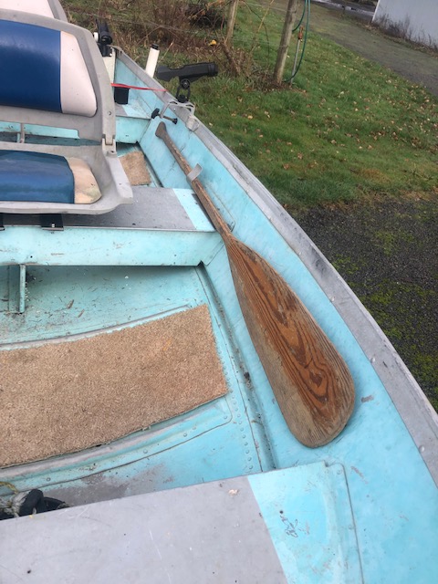
Currently, as an emergency propulsion, I have added a used 5 1/2' paddle, that is mounted on the Port inside of the gunnel between it and the front swivel seat. It is simply held in place by one upward protruding aluminum strap, that is pop riveted to the rear of the middle cross seat. With the slight arcing of the side of the boat and this retainer strap pulling the paddle tight against the inside of the hull, it puts enough tension for the paddle to be secure but yet readily available.
| Shown here is the front folding seat, carpet, and the paddle |
 |
However I do foresee replacing this paddle with two piece aluminum oars in the future.
In
the photos below, you see the skipper's fold seat,
rod holder and waterproof storage box. Also
the roller loading guides on the trailer. On
the left you see this boat outfitted with the 2hp
restored Elgin. On the right, it is shown with
the electric trolling motor.
| Shown here the propulsion is a restored 1952 2 hp air cooled Elgin outboard motor | Shown here the propulsion is a 12 volt electric trolling motor |
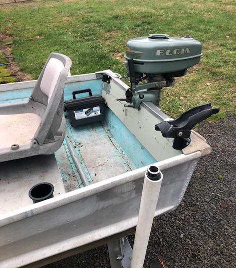 |
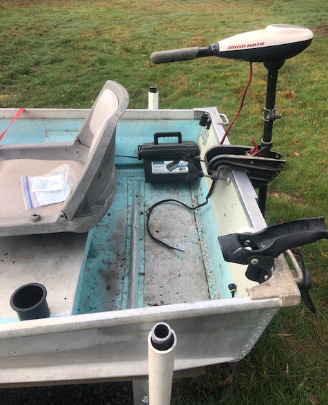 |
Carpet ;
Here, the floor cross ribs in the bottom of this boat are 13" apart. I
used an old close knit carpet from a bedroom
remodel, that was cut to simply lay between
these ribs as seen in the above photo. However
after the first test run, when I leaned over too far
and shipped some water from over the rear gunnel, so it became apparent that the
rear two sections needed to be removed, as it made
for a lot easier bailing water out without the
carpet there. And really did not need it there
anyway.
Bailing Device ; Here, there is no room, nor real need for a bilge pump, but some source to bail out rainwater. My experience in small flat bottomed boats like this, is that if you purchase a flat bottomed pet/cattle feed scoop, you can usually bail out rainwater quite easily. Round buckets do not work here. And with the carpet just laying on the floor, they can be removed of need be for a more complete bailing.
Then as a backup, a trip to Ace Hardware and for $3.95, I came home with a synthetic sponge 2 1/2" x 4 1/2" x 7" which does quite well once the bulk of the water has been removed.
Rod Holders ; I have used Fish-On brand rod holders for years, so do have a few of these spare holder bases that I mounted on the inside corners of the transom. For the side locations that would be desirable for 2 people fishing, I again used the same rod holders mounted in custom made aluminum base brackets.
Cup
Holders ;
Here, again I had some left over cup holders that I mounted on the
bench seats.
Anchor ; Anchors for this size a boat can be just a simple old large tin coffee can (if you can find them anymore) filled with concrete, or a 8 to 10# mushroom anchor being the most common. However, again to be economical, I used a 8# mushroom anchor and rope off another project.
The Trailer ; Initially, I loaded this boat in the back of my 1/2 ton Ford pickup for the ride home, but at my age (84) and I fish alone a lot of the time, where when at the bottom of a ramp, unloading and launching or to reload the boat from/into the pickup bed, then transfer the motor and all my gear into the boat, I am afraid that along with me holding up the launch area for other boaters, AND that I would be out of breath because of my COPD that I possibly get discouraged before too long.
This then demanded a trailer. On my limited fixed retirement income, purchasing a new trailer was not in the cards. Therefore in making this trailer, I used a lot of used metal parts that came from my scrap pile, left over other boat trailer projects, or even purchased at a yard sale, other than the new main frame metal tubing, and bolts/nut that I did purchase.
In doing internet searching, I found a photos of factory trailers in the size that I was fitting this boat to. Using this as a guide, and from my sketches, my neighbor who is a welder/fabricator, welded the main frame and tongue. My days of welding are long gone because of Macular Degeneration in my only eye (I can still tack weld parts together (of sorts), but not the final welding).
Here, I might also say that being a retired machinist, I still have a pretty full operational machine shop.
The axle/frame/springs unit came with12" tires/wheels and was purchased for $30 at a yard sale a year ago. These tires and wheels had been used to upgrade on another trailer project, but new 8" tires and wheels off that trailer were used here. The 8" metal fenders off the earlier upgraded trailer were also fitted to this new one.
The used winch was picked up up somewhere, but my memory of when/where, is blank on this one. Bunk supports being 1/4" X 1 1/2 X 1 1/2" aluminum angle from a long ago abandoned bracket/frame for a 75 quart cooler removed from off the extended transom of a older larger boat that I had at one time, where the metal was now salvaged with enough to make these supports. This material being aluminum, made it easier to work with, which the lower support part having a 1/2" slot milled in them to provide for vertical adjustment of the bunks. These bunks are 2"X4" fir lumber, covered with an old short, tight woven carpet, that was stapled onto the underside of the 2X4s.
Now to figure out the locations of the keel rollers and side bunks, along with the location of the axle frame, I secured 3 ratchet straps to the upper floor beams of my barn, then down to the corners of the boat. By lifting the boat horizontally and backing the partly completed trailer under the boat, I could easily ascertain the needed locations of these parts.
Here, all the parts are bolted onto the frame other than the mid rear cross bar, which was welded on. After setting the boat onto the rollers and bunks, AND adding my outboard motor, along with the fuel tank, battery and other heavy gear into the boat, I then could determine the location to position where the axle/spring unit needed to be positioned under the trailer frame for balance and tongue weight, then C clamped this axle/spring unit in place, where it was later welded onto the frame.
As a note on price for these center keel rollers, I originally purchased 3, but later decided that I needed another 2 more, not to support the weight, but for better guidance when loading the boat. The local marine dealer (US Marine in Olympia WA) was closed on Mondays (the day I made the second trip there), so I went on to Cabelas. WOW, sticker shock as to their price. My original rollers cost $7.49 each, Cabelas price was $13.99, --- NO, AT THAT PRICE, I CAN WAIT ---
In the trailer photo below, there needs to be another cross bar welded between the 2 front/rear ends to provide for another keel roller, along with 2 more rollers forward of the forward one shown. These keel support rollers may not be needed for support, but more for boat alignment when loading from a launch. And as seen here, the axle position has not yet been determined.
The fender angle brackets were welded to the frame and the fenders were then bolted to front and rear brackets as a final detail.
The tongue was initially made longer than needed, since I did not know my balance point, nor just where the boat would finally sit on this trailer. Now after the winch mount support was installed, the tongue was cut to length and the ball hitch welded in place, along with welding the safety chains in place.
| Here
is the trailer is part way finished, showing the positions of the rollers & bunk pad supports. |
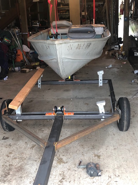 |
Boat Tie Down ; With the boat setting on the trailer, in finishing the trailer, we welded a large chain link on top of each side of the frame slightly rearward of the axle, as an anchor point to use a ratchet strap tie down for the rear of the boat.
| Here is the boat rear tie down in use |
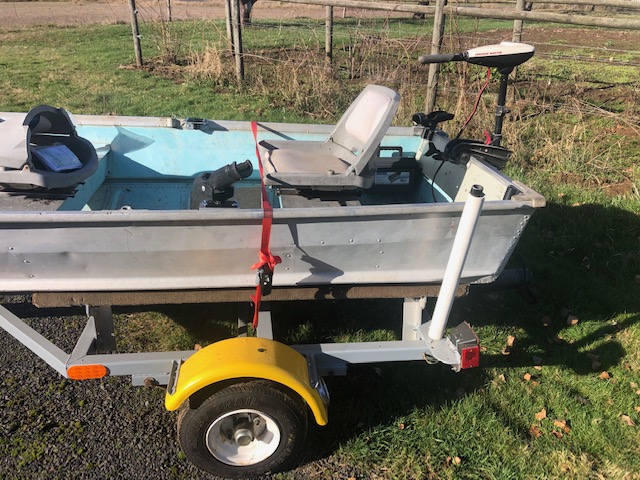 |
Bunk Loading Guides; With this boat being narrow and very flat bottomed, I felt the need to install some rear bunk loading guide rollers, (which have later proved their worth). I have seen, AND had my own share of boats that at times break their training rules to not be anywhere near being aligned on the trailer rollers/bunks during loading, (ESPECIALLY IF IT IS WINDY, OR A CURRENT IS RUNNING). Here, I fashioned from 1" double strength steel pipe as a support and by slipping a 1 1/2" PVC pipe over the steel pipe, creating a sloppy fit PVC roller. This pipe was welded onto a 2" X 3" steel angle that was bolted onto the outer rear of the trailer frame, which also provides support/attachment location for the lights and license plate. 1" pipe caps were bored out on the metal lather to allow them to just slip fit on top of the 1" protruding pipe above the PVC roller. These caps are secured by Allen type set screws with wing nuts welded onto for a no wrench leverage.
| Here
the trailer is finished, (minus the painting) showing the positions of the keel rollers, bunk pad supports, loading guides and the divers flags. |
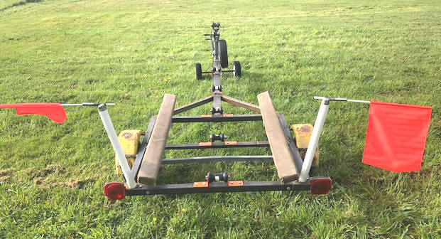 |
Not Being Able to See These Narrow Trailers; How about not being able to see a trailer especially when it is unloaded, (only 5' wide) when backing down the launch for recovery ?? The photo above illustrates my solution to this issue. Here I welded a 5/8" steel tubing (1/2" would have been better, but that is what I had) at a slight upward angle to the guide bunk caps that is then secured to the top of loading guide pipe with a 5/16" set screw. Here I can stick in cheap divers flags that protrude outward and slightly upward, allowing me to easily see the trailer's location in the vehicle's mirrors.
To prevent these from falling out during the launch/recovery process, I found some 3/8" ID X 5/8" OD rubber grommets that just slip snuggly on the flag shafts. These flag shafts are fiberglass and are slightly oversize 3/8", allowing for this snug fit. Two grommets on each shaft, one outboard of the tubing to keep it (the flag) from sliding inward, AND the other on the lower end to keep the flag from coming out. The outer one will stay in position, but the lower one can easily slid off/(back on) to remove the flags for traveling.
The main thing to remember here is after launch time, to remove these flags from the trailer and not place them in the boat, but place them in the towing vehicle, to then be used when backing the empty trailer down the ramp. As it seems that invariably, I remember them after I am up the ramp and almost to the vehicle in the parking lot.
Winch ; For the winch mount, I salvaged a section of the 2" X 2" frame square tubing, cut the bottom at the proper angle and welded it to a bottom plate. This bracket was then positioned into place so the bow roller and winch cable hooked into the boat's bow eye, pulling the bow slightly down, then it (this winch mount) was then drilled and bolted onto the tongue. The bow stopper roller is mounted at it's front by a 1/2" bolt between two 1/4" x 1 1/2" steel straps which are clamped straddling the upright by 3/8" bolts (which allows for minor adjustments).
The winch itself was from a scrap pile, it was functionable, but was missing the latch dog spring, which I fashioned from some heavy duty 1/16" spring wire.
Spare Tire Mount ; The spare tire mount (as seen in the above photo) was made of 1/2" round 1018 CRS. The 4 lug wheel and tire that was left over from a previous trailer remodel (now flat tire, but we can deal with that later). Matter of fact in inspecting the tire, it was so badly checked on the sidewalls that I did not want it as a spare, and in trying to find a replacement tire, the complete tire and wheel was only $7.00 more than just the tire, so another trip to Harbor Freight.
The distance
was 3 1/2" inside measurement to the wheel lug bolt
holes, by measuring and calculating how much was
needed extended for the nuts to be there to hold the
wheel on, I cut the rod at 15 1/2", then rough lathe turned 2
1/2" length of 1/2" X 20 NF threads on each end, and
then chased them with a threading die. I
then heated the legs with my Oxy/Acetylene torch, and
bent them at 90 degrees, forming a 3 1/2" inside measurement X 6"
U bolt. The nut is the same size as the
lug bolts, for compatibility. This U bolt now
straddles and is clamped low on the
winch support, for a out of the way spare tire
mount.
The threads of this U bolt were coated lightly with
trailer wheel bearing grease to ensure the nuts will
come off if/when needed.
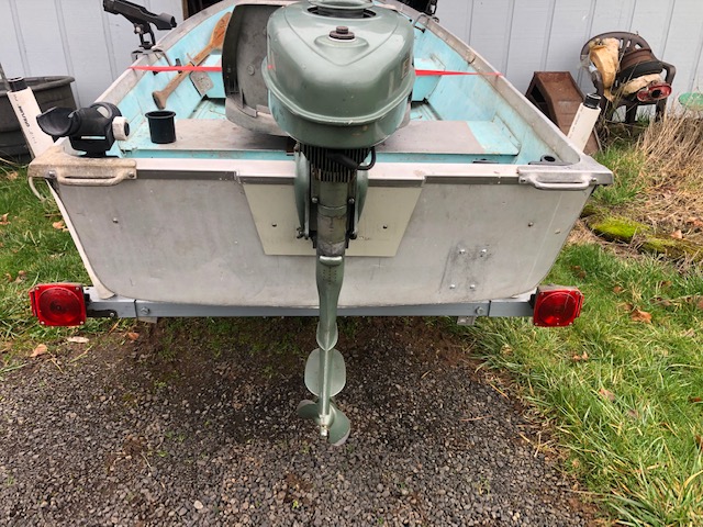
Lights ; For lights, another trip to WalMart for a cheap ($7.95 each) set of trailer lights. These are not waterproof, but upon bolting them onto the trailer mounting bracket, I caulk the inlet wire openings, and also make a lens gasket out of 1/16" sheet cork, which has proved to be quite waterproof for me on small boat trailers in the past. But for my 18' saltwater boat I use sealed lenses.
| Shown here are the lights with the boat on the trailer before it was licensed |
 |
Wiring ;
Wiring for the lights proved a bit unconventional, as my
welder friend did not read my drawings good enough, or look
far enough ahead, cutting the square tubing at 45
degree angles, then welding them in a box
type shape for the rear frame over the axle. Therefore
my plan on running the wiring down inside the
tongue, then along inside a 2" angle or channel iron
rear frame went out the window. So, either I would have to electrical
tape the wire to the frame, or secure it using
plastic "P" straps pop riveted to the inside of the
frame from the tongue rearward.
More head scratching and I finally decided to try to pull the
wire inside of the welded tubing. I was able
to easily run the wire inside the tongue to the front of
his box frame as originally designed. Then, I drilled a 9/16" hole on
the outer corners of the welded frame, ran a electrical fish tape
in and out the holes, doing a
lot of probing/fishing to find the looped end inside the
tubing, and pulled the new wire in from the front
(so there was no splices) and the molded on coupler
plug in is at the front of the tongue. The
open holes were then plugged using plastic push in plugs.
The holes that wires went through were caulked, as I
did not like the idea of having water trapped
inside.
All connections at the lights were twisted together,
soldered and then heat shrink tubing covering the splice.
The ground wire was grounded at the front being
screwed to the tongue. The lights themselves
are grounded to the frame at the rear through their
attachment bolts. The wire where it lays on
the top front of the tongue, behind the welded
on hitch was secured by a plastic P strap screwed to
the tongue.
Then the RV wire plug in pig tail was made up to match the small 4 way molded in fitting on the front of the trailer's wiring.
I did get the fenders sanded down, removing most of the existing rust, and got them repainted. On top of the fenders were 3/8" holes that originally was the anchor point for foot steps. These were plugged using 3/8" Nylon snap in plugs after the paint job.
Now just to get a few good sunny days so I can unload the boat, get the trailer pulled outside of my barn and tipped on edge, then finish painting this trailer. I finally got it done. My color scheme was to repaint the fenders again with safety yellow and the frame machinery gray, simply because that is the paint that I had on hand.
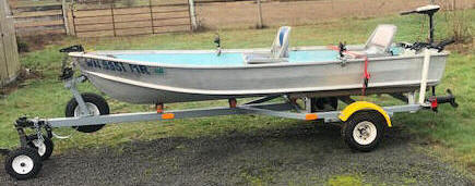
| Shown here is the final outcome of this project, with the electric trolling motor |
 |
Launching Alone ; Here you need to develop a procedure. The main thing is that you will not have someone to hold onto your bow rope as you launch. To solve this issue, I use a bow line that is long enough to allow the boat to drift off the trailer, plus a few feet, with a large loop in the loose end, which can be tethered over the winch post.
In use, after the boat floats off the trailer, slowly pull the vehicle and trailer up the ramp, just enough to convince the boat to follow you until it either stops on the ramp, or at the rear of the trailer. Then you can walk back on a dry ramp, remove the bow line from the winch post, move and tie your boat to a dock or shore.