 |
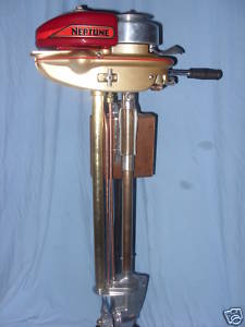
Restoration of Neptune 1.5, 1.7 & 2 hp "Mighty Mite" Outboards |
|
One thing that I want
to convey here is that I write only on motors that I have actually worked on, and
over a period of MANY years, consisting of many THOUSANDS of hours, and then
more in maintaining/updating these pages. These articles are usually motor specific,
HOWEVER if you are having a diagnosis issue, my Trouble Shooting article covers
MANY more aspects that may help you diagnose your issue.
CLICK HERE
for access to that article.
If these little motors could talk, imagine the stories they could tell, just lay back on a sunny day, close your eyes, let the world pass by and your mind wonder a bit. Kind of makes you want to take an old flat-bottomed rowboat with one of these motors on the stern, put on a old pair of jeans, a straw hat with a spear of grass in the corner of your mouth then just do a lazy day on the lake trying to drown a worm. In the years they were made, they provided lots of unhurried recreation at a modest cost.
Muncie Gear Works also under the name of Neptune, manufactured both single and twin cylinder models in HP up to 7.5 and sold to many business that resold them under their brand names. However here we will just deal this this small motor that ultimately became their Mighty Mite line.
These little motors were normally found in either a 1.2, 1.5 or 1.7hp, (same basic motor), but the 1.7 used the same piston, a different head and carburetor. The hp increased as the years/models advanced. With the final motor being 2hp. They were initially made by Muncie Gear Works (Muncie Transmissions for all you Chevy fans) and were basically cosmetically unchanged (except for carburetors) from about 1938 to 1974. Only weighing in at 17 lbs, they were great for 8' or 9' prams or 12' aluminum Jon boats. At that time, they were nicknamed by a few as "Egg Beaters".
I won't go into the history of these little motors to much, but will provide a link to what someone smarter than I and has been in the business longer, has already put it together CLICK HERE. or HERE And for a link to another couple websites that are helpful if you are restoring these motors, CLICK HERE for magneto information, or HERE for some frequently lost or broken replacement cast parts. Or HERE for replacement decals.
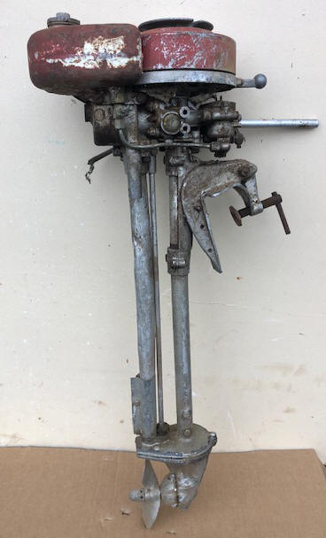
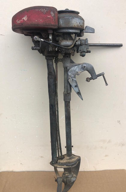
Briefly, the company started in Muncie Indiana in 1910, by 2 brothers who originally made automobile transmissions and were associated with Warner Gear Division of Borg Warner. When that market dried up after the start of the "Great Depression" in the fall of 1929, they got into the outboard motor business in 1930 and came out with a small line of inexpensive outboard motors in 1931. Then in 1938 they copied the discontinued but popular single cylinder 1.1 hp Evinrude Scout/Pal motor as seen in the LH photo below.
Notice the similarities in the photos below.
| 1938 Evinrude, ELTO Pal | 1945 Neptune Mighty Mite 15B1 |
 |
 |
All early model numbers started with "OB". They made some for the Sears Roebuck catalog under the Motor Go and Waterwitch label, but still used OB in the model number. This was in place through 1937. In 1938 they dropped the OB prefix and went to 3 or 4 numbers followed by a A, B, or C. Early on two of the numbers were the year built with the other number being the horse power of the motor. Those with an A were plane motors called Muncies. The B models were deluxe outboards called Neptunes, and the C models were built for third party for catalog sales. In 1940 the models started with 10, 1941 models started with 11.
To explain this code more, where a model 17A1 would equate to (1) only sold as a Muncie, (2) the year (1947), (A) plain motor (probably no skirts), (1) a motor less than 2 hp.
Their outboard motor production ceased during both WWII and the Korean conflict because of government contracts for war components. No motors were built from 1942 into 1945 (however possibly a few late in 1945 that were assembled from mostly pre-WWII parts). But some that were in inventory were sold as evident from a 1943 add that I have located which advertised a 11A1s (1941s). This was at that time called the the Junior Single, (which sold for $41.50) and was the forerunner of the Mighty Mite.
Powered by less than two horsepower, the portable Mighty Mite outboards would evolve over four decades of production in design adopting a strong reputation from small boat consumers.
Unfortunately, Neptune pissed-off their dealer organization back in about 1950 by offering to sell direct to the public. Sales plummeted as dealers dropped the brand, and Muncie Gears Works shut-down production of Neptunes for about 4 years. They then began selling Neptune the 1.7 hp motors under the Mighty Mite name about 1955 but only by mail order through advertisements in the likes of Life magazine, Boys Life, Popular Mechanics etc. Word was that you could earn a Mighty Mite by selling a specified number of subscriptions to magazines.
Mechanical
Description ;
The 1.2 and 1.5hp had the spark
plug protruding to the RH side of the head as witnessed by the bulge in the
side cowling of the LH header photo above. The 1.7hp had the spark
plug relocated at the center rear of the head. The early model numbers
seem to have incorporated the years into the model code. After 1952 or
so then the model numbers were different.
These motors were single cylinder water cooled 2 cycle motors. The water pump
impeller was a close fitting aluminum centrifugal pump. No thermostat was
used. The ignition was magneto type using points and condenser made by R. E. Phelon of East Longmeadow MA. Carburetors were Tillotson
of a different versions depending on vintage. There was no neutral
or shifting, and steering was approximately 270 degrees. Most all of the early motors
were bare sides, but some of the late motors used a cast aluminum side panels,
which usually indicated a deluxe model. All but
the real late motors used a wrap around rope on top of the flywheel to start the
motor with. Initially there was no choke, but a "tickler" on the top of the
carburetor to slightly flood the motor with fuel. These carburetors used a
inverted main jet attached to a cork bowl float.
The steel fuel tanks hold 2 pints which had a run time full tank 1 hour and 20 minutes (or so the factory literature says). These tanks were made in about 3 different shapes, with the early teardrop being the most popular. Later tanks were bobbed off both at the front and rear, which allowed for the motor to be stored laying up on this part of the tank. And the last was a plastic tank which was mounted under a plastic outer cowling.
Restoration Projects of 15A1, 15B1, AA1 ; A goodly number of years ago a friend offered me some of his deceased father-in-law's old Junker outboard motors just to clear out the garage. Of the lot that I picked was 3 of these little jewels. One was seized up, another had a broken clamp bracket that had been welded of sorts, the other's exhaust pipe had badly bent and beat up. All in all, initially for this project, I picked out the what appeared to be the newest, most easily repairable one for this first project, it being a model AA1, then cannibalized parts off the seized motor, which then made my chosen one somewhat complete for this restoration project. However it did have the broken skeg. These motors had sat for in a garage for probably over 25 years before I got them at least 15 years ago.
This group of engines (the 15 series, meaning 1 HP series, 1945 ) was the first to be named the MIGHTY MITE style motors, and were 1.5hp. They are easily distinguished by their spark plug, which was mounted on the starboard side of the cylinder head. With the exception of the piston and cylinder bore, almost all the parts were interchangeable within this Mighty Mite group other than the carburetion system.
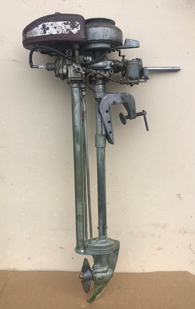
Here, I will not separate these rebuilds, but try to lump them together, because of the similarities, other than the obvious differences. In the photos below, notice the LH photo has the side mounted spark plug and no carb timing cam as compared to the RH photo showing the spark plug at the rear of the head.
| Here is a 15B1 before restoration | Here is a AA1 restored to a running condition |
 |
 |
Statistics For Both the 15A1 and 15B1s ;
For the 1.5 hp
motors @ 3000 RPM
Single
Cylinder
Bore diameter 1.562"
Stroke 1.500"
Displacement 2.87 CI
Rope starter 11/64" dia. 55"
long
Bearings, bronze bushings, both mains & rod
Tillotson carburetor #AC-1C
High speed jet, preset 1/2 to 3/4 turn out
Idle jet - none
Fuel cap. 2 pints; Run time full
tank 1-1/3 hr;
Fuel mix is Oil 2/3 pt. (12:1) SAE-40 per Gal
Point gap is .020
Spark
Plug gap .025, Champion J6C or J8J plug
Condenser -
Phelon FG-3593
Flywheel key .125" X .200" X 1.060"
Water Cooled - aluminum 4 blade centrifugal pump
Gear Ratio - 13-20
Prop. dia. & pitch 6″ X 5″ - 2 Blade, LH
Shear Pin 5/32″ X 1″, brass
Prop nut retainer pin - 3/32" cotter pin
Prop nut, brass-acorn -
7/16" NF
Weight 17#
These particular motors appear to have been built in late 1945 or early 1946 of left over Pre War parts. This one had sat for MANY years with it's sibling described above for many years. One motor was frozen up, the mount bracket had been broken and someone tried to weld the aluminum back. The rear of the gearbox where the muffler attached was broken off and patched with sheet metal. The muffler was damaged a lot and again patched with a wrap around piece of sheet metal. One fuel line was missing and shut off valve damaged. The main jet needle and it's indicator plate were missing on the other.
Before I decided to
even try to get this one running, I had to find out why it was seized.
If the piston was rusted to the cylinder, this one would have probably just
been scrapped out, but read on.
Upon
removing the fuel tank and the head, the piston was up almost to Top Dead
Center, and missing the head gasket, so someone has had it apart trying to
find why it was locked up. The top of this piston was very clean. When spraying WD40 into the cylinder and letting it set for a
while, and by rapping the top of the piston with a hammer handle, it moved down about 1/8", which was
encouraging. WOW, maybe I have another candidate for revival
here??
In making a new head gasket, I could not find any gasket material of the composition that I thought I needed. Only a 1/16" semi hard paper type material. My thought that this my not stand up as a head gasket, even for this small motor. OK, I purchased Permatex gasket maker #1, which is a hardening type, as opposed the the #2 which is non-hardening. I then made the new gasket, but smeared a coating of this #1 goop on one side, let it dry and then again on the other side. Now after a couple days it hardened up enough that I could file the outer surface down and debur the fuzz with my Dremel tool. I guess we will see how it works out. FYI, Harbor Freight sells a set of 9 hole punches, in sizes from 1/8" to 1/2" for $9.95.
Then in trying to rotate it by the flywheel, I could get it to rotate, but not a complete rotation ??? In removing the flywheel, I found a loose (unsoldered) spark plug wire from the coil, which was totally out of position and apparently was what was causing the binding into one of the flywheel magnets. I later found that the spark plug wire had tape on it where it went through the timing plate, (requiring a replacement wire) indicating that someone was trying to do some electronic troubleshooting by unsoldering that connection. With the flywheel off, underneath it was surprisingly clean as seen in the photo below.
I then positioned the spark plug wire out of the way, replaced the flywheel so that I could rotate the crankshaft, it would rotate, but it was very hard to move. Maybe bad crankshaft bearings, or froze up gearbox? So I removed the lower unit. BINGO, that seemed to be the culprit, as it was impossible to move by using the prop. The flywheel / crankshaft would now turn over, but not as easy as it should be even after removing the lower unit, and the driveshaft was solid rust. Maybe I had better pull the cylinder and crankshaft, taking a look at the main bearings, however they both are just bronze bushings.
| Here you see the top of the piston, soaking in WD40 | Here you see the loose wire protruding out to the rear, & no condenser as it is UNDER the plate |
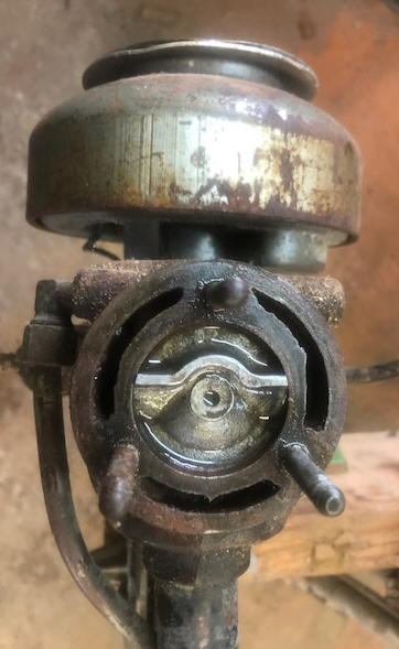 |
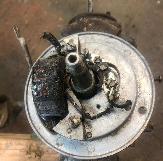 |
I then tore the powerhead apart, first the flywheel, then the timing plate, the the breaker point cam. It may be best to mark this cam as to TOP before you forget, as it appears to not have any markings on it (however this was a NON RUNNING motor and with the other internal screw ups that I later found, maybe this cam was not on right either). This plate has a tension screw underneath on the LH side, that needs to be loosened in order to lift it off the boss.
Getting it torn down to all but removing the rod so I could get the crankshaft out, it still rotated hard. Time for WD-40 on the top bronze main bearing and try to rotate it. That did it, as it seemed that the upper main bearing was dry and gummed up. And the seal had to have been inoperative, otherwise the WD-40 would not have penetrated.
Trying to rotate it still proved hard. On this motor the connecting rod screws do not come in from the bottom as the crankcase tolerance is so close the heads would hit. Therefore I could not remove the rod cap so the piston could come out the top. Then I removed the lower main bearing housing and cylinder from the block, allowing the piston to be withdrawn inward from the cylinder. Trying to loosen the rod cap screws proved fruitless as some previous IDIOT had burred them so bad, even using a 6" Crescent wrench on the flats of a good fitting screwdriver did not bulge them. Since I could not remove the connecting rod, I then removed the wrist pin clips and pushed the wrist pin out, allowing the piston to be removed, (being sure to mark it to the rod).
And I noticed that whoever tried to work on this motor before, replaced the connecting rod cap on180 degrees from it's original position (which upon manufacturing, the hole was bored and reamed to match each other). This is because the aluminum rod AND the cap both have a cast in protrusion bump to indicate their proper repositioning. After getting the cap off, the rod does not use a bronze bearing, but simply the aluminum of the rod and cap. But the interesting thing about the CAP is that it is not a smooth bearing surface, but has 3 recesses .020" deep to seemingly get better lubrication. The cap has 3 holes in it for the fuel/oil mix to lubricate into, and the rod also has 2 more holes on each side of the screw head. These cap's holes are centered in the 3 groves. The top bearing surface on the rod is smooth as it is the one that all the pressure is on at the firing stroke, and for the cap, the engine being a single cylinder the weight of the flywheel's centrifugal force helps rotate the piston back up, so minimal wear there.
The rings looked pretty good, being very clean and having lots of tension, a little rust in a couple of places, but by using 320 emery cloth backed by a piece of wood so that the edges are not rounded, I got them to where they should be very usable. Then while going this far, I might as well hone the cylinder bore also.
| Here you see the powerhead with the cylinder & lower bearing housing off | Here the block stripped down with the rod still on the crankshaft |
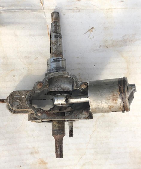 |
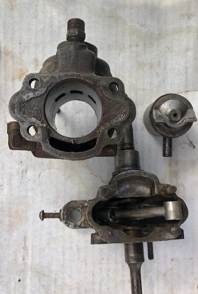 |
I finally did get the rod cap off by using a impact screwdriver (the type that you use a heavy hammer to activate). The screw head slots were really bad and hard to access with a screwdriver with the piston in place. I replaced these screws with #10 X 32 TPI (National Fine) X 1/2" long Allen head screws. However upon trying to install them, the heads were too large to fit into the recess in the rod. I therefore had to put them in my metal lathe and cut the heads down to .300" dia.
Now I have it apart enough to get crankshaft out and look into the shaft seals. I can not find any replacement seals, BUT by measuring and some experimenting, I found a Neoprene O-Ring, 7/8" OD X 5/8" ID by 3/32" wide that are not ideal, but I am sure they will work.
Also this previous DIY "mechanic" had stripped the 3 of the 4 stud bolt threads in the aluminum crankcase that holds on the lower bearing housing. Time for Heli-Coiling. And the closest studs that I found were 1 1/2" long, where I needed 1 3/16", so again my lathe was used to shorten each end by just over 1/8". These new studs are threaded NC on the inner end and NF on the outer (requiring different nuts).
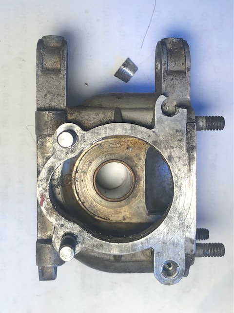
In the process of installing these Heli-Coils, on one, I accidently dropped the crankcase as I was trying to tap it oversize for the Heli-Coil. The tap was part way in the hole when it hit the concrete floor, breaking off about 1/3rd of the outside of one ear, as seen in the LH photo below.
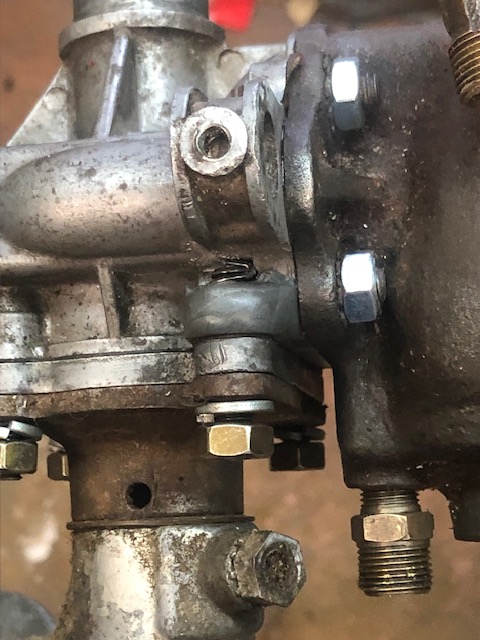
With my Macular Degeneration in my only eye, I can not see good enough anymore to Heliarc weld it back. And I did not want to waste time getting a time set with my good aluminum welder for a repair, so Plan B is now in effect. So, I cleaned the area well with Acetone, then using my Dremel tool, I ground off about 2/3rds of the metal off at the break. BJ Weld to the rescue. I gooped the break enough to stick the broken ear back on, then added more epoxy over the break. I wanted more, but was afraid to do it all at one time. A couple of days later I added more, building it up slightly more than it was originally. Then re-drill the hole the proper size and carefully tap it again.
HOWEVER, just to be on the safe side, I clamped this crankcase in a milling machine large vise, and using a spacer to match and hold the outside of this ear from breaking off again. In the LH photo below, if you ask why the other stud is missing, well when I get this broken ear finalized, I want to do a final bandsanding to be sure the surface is flat and I need the other stud missing (using that whole side of the housing as a level) to be sure I do not overdo it.
This should be strong enough as the other 3 studs are holding good, and with this Heli-Coil inside the ear, it should work out OK. I have faith in BJ Weld. The first time I was introduced to it was when a salesman showed up, and had 2 car valves BJ Welded together hear to head and he asked me to break them apart. I finally did, but it took me, (weighing 265#) at that time, by jumping on these stems simultaneously, with the heads laying on a concrete floor.
|
Here you see the broken EAR on the crankcase , with
the broken part laying there also |
Here the finished, slightly oversized, slightly rounded product in the center |
 |
 |
One change to the postwar 1.7hp motors other than moving the spark plug to the rear, was to also change the cylinder unit from a sand cast, Cast Iron to a Die Cast aluminum, and apparently with the steel liner cast into it. At this time, they also added a intake bypass cover (#4) as seen in the illustration below.
Very few parts are commercially available, however if you do need piston rings, replacement rings are available now from the company linked HERE.
| Illustrated view of the block assembly |
|
|
In examining the parts lists for these "old" motors,
the top and bottom crankshaft seals are actually called PACKING.
This may have actually been an impregnated hemp water pump type packing in
those early days.
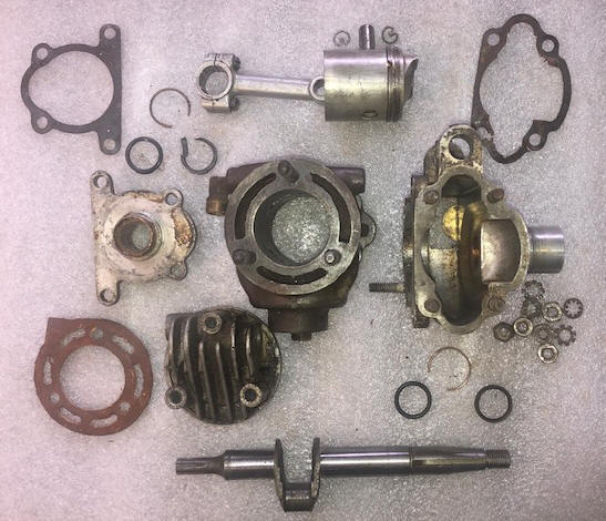
In the photo below, shown are the old shaft seals on the right with the new O-Ring seals on the left and the retainer ring above them. You will note that the original seal on the left has a broken chunk out of it, (during removal) giving an indication of how hard this rubber has deteriorated in 75 years. The seals in the photo below, the top LH ones are the lower, with the bottom RH the upper. With these seals are a wire snap ring that holds the seal in.
|
Here you see the complete powerhead torn apart & my
home grown head gasket |
 |
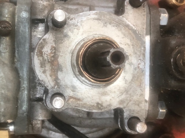
In the photo below you see the lower crankshaft bearing adapter plate and the copper wire snap ring holding in my (2) replacement Neoprene O-Rings seals. There is no real groove for that snap ring, if there is it is minimal.
| Here you see the lower bearing adapter and the snap ring bearing retainer |
 |
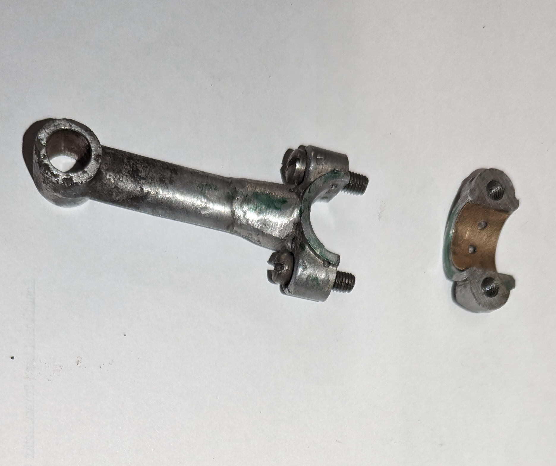
I had a reader of this article looking for a replacement connecting rod. After doing a lot of searching, he could not find one. I asked what was wrong this his, "it was broken". My suggestion was that he maybe could have it welded. I gave him the measurements off mine for overall length. Below is a photo of the finished project AND his story.
"The finished rod isn't
bad. I glued the parts to grid paper in the exact position ( about
1/16 inch between the two parts. The welder clamped the parts down,
cut away the paper and tacked it. When I put it on the crankshaft
there was a lot of slop. The CAP bearing ridges looked worn, causing
the loose fit. The crankshaft measured .620, so perhaps a bit worn?
Anyway I made a brass bushing for the cap. I found a 5/8 ID x 1" 1/16"
thick brass sleeve, cut it to fit inside the cap and then glued it to a
dowel and used the sanding disk on my bench top belt sander to take it down
to about .025 thickness. I cut it in half so that it would fit between
the two edge raised bearing ridges on the cap. I had to file the worn
ridges out of the cap, then my bushing fit snuggly in the cap. I
drilled oil holes to match those on the cap. Well no more slop anyway.
Hope it works.
|
Here you see a
readers welded/restored connecting rod & cap |
 |
Reassembly of Powerhead ; Here, we have something totally different, in that with the compactness of the crankcase, the assembly of the connecting rod to the crankshaft is rather unorthodox, because of the rod cap screws being inserted from the "top". To assemble it, the piston needs to NOT have the wrist pin installed until after the rod cap is on and tightened from the normal OPPOSITE DIRECTION, (the piston side).
Reassemble piston into the cylinder unit. (1) The wrist pin keeper rings and the wrist pin need to be removed from the piston. (2) install the rings onto the piston, NOTE that there is a protrusion on the bottom of both ring grooves that retain the rings from getting out of position and rotate into the intake/exhaust openings in the cylinder wall. (3) Install the piston into the bottom side of the cylinder. It is slightly chamfered to better allow the rings to be compressed enough to slide into the cylinder. (4) Push the piston in just far enough so that the wrist pin hole in the piston is just showing.
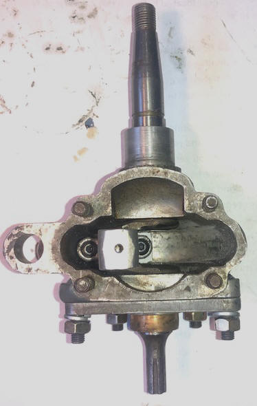
Reassemble Crankshaft unit. (1) Lightly lubricate all the bearing surfaces. (2) install the crankshaft into the crankcase/upper bearing housing. (3) Temporarily install the lower bearing housing onto the crankcase. (4) install the rod cap screws in the rod. (5) Insert the rod cap onto the crankshaft, from the open top area, (make note of the indicator ID bumps so you can get it and the rod matching), holding it in place with your finger or wooden stick through the carb intake opening. (6) If you are using the original slotted screws tighten one part way and then the other. (6A) If you are using Allen head screws, use a 1/8" long arm Allen wrench to tighten both as much as possible. (7) Rotating the crankshaft and rod to where it comes up to where you can now use the short arm of the Allen wrench to do the final tightening.
| Here, looking directly down on the rod (past the wrist pin ), you see the Allen head screws that hold the rod cap onto the crankshaft |
 |
Final Reassembly of
Connecting Rod Wrist Pin. (1)
Install the gasket on the 4 studs between the cylinder and the crankcase.
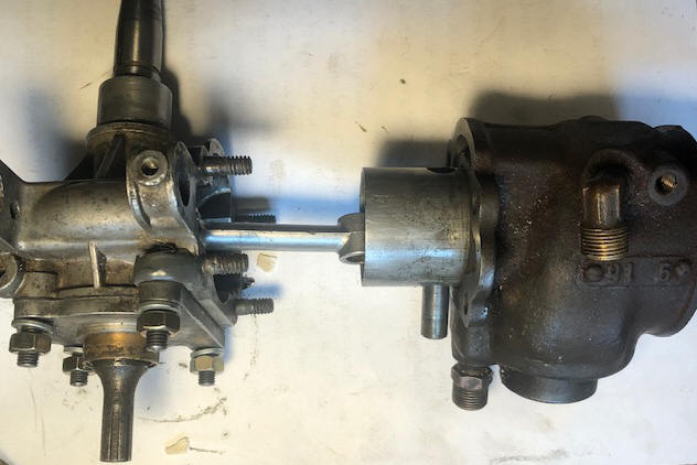
(2) As shown in the photo below, position both the crankcase unit and
the cylinder/piston so the wrist pin can be pressed/tapped into the piston.
Note, there is very little clearance inside the piston, so to do the initial
guidance, the wrist pin can only protrude maybe .020". (3)
Once you feel the rod aligned, tap the pin lightly until it is fully
started. (4) When fully inserted, both sides should be
about equal and enough to install the wrist pin keeper rings. (5)
Slide the cylinder in to meet the crankcase and install the 4 star type lock
washers and 4 nuts.
You are now ready to remove
the lightly tightened lower bearing housing nuts, place this unit on top of
the steering column bracket and tighten those bolts for final.
| Here the parts pretty well aligned, next will be aligning/pressing the wrist pin into/thru the rod |
 |
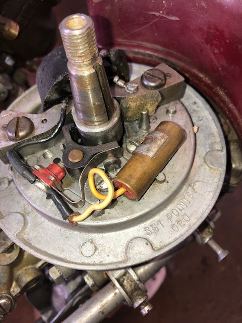
Time now to clean up the points, replace the spark plug wire and solder it into the coil lug, and remember which way the breaker cam bushing goes back on, as there is no marking on it. But to be sure, I tore apart a running AA1 to compare. This cam has a slight bevel on the top outside, with the bottom flat and not machined with finess. In the photo below note the keyway at a 3 O'clock position (looking from the front) and the points breaker arm at the low spot on the cam. This is not where you set the points at, but as a reference location for proper installation of the cam.
| Here, you can see the AA1 timing plate, including the point cam on the upper part of the crankshaft |
 |
I did later pull the gearbox cover off, and the gears were fine, it seems that the driveshaft in the bearing housing below the water pump was where it was 98% seized. But this lower unit had broken parts, but I had found another complete unit online for $42, so there was no need to proceed farther with it. Update -- after I found this, and by the time I ordered it, someone else had bought it. So back to square one. This gearbox had the rear muffler base flange broken off, that had been repaired many years ago by soldering a piece of tin can to the muffler and then bolting it onto the flange.
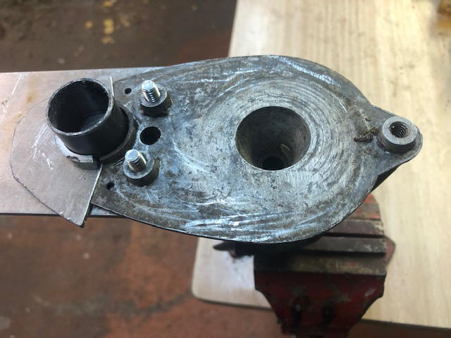
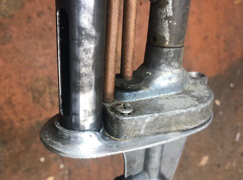
In the LH photo below, you can see my welding fixture bolted onto the underside of the gearbox, (utilizing the existing water pump's housing mount threaded holes). There also needed to be a 1/4" high rear retainer ridge which I formed from the same material, around a short section of the 1" steel muffler (as shown). Here you can see the two small holes that the tin can repair was attached to this unit by. This material will be re-contoured to match an existing motor's configuration after the welding, as seen in the RH photo. Also seen in the RH photo is the new muffler with it's exhaust slot in the rear.
| Here, you can see the new material assembled onto my welding jig which is mounted underneath. | Here, you can see the welded/restored rear section as shown on the left |
 |
 |
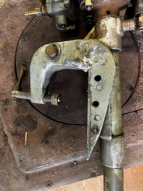
This motor also had a badly damaged/broken mounting clamp (more properly called a stern bracket in the parts list). This one had been bird-shit welded aluminum at one time (it has the appearance of a stick aluminum arc weld), along with the clamp screw threads being stripped. This unit was replaced in a trade, from one of the AOMC members scrap pile. However he gave the whole drive shaft housing (named lower motor leg) and clamp. In trying to exchange this onto my motor, I found that his was 3/4" longer (20.375" OAL as compared to mine at 19.625"). At this point I have not confirmed what motor it came off of, if he even knows.
| Here, you can see the old broken mounting clamp unit |
 |
Even though this motor had broken/damaged or missing parts, I think I can make it go, it will just take longer and a little more expense, I tested the coil and it passed the test, but I am not sure about the condenser and I do not have capability to test it. And I do have enough new muffler tubing to do two others so, making one more should be a piece of cake.
In the list below, you will notice the higher HP and associated higher RPM, pretty well attributed to better carburetion and timing.
At the end of the restoration of the 15B1, compression was 63#.
Statistics For AA1 ;
For the 1.7 hp
motors @ 4000 RPM
Single
Cylinder
Bore diameter 1.562"
Stroke 1.500"
Displacement 2.87 CI
Fuel mix is Oil 1/2 pt. (16:1) SAE-40 per Gal
All the stats are the same with the above noted exceptions, so no need to duplicate them here.
It appears that this was the last motor that the tear drop gas tanks were used, where the following starting in 1957 with the AA1-A were using the squareish type gas tanks.
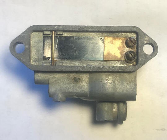
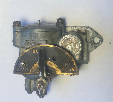
Carburetor ; Both the A1 and B1 use the same carburetor, on these the reed valve is mounted inside the rear of the carburetor. It is made of a flat sheet steel spring with dimensions of .005" thick, .562" wide and 2.196" long, with two .138" dia. .312" apart, with these holes centered .120' form one end. The stop is a long screw from the top of the recess, but positioned in a location to not allow the reed to move more than about 1/8". Seen in the LH photo, on top of the screwed down end of this reed is a backer made of .031" brass and 3/4' long.
The fuel line from the carburetor is a 3/16' copper tube. This model uses a fuel shut off valve threaded into the bottom starboard side of the carb. The air intake is about a 9/16" hole on the bottom Port side.
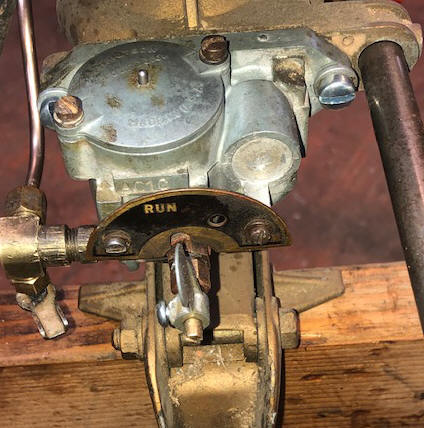
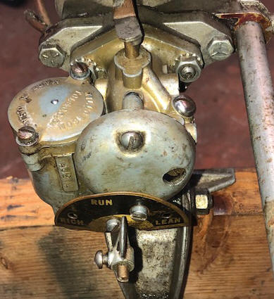
The carb on these motors does not have a idle adjustment screw, but only a main fuel adjustment, activated by the lever in the front. This lever can be adjusted on the stem of the needle by a setscrew on the starboard side. The usual initial setting would be about 1/2 to 3/4 of a turn out. - NOTE - There us no carb throttle timing advance arm, therefore the higher the speed / more fuel, appears to be simply increased as the vacuum inside the motor is increased.
One thing that does get lost on these motors is the carburetor main fuel adjustment lever. One of my motors was missing it. Well, I still have access to one of my son's CNC milling machines, so by using the original as a pattern, I Cadded out a new one in 2 dimensions. This was made of 1" X 1" square 12L14 steel. I made it a slightly different to facilitate manufacture, but overall it resembles very closely the original part. And it is made of steel instead of pot metal.
| Here you see the original lever | Here the new aftermarket one I made |
These motors are primed by depressing the center float pin where it sticks up out of the top of carburetor float chamber (as seen in the RH photo below), this is sometimes referred to as a "Tickler".
|
Here you see the reed valve, built into the rear of the carb |
Here the front view of the carb, with the fuel line inlet on the bottom left |
 |
 |
These particular 15 series motors were again built in late 1945 or early 1946 of left over parts. This one had sat for MANY years. Miraculously, about all the parts were there other than the tiller handle and fuel line, and the motor was not frozen up, along with the skeg was still intact on one. Running a compression test without oiling the cylinder was 60#. WOW, maybe I hit pay dirt on this one.
One of the carburetors was missing some parts, like the complete idle needle and packing nuts along with the drain plug. Here I cannibalized the idle needle unit off an 2 1/2hp 1947 Elgin junker carb. It was slightly different, but the right length and will work. The drain plug is totally different in that it is 1/4" X 32 TPI, being a nonstandard thread, so I had to make on on the metal lathe. This same motor had a short fuel line, possibly off another motor or the fuel tank had been changed, which I replaced by a new longer section of 3/16" copper tubing.
| Here the Tillotson #AC-1C carburetor on the models 15A & 15Bs - NOTE - no carb throttle timing advance arm | Here the Tillotson #AJ-21A carburetor on a model AA! - NOTE- the separate intake manifold |
 |
 |
These motors are both primed by depressing the center float pin (tickler) where it sticks
up out of the top of
carburetor float chamber, which overrides the float valve and allows some gas
into the intake manifold/reed valve area to prime it.
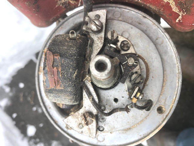
On the AA1, I first removed the flywheel, removed the points, flushed the timing plate off with
lacquer thinner, filed the points removing any oxidation, reassembled everything
on the timing plate. The coil looked OK, but how to tell if the
condenser would function. I reassembled the flywheel, held onto the spark
plug wire and cranked it over. NO SPARK. So back to the drawing board.
After doing some web surfing I found Doug Penn appears to have bought out the remains of the manufacturer some years after they finally shut the door (but he subsequently has resold them). Also on his website, he shows on a video how to test both the coil and condenser of older OMC outboards. CLICK HERE for a coil testing video, and HERE for a condenser testing video. I figured that these magneto parts were basically the same as the OMC parts he was lecturing on, so checked out the coil using his method which it then proved fine. Not possessing the equipment to test the condenser, I just inspected the wiring, found that the condenser wire was standing high enough to rub the flywheel magnets. Re-routing this wire solved that problem. It now shocked me if I held onto the plug wire when cranking the motor over, so spark appeared OK. But it would not fire off.
(1) Most condensers are replaced simply because the cost is low as compared to labor for trouble shooting the electronics later, if it doesn't run.
(2) His method of telling if a condenser is bad, is look at the points, if they are pitted badly, it is because of a failing condenser. However if the points look evenly worn, just clean them with lacquer thinner, drag non-waxed paper like a brown paper bag thru the contacts a few times, adjust them and 99.9% of the time it will run great.
| AA1 Magneto plate | Here 15B1 Magneto plate, note the condenser is missing, BUT it is in front under the timing plate |
|
|
 |
OK, do what I should have done first off, check the compression. Only got
40#, after 3 pulls, which I doubt was enough to make this little single cylinder
motor run. I pulled the head, tipped the motor up so the cylinder was
upright, and with the piston up above the port holes, poured in 1/2" of Seafoam. After a day it had all soaked down past the rings. A clean up of any oil
in the cylinder then a strip of 100 grit emery cloth rubbed rotationally inside the
cylinder walls with the piston bottomed out did a cheap hone job. The
compression was then raised to 70# after 2 pulls, which I thought was quite
respectable.
Inspecting the fuel tank revealed some rust inside. I then poured about a 1/2 a pint of gasoline along 2 hand fulls of abrasive triangle tumbling stones inside, tightened the cap and began shaking when ever I got near the tank for 2 or 3 days. This got out most of any loose rust that I figured would ultimately loosen up.
Almost ready, but this time I used a spark tester set at just over 3/16", when cranked over it light up like a Christmas tree. Choking it by tickling the carburetor along with using a bit of starting fluid sprayed in the carburetor throat, it popped on 3rd pull, started on 4th pull. Now to adjust the carburetor settings.
| AA-1A / WC-1 illustrated electronics | Here the nomenclature |
|
|
|
Carburetor ; The model AA1 was fitted with a Tillotson carburetor #AJ-21A, here is a difference in this later version than the previous 15 series ones in that there is now on the 1.7hp, a separate intake manifold and a new style reed valve plate. Also this newer carburetor now has a idle adjustment screw, and the carb was redesigned to have the air intake in the front, along with a domed shape front cover.
| Illustrated view of the carburetor #AJ-21A |
|
|
One point of interest, if you are used to newer twist grip throttles found on most other motors, you assume that the throttle/timing plate moves right handed. However with these motors that do not use a twist throttle, the timing plate increases the speed as it is moved to the LEFT. To start these motors, you need to position the timing plate knob slightly beyond center and to the left otherwise you may be cranking for a while.
This carburetor was improved by adding a idle jet on the front port side. And you will see most now with a AJ-21A round domed shape carb cover, that has a 5/16" hole where the idle needle is accessed.
Muffler ; The metal tube at the rear is defined in the parts list as "Exhaust Tube". I have seen some (especially the Pre War) that this tubing was brass. Later it seems that steel was the norm. Many of these mufflers have not survived well, (especially the brass ones) as they were thin and being the muffler right out of the cylinder became hot and easily distorted. Replacement steel tubing 1" OD by .032" wall thickness is a commonly stocked item at major distributors. However, you usually have to buy 6 feet of it (at a price of $48.75 plus shipping) in order to get the 18 7/8" or19 9/16" (depending on the model) needed to replace a damaged tube. But looking farther, I did find online on eBay, 24" sections of .049" thick for $7.39 with shipping at $15.65. I ordered 3 sections and got all of them for just over $15 each. This tubing being slightly thicker would be of no consequences and would be considerably stronger.
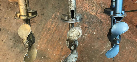
Of the 4 motors that I have, 3 three have a different exhaust outlet, from this, I can see an evolution, however there may be more). The 1945 has (3) .218 diameter holes drilled 1" from the powerhead and 1" apart. Where the exhaust tube sets in the gearbox/anti-cavitation plate it has no restriction, being exhausted directly above the prop. The 1956 has (4) .134" diameter upper holes, along with a .357" wide X 1.134" slot that is radiused on each end at the bottom directly above the anti-cavitation plate, however this previous exit hole out the bottom is blocked off. The 1979 has (4) .054" diameter upper holes, and as the previous version exits out the bottom of the anti-cavitation plate, HOWEVER, this plate now has added a small cast in clamshell scoop pointing rearward.
I can see a transition
here, where the prop in the earlier models would be pushing the exhaust back
up the exhaust tube/muffler. For the AA1, they blocked that bottom of
the exhaust casting off, and moved the exhaust outlet up to the slotted
hole. Then on the 500, 700 and 800 a clamshell was added as seen in the
RH side of the photo below.
Also in the earlier 2
versions, the water return tube goes all the way to the bottom and out
through the anti-cavitation plate. The word from somewhere was
that since this water pump was a centrifugal aluminum pump as compared to a
later rubber vaned pump, that with the outlet tube going clear down and out
the anti-cavitation plate, this outlet lower part would fill with water and
sort of act as a siphon. ??? On the 500 and 700 series the
outlet tube is cut short and fitted INTO the side of the upper part of the
muffler. I see this as an advantage by, in addition to quieting
the motor, it also cools the muffler ensuring that the paint is not burned
off. This also secures the tube from rotating.
One thing that you may notice in the photo below, is the earlier motor on the left (the15B1) has a shorter driveshaft/muffler unit by about 3/4", than all of it's later AA1 or 700 cousins.
| Exhaust outlets have changed over the years |
 |
Water
Pump ; Three
1/4" oval head
screws hold the lower unit and driveshaft in place. By removing
them allows the driveshaft and gearbox to be slid down and off the upper
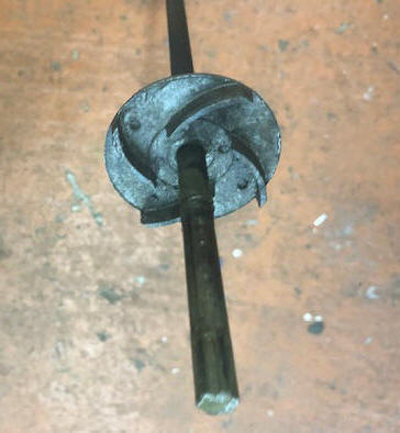
part of the motor. This exposes the centrifugal water pump impeller (which is pinned
to the driveshaft). The top of the impeller is solid, with the vanes
on the underside. This pump is a 4 vane aluminum .420" thick by 2.350" diameter. This water pump is mounted directly above the anti-cavitation
plate.
Here, close tolerances apparently are not considered, since this small motor's cooling needs are minimal.
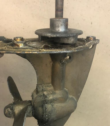
In the photos of the gearbox section below, you can see the water intakes (one on each side) about 1" below the anti-cavitation plate and in the raised boss where the driveshaft extends into the actual gearbox.
On these motors, both of the water tubes, outlet from the water pump AND the water outlet from the block are simply 5/16" copper tubing and can easily get bent. No big deal, just simply bend them back.
Being such a small motor, the cooling water does not circulate through the head. The water goes in a bit on one side, but not through the head like most larger motors. However the outside of the head has cooling fins as if it was a air cooled motor. The head is held in place by (3) 1/4" studs with nuts. The top stud also is the rear anchor for the fuel tank.
Shown in the photo below is a complete gearbox with the water pump impeller pinned to the 3/8" driveshaft.
| Water pump impeller as viewed from the bottom/gearbox side |
Water pump impeller in position on top of the gearbox |
 |
 |
Gearbox ;
To remove the rear cover plate which also encompasses the prop shaft, remove
the (2) 1/4" X 5/8" oval, or flat head screws at the rear of the cover. Inside the gearbox are a set of simple
brass bevel gears. The drive gear is splined to match the driveshaft.
There is one steel thrust bushing on top of the drive gear.
The grease fitting plugs are .402" dia. X 28 NF TPI threads.
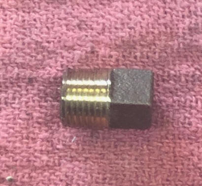
I have not found any 1/8" pipe plugs with no head, with a screwdriver slot,
so I purchased a regular square headed brass plug and modified it. The
head needs to be removed so you have minimal obstruction at the rear of the
gearbox in front of the prop. Here I screwed the "as was" plug
in enough to be able to tell how much of the head needed to be cut off.
Just hacksawed most of the square head off, bandsanded it down and
made it slightly radiused on the top. Then I cut a screwdriver
slot using my Dremel tool and a slitting saw abrasive stone.
FYI, -- pipe fitting threads are slightly tapered so the deeper you
thread them in/on, the tighter they get.
As a side note
here, you can make a grease fitting adapter (using 1/8" pipe, using a grease
fitting, pipe coupler and a short section of pipe), and use it to facilitate
filling the gearbox with boat trailer grease.
| Here a regular square head 1/8" pipe brass plug | Here the plug after modifications |
 |
 |
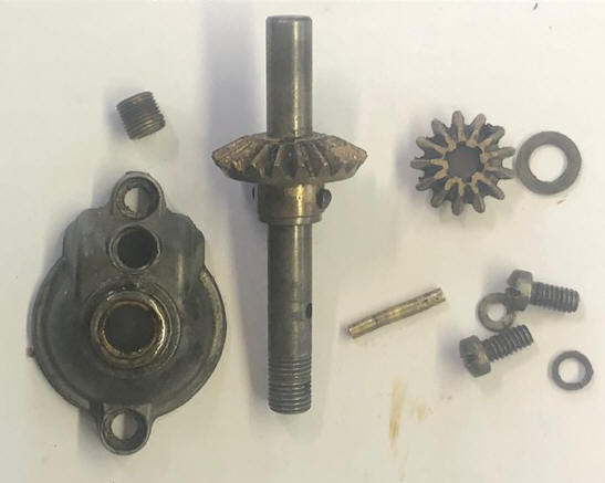
As seen in the photo below, the 6 splines are visible on the inside of the small drive gear.
| Here are gears removed from the box |
 |
| Illustrated view of lower unit & mounting bracket assembly |
|
|
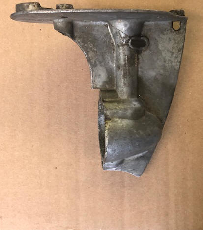
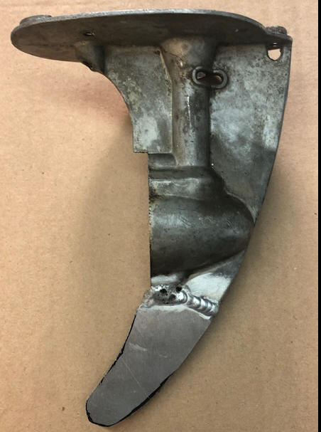
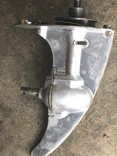
Broken Skeg ; Since this motor had a broken skeg, by using 1/8" aluminum sheet, making it oversize then Heliarc weld it onto this gearbox. Then by copying the shape off my other original motors, contoured the new welded material to match. Any pinholes in the weld was filled with Bondo and sanded down.
You will note (from the LH photo below) that the front contour arc continues all the way to the lower end, and is a total of 7 1/2" from the top of the gearbox to this lower tip. The rear of this skeg is again made in an arc, with the lower diameter being 1/2" and extending 1/2" rearward from the rear of the gearbox shaft rear housing.
As seen in the photos below, the before/after of this repair. The RH photo is a bit oversize, so needs to have the final matching shape and smoothing out of the weld. This one also had a crack in the housing's water intake cavity from the upper corner of the RH intake angling up to the anti-cavitation plate (as seen in the center photo below). This was probably not as significant as the skeg, so it was Veed out and filled with aluminum solder.
| Gearbox housing with broken skeg | Gearbox housing with welded skeg |
 |
 |
Lower Unit Seals ; In observing the above exploded views, #9, #13 oil are seals. However while having this one apart for welding the skeg, these 2 parts appear to simply be bronze bushings, at least on my AA1. And this gearbox uses grease that that is thick enough that it appears does not leak out a lot.
One thing that seems to be usually overlooked in these repairs is the seals both above the impeller in the housing and below it in the gearbox as an oil seal on the top of the gearcase (#9 and #13 in the illustration below). The EARLY top one appears to be some kind of Nylon 3/4" OD X 3/8" ID and 3/16" thick. It usually stays on the driveshaft when disassembled, retained by the splined coupler on the top of the shaft. The bottom grease seal is _____________________
Propeller ; In all these models, they use the same prop which is a 2 blade LH, 6" dia. X 5" pitch & pitch 6″ X 5″, which are made of aluminum. The shear pin is made of brass and is 5/32″ dia. X 1″ long. The prop nut retainer cotter pin - 3/32" dia. X 1 1/4" long. The prop nut is a brass acorn type and 7/16" NF.
Gearbox Reassembly ; In reassembling this gear box, here are a few tips. But first you need to clean it, and make your own gaskets. You also need to remove the water tube exhaust from the powerhead.
(1) Slide the driveshaft with attached water pump impeller into the gearcase shaft hole. (2) install the drive gear inside the gearbox, on the splined lower end of the driveshaft. (3) Pump some grease into the housing to help pre-lube this gearbox. (4) Slide the brass .020" thrust washer onto the front prop-shaft. (5) Slide the prop shaft and driven gear into place and mesh it with the drive gear. (6) Install the gasket and slide the rear gear case cover in place and tighten the (2) 1/4" fillister head screws and lock washers.
(7) At this point, DO NOT now pick this unit up by the driveshaft which ALLOWS the driveshaft to slide UP, disengaging the drive gear from the driveshaft spline. (8) Install the exhaust tube in the power-head socket. (9) Slide the now complete lower unit it into the driveshaft tube, engaging the square upper end of the driveshaft with the lower end of the crankshaft (this may take rotating the flywheel). (10) Align the exhaust tube into it's mating recess in the lower flange. (11) tighten the (3) 1/4" oval head screws attaching the gearbox to the lower flange of the driveshaft tube unit. (12) reinstall the water exhaust tube. (13) Grease the gearcase.
In the original (downloaded in pdf) owners/service manual says to use "Non-Channeling waterproof grease". Here is the definition. Non-channeling indicates that IT WILL stick to the gears. What I use is LubriMatic MARINE CORROSION CONTROL trailer wheel bearing grease which has a dropping point ?? of 550 degrees Fahrenheit. This grease is filled through the single plug screw hole at the rear, and above the prop-shaft,. -NOTE- some gear case cap covers have one, while others have 2 plugs, usually these are the earlier motors.
This grease, in order to have a full gearbox, has to be forced in with a pump. Initially I thought that i could simply use a short 3/8" bolt with the center threaded to 1/4" SAE, which a small thread Zerk fitting is screwed into, and the simply use my wheel bearing grease gun. WRONG, the plug screw threads are .402" OD X 28 TPI, which is not any standard bolt thread, so time to fire up my lathe and make my own Zerk fitting adapter.
NOTE - as mentioned in the #4
above, this washer does not show in the parts drawing. Therefore it
may be something that is installed upon assembly (and fitted) to ensure
there is no slack in the gears, so it may vary in thickness depending on the
individual gearcase.
As seen in the RH photo below the
water pump impeller just rests on top of the upper part of the gearbox's
anti-cavitation plate.
It is held in place by final assembly with the upper square of the
driveshaft engaging the engine's crankshaft.
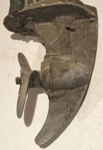
| An original crudded Gearbox housing | Gearbox repaired & reassembled |
 |
 |
Final
Product ; In the photo on the left below shows
this restoration motor right after I got it running but before any cosmetic work
being done other than replace the 1/2"
aluminum rod for a tiller handle.
Also it appear that for
this motor to be "as issued" it needed the cast aluminum side skirts.
Researching this, exact replacement decals are available for $34.50, now to find matching maroon paint, as the rest of the motor is silver. And I have a pair of side skirts on order to round out this deluxe AA motor.
| My AA-1 before, but right after it was running | Final after |
|
|
This may take a while as the house needs painting |
It is hard to get good real life original photos of these motors because of the abuse they have suffered over the years. And MANY DIY home paint jobs done during the motors previous life do not help those of us who try to restore them. It appears that some of the tank colors may have been different depending on the models and years. ??
The decals read “Neptune”, although the sales literature called them “Mighty Mite” from 1957-59. Starting in 1960 and continuing thru 1969 the most common Mighty Mites, were made at Cordele Georgia.
For a pdf exploded view of the WC1 and AA1A motors CLICK HERE
From what information I can piece together the following is close (and I may have some
possible omissions) to the
year/model for this style of the single cylinder motors which later became known
as the "Mighty Mite". There were others made prior to this date, but they
were of a different style, or were twin cylinder motors.
You may notice some collation between the model numbers and the year of manufacture up until 1942 during WWII, then a carry over of prior parts, assembled in 1945/1946 with production resuming and the model numbers again being added in 1947. Then there appears to be a carry over of model numbers into years some later years. From 1948 on was a different story.
I have not been able to track down any serial number references however.
The below in formation was copied from the Copied from Antique Outboard Motor club forum, with some addition on my part, but still some questions arise.
The models listed below are for only these small HP motors made by Muncie Gear Works, not listing the other larger models, as these are only what we are covering here.
One thing
that I have found is listed below, In those early years Muncie Gear Works
sold motors to different outlets, and in doing so they separated the model
numbers, where the (2nd letter) for the Neptune model is an A (as 17A1) or
(17B1) for the same Muncie model. Then later, they also did the
same, but with the first number as (1A38) or (2B38).
Also this list will be different than other published ones as it seems that
it was for all Muncies and not just the small single cylinder Mighty Mite series that we are
dealing with here. If the model included a 2, (as OB12) it would
have been a twin cylinder 2 1/2 hp motor.
The last number represents the HP, (1) being1hp, but under 2, and usually1.2 / 1.5 / 1.7hp. (2) would be 2HP, here usually 2 1/2hp. (3) would be in the 3HP range, etc. Now since I am not an Mighty Mite expert, this list may not be complete. If you find one outside of this please contact me.
1936-37 OB11, OB11A
1938 1B38,
1939 1A39,
1940 10A1,
1941 10A1, 11A1
1945-46 11A1,
15A1, 15B1
1947 17A1, 17B1
1948-55 A1, AA1, B1
1956 AA1
1957-60 AA1-A
1961-69 WC-1
1970 500
1978 700
1979
700 CDI,
Mighty Mite II
1980-86 800, 800B, 800 CDII Mighty Mite III
It seems that on a motor model that the 2nd letter being another letter (as
AA1) possibly designates a deluxe version, in this case probably was supplied
with side cowlings. I know of at least two motors that has an X as a last model
number. But have no idea of what that means.
The original recommended fuel mix at the time these motors were made was 16-1 as the
main bearings are just bronze instead of the newer roller type. But the more
critical connecting rod bearing is simply the aluminum rod and cap (no
bronze insert).
Now comes the $64 question, will using new full synthetic oil function at 24-1 or possibly 32-1,
work on these motors ?? One part of me says NO, as the crankshaft
seals are not that efficient, needing a thicker fuel mix. However the other part of me says YES as
the full synthetic outboard oil has considerably better lubrication
qualities. ??? I guess it would be up to you.
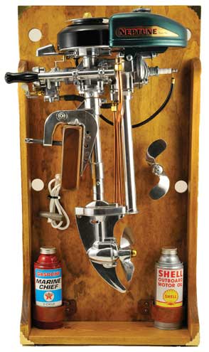
In the photo below this particular motor has had the shaft shortened considerable, apparently to fit in a more compact display.
| Here is a fully restored 1947 AA1 mounted in a display |
 |
Recommendations ;
At the end of your
day of running these motors, it may be a good idea to turn off the gas and run the
carburetor bowl empty prior to pulling the motor out of the water. Also make sure the screws are tight
on the handle and all the others around the engine. If not, they will vibrate loose, ending up in the
water. Pack the gearbox with marine wheel bearing grease. It
may also be a good idea to put rubber or nylon washers on the gas tank mounts to ease
vibrations to the tank. This motor tends to crack the gas tanks.
Observances ; It was not clear to me as to the increase in HP why the displacement was the same on the prewar 1.5 hp as compared to the later 1.7 hp motors. Finally after a lot of digging, I think that I figured it out. The pre-war motors used a totally different carburetor design. The early carbs used a simple vacuum for sucking in more fuel as the timing plate was advanced. The later carbs used a carb butterfly throttle arm control in conjunction with the timing plate advance lever, which timed the higher fuel supply to match the timing. This gave them a more controlled/synchronized fuel to timing ratio where the high speed gained 1,000 RPM.
I have tried to visualize the transgression of these models through the years, BUT it is becoming pretty clear that the models listed (at least in the 1945/46 date), there may have many that used cleanup parts from before the Pre War production. The one thing I see that is confusing is the fuel tank configuration, some are the square sterned while others in that year range are tear dropped. OR over the years there is a possibility that some owner may have made a switch.?? I have later learned that it appears that the last years of the teardrop gas tank was in 1956 with the model AA-1.
I guess what I am saying, HERE there may not be a cut and dried yes/no line of what the original motor may have looked like when it left the factory for those of you who are trying to restore one. The same may also be true as to original colors. ALSO, if this could happen, so could the brass ID plate under the flywheel nut may have been also changed, which would totally screw up the average new "collector". If I am wrong and some one more knowledgeable than I, PLEASE HELP ME OUT.
I have a feeling that many of these motors (the deluxe versions especially) were supplied with the side covers, after a while the owners discarded the covers, as it appears the were hard to keep tightened. And the motors ran just as well without them.
It seems that the collector interest for these engines runs mainly into the older pre 700 series where the plastic cover and lawn mower starter seem to cheapen the interest.
The 500 ; The 500 model was introduced in 1970 and was basically the WC-1 motor with a yet another totally new carburetor (using a butterfly choke), water exhausting into the muffler below the power head, side skirts and a different paint job, examples seen could be the more common gold, or less common turquoise color.
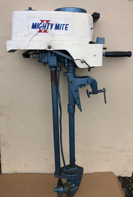
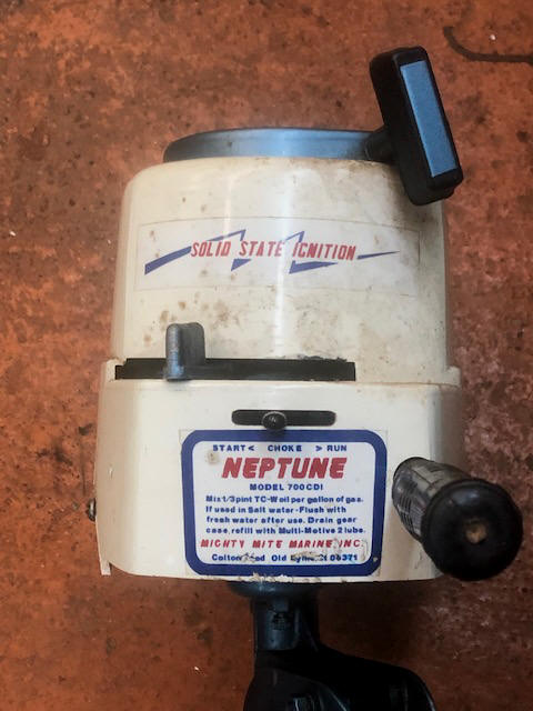
The 700 CDI ; I have since acquired a Mighty Mite II 700 CDI with a s/n of 7326 from one of our fishing club's annual yard sales, brought in by a widow of a club member. This was apparently made after 1979 (as the carb has a stamping of 7-79) and is listed as a 2 hp. The fuel tank is some sort of plastic, with a white fragile plastic outer cowling covering the fuel tank and sides of the motor. On top is a recoil starter very similar to those used on a lawn mower.
For this model the recommended fuel mix is Oil 1/3 pt. (21-1) SAE-30 per Gal. 1 gallon = 128 oz, 1 pint = 16 oz, 1/3 = pint 5.33 oz.
| Here a Mighty Mite II, 700 CDI | Here the 700 CDI shows the front panel & the Old Lyme, CT address |
 |
 |
|
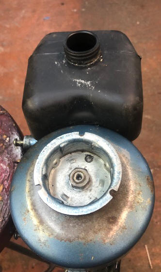
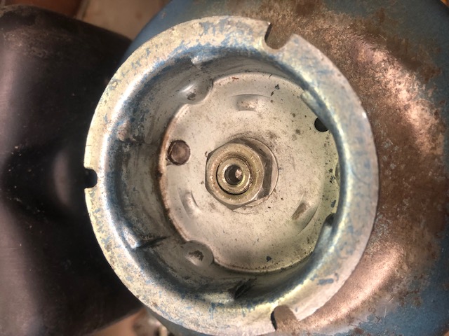
Here you see the plastic fuel tank & the extended new style starter receptacle |
Here you see a close up view of the starter receptacle ratchet protrusions |
 |
 |
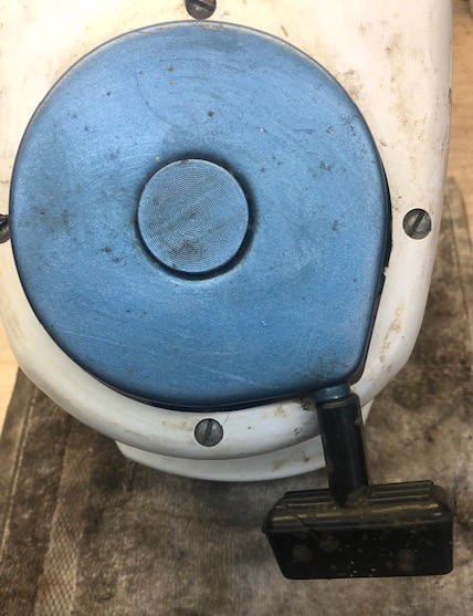
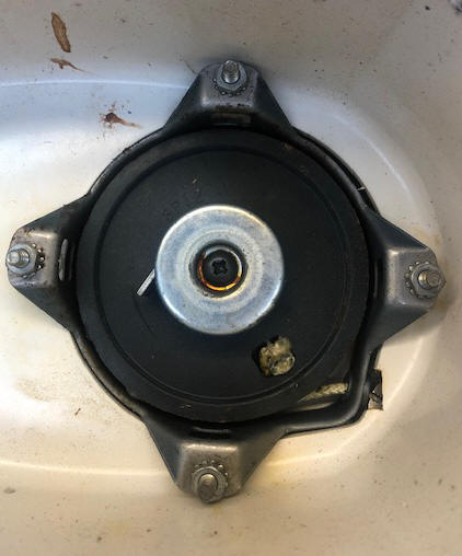
| Here the top of the lawn mower type starter unit | Here you see the underside of the starter with the rope partly pulled exposing the engagement lug |
 |
 |
Here, as soon as I got it, after cleaning the dust off, I ran a compression test, 75# good enough for me, maybe just fill the fuel tank and see if it starts.
This carburetor with only the name WARBRO USA on the bottom of the bowel, more in line with modern day push lawn mowers (same as used on the model 500) instead of using a float bowl tickler if it's predecessors, has a standard butterfly type choke and a removable stamped aluminum float bowl, with a adjustable main jet in the bottom of the bowl.
Here there was no known information. It looked in pretty good condition other than the cracked new plastic motor cover. However trying to get it to pop in a dry run test situation proved totally fruitless. Working solo, it is hard to test the spark, so I just grabbed the plug, grounded my fingers to the block and pulled the cord. I got no shock.
In removing the flywheel, I encountered the nut was on VERY tight, WHY for this small motor? Upon closer inspection it was missing the flywheel key. Apparently someone had lost the key and tried to tighten the flywheel enough in the best location was their intent, but it apparently was not properly aligned to the crankshaft slot creating an out of time situation. I had preciously made up some of this blank key stock in the proper dimensions for my earlier other Mighty Mite repairs, with a lot of it extra, so cut off 3/4", deburred it and reinstalled the flywheel. Another pull of the cord and I got a mild shock. Bingo. So with a squirt of starting fluid and another pull on the cord, it responded.
But in the reassembly, and having to tip the motor upside down to locate and fasten the throttle lever and cowling mounting screws, there was LOTS of oil leaking out of somewhere. After thinking about the situation, then tearing it apart again the next day, I found this oil apparently was coming out of the carburetor. This oil was not black carbony, but more like fresh out of the can. My only guess is that someone in trying to "winterize" had squirted lots of oil in the spark plug hole. And over time with it laying in the just right position, this oil moved through the cylinder and intake opening into the carb. OK, while it was off, I might as well soak the carb in my 40 year old can of carb cleaner.
Then when reassembling, the Vinyl fuel line was so hard, that when taking it off the carb was a chore, obviously I needed to also replace that. The original one was 5/16" ID X 1/2" OD, but was so heavy that no clamps were used to hold it in place. The replacement one that I got was thinner 5/16" X 7/16" which should be no issue as there is no pressure on this, along with now I can use small size Zip ties as clamps on the fittings.
Now fill the fuel tank and see if I can get it to start. BIG problem,
the fuel shut off valve on the outlet of the tank was LEAKING. By
pulling the valve stem nut loose, I could tell it had to be leaking around
the stem, but no way to get to any packing. So by grinding off the
flared over stem on the bottom of the valve handle, I got it apart.
Now by careful probing, removed a small Neoprene O-Ring. Now just to
try to find one at the local ACE hardware store that size, and then soft
solder the handle back on.
The 800 ; The 800 series abandoned the two column midsection in favor of a new unitized column.
| Here a Mighty Mite III, 800 CDI |
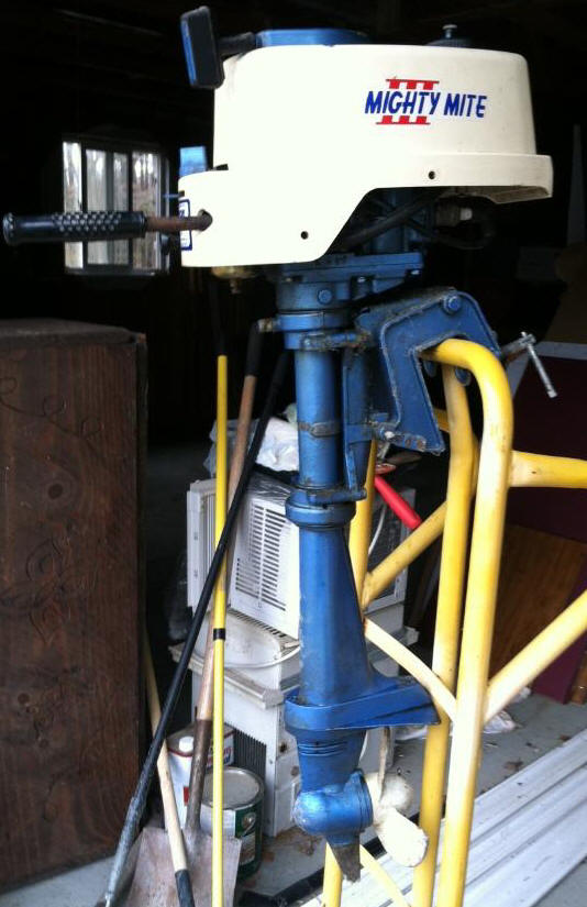 |
More Observances ; This 700 series was the start of a new outward look, however most of the rest of the motor was the same. First thing is that is is fitted with a white plastic shroud, that seems to be pretty susceptible to cracking. The other obvious visible item is it sports a lawnmower type recoil starter. And the color of the metal parts is metallic blue. It has a completely different carburetor, where the choke is now a butterfly version as compared to being a carb tickler. Another observance over it's predecessors, the water exhaust tube from the powerhead was shortened considerably and inserted into the muffler (the exhaust tube). This supposedly solved a noise issue along with cooling the muffler, therefore not burning the paint.
http://www.nymarine.ca/colours.html
http://www.discount-marine-parts.com
Carburetor kits #3345 available from
The Carburetor Shop LLC
204 East 15th Street
Eldon, Missouri 65026
Decals available from @ $34.50 a set
American Outboard Motors & Salvage
12611 Ocean Gateway
Cordova MD 21625
410-862-1740
http://www.americanoutboard.com/decals/neptune/master_neptune.htm
"Hard core parts for some of these outboards are getting more difficult to find
as time goes on. Many older outboards used common Ignition and Carburetor
venders for that period. Discount Marine Parts has Ignition and Carburetor
repair kits for most all of these older outboards. If we don't have what your
looking for, we have many sources to locate your part. Obviously some parts are
just not available. We can sometimes find it used and often we have the part
made if there is enough demand. Discount Marine Parts has a large inventory of
parts for most brands of American made Outboards, Inboards and Sterndrives. We
also have most parts and service manuals available."
Copyright © 2011 - 2023 LeeRoy Wisner All Rights Reserved
Back to the Main Ramblings
Page
Originated 03-02-2011, Last
updated 05-27-2023
Contact the author