 |
Maintaining Johnson/Evinrude 9.9 & 15 hp Outboards 1974 – 1992 (Converting to Electric Start) |
|
 |
Maintaining Johnson/Evinrude 9.9 & 15 hp Outboards 1974 – 1992 (Converting to Electric Start) |
|
This article is not meant to be the bible
for these conversions, but to give you some guidelines,
Do not send me a e-mail plea for
part numbers & where to buy these parts, as they are LONG OBSOLETE.
Your
best bet would be to try to find a JUNKER possibly on Craig's list & cannibalize it.
Here, the Red-Neck electric starter can be simply a battery operated drill motor, a socket extension, cut off to fit the drill chuck and a 7/8" socket. HOWEVER, when it starts, you need to be QUICK to raise the drill, disengaging it with the nut, as many times, the motor then will be running faster than the drill and the nut will come loose, AND GO FLYING. This might be at home on muffs, but if on the boat and on the water, maybe not so good, UNLESS you are carrying a spare nut in your tool box.
Converting
Over to Electric Start, BUT NO Charging System :
This
would be the easiest
to do with just
a electric starter style but without the charge capability. This would involve
replacing the
right flywheel (with starter ring gear) to match your ignition system (or at
least be compatible),
bypass cover that acts as the starter motor mounting bracket, wiring from the
battery to the push button switch then on to the starter.
It
just will NOT recharge the battery. A fully charged battery may last
a week
of normal electric starts however.
The electric
start does come in handy to start the motor for us older geezers who may have
physical problems or if in a somewhat emergency
situation, or if you are using the motor from a front console or steering
station.
Try to find a flywheel
off a model near to your year, however I have just received correspondence where
a guy did just that with a 81 who used a 90 flywheel so it worked for him.
If you are newer than 1977 you can not go
backwards on flywheels into the 74-76 series (unless those are the years you
have) as those used magneto ignition. Sorry I can not help with flywheel
part numbers as I do not have access to that data, being a shade tree mechanic.
Doing it this way the battery will not be charged by the
motor, however these motor's alternator is so weak that UNLESS you run it at
high RPM it will not maintain the battery anyway. Also this way you do not need
any of the other electronics under the flywheel or wiring to the rectifier or
even the neutral safety switch. These electric start motors do not use a
starter solenoid but a Heavy Duty button inline AND direct to the starter.
Do not get a used starter unless it is cheap as new ones go for just a bit over
$100.
Converting Over to a Full Electric Start /Charge System : This full blown electric system involves all of the above plus a lot more. It can be done, but may not be cost effective if you price new parts (which may not now be available) depending on the year of your motor. This charging system only has a 5 amp output at full 5000 RPM, so at 600-700 RPM idle speed, you will not be charging enough to even maintain a battery that is also being used as a starting /sonar battery beyond a few days (been there - done that).
The simplest would be to buy a complete used set of parts, or another motor that has a blown powerhead or lower unit. As you can see from the information on the regular article that the ignition and therefore also the charge units are vastly different. So you would have to acquire your new /used parts off motors that use the same electronics. Starters and the by-pass cover are the same from 1974 up to 1992. The under the flywheel parts differ and are matched into families of the motors "improvements" over the years.
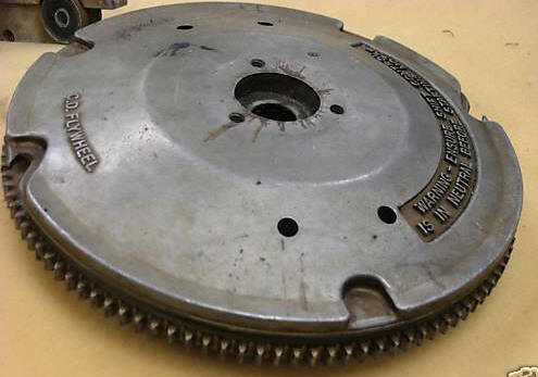
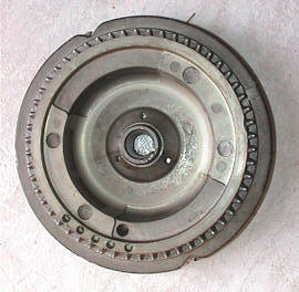
When it comes to flywheels, new ones are expensive if even available now-days and trying to find the right used one may take some time. There are differences in the electric start flywheel over the rope start type. The rope start version has only the larger cast in aluminum toothed lower gear, while the electric start in addition to the manual start cast in gear, has a steel ring gear for the electric starter to engage into which is larger diameter which is placed higher on the flywheel.
I will list these parts by transgression of the 4 OMC electronic ignition systems. The type numbers listed below are MY NUMBERS only and are used for clarification for the different systems I have identified here. At the time they were in production, the factory had no idea what improvements were to come along during this series of motor lifespan, so in looking back, we can now categorize them into types. Again these are NOT factory designation numbers.
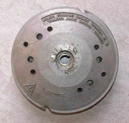
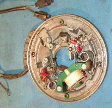
My Type I would be the 1974-1976 that has a straight magneto setup under the flywheel with points and condensers to external coils for each cylinder, then on to the spark plugs. This flywheel will have cast into it words like "points need to be set at .020" and will have point setting marks for both top and bottom cylinders. However without inspection holes in the flywheel, it is impossible to locate the crankshaft rotation to set these points at the marks unless they are using a special plate.
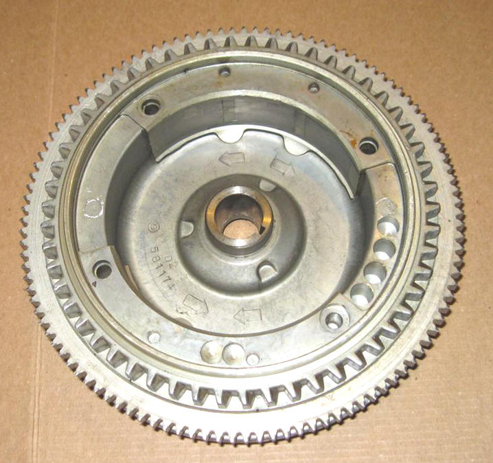
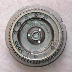
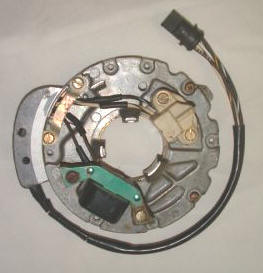
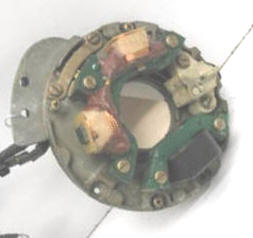
My Type II would be the electronic ignition of the 1977-1984 which have electronic Capacitor Discharge Ignition, sometimes called a CD Ignition, or as OMC called it then, Mag Flash ignition. This has a charge coil under the flywheel that sends a small voltage to the power pack, which ups the voltage to 300 volts, which is then sent to individual external coils and on to the spark plugs.
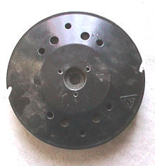
My Type III is from 1985 thru 1988 a supposed to be a slightly improved version of the system and was called CDII. All the above flywheels are cast aluminum with metal driveshaft hubs with the magnets cast into them. I believe the flywheels are interchangeable between the Type II and III types. These flywheels are painted black.
My Type IV is from 1989 thru 1993 another system called the UFI (Under the Flywheel Ignition) was used. These flywheels are also painted black.
The 1993 to 2005 2 stoke uses a totally different system as to size and shape so no parts will interchange off these types.
|
Type I rope start 1974 - 1976 |
Type I electric
start 1974 - 1976 |
Type II rope
start 1977 - 1984 |
Type II electric start 1977 - 1984 |
|
|
|
 |
 |
|
|
 |
 |
|
 |
|
 |
 |
One thing to be aware of if you tend to buy used parts off eBay or even elsewhere, is that MANY sellers do not know what interchanges with what. Just because the motors were made from 1974 to 1992 does not mean that all the parts interchanges as some so called shade tree mechanics may think. And most of the e-Bay sellers will try to sell the flywheel separate from the timing plate /driving coils. This is bad if they don't know the year the parts were off of where you are trying to find something in a compatible year that hopefully fits your motor. And trying to decide what flywheel fits what is rather hard as there appear to be superseded flywheel part numbers not listed on the yearly printed parts lists. Also if you are trying to upgrade your motor to a electric start / charge system, the flywheel needs to be compatible with the timing plate / driver coils.
|
Type III rope start 1985 - 1988 |
Type III electric start
1985 - 1988 |
Type IV rope
start 1989 - 1992 |
Type IV electric start
1989 - 1992 |
|
|
|
 |
|
|
|
|
 |
|
|
|
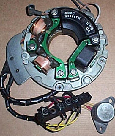
need to find a motor to photograph. but suspect the same as Type 2 electric start or very similar | The rope start version is basically the same as the photo on the right except that it does not have the 2 copper wound charging coils nor the rectifier or the wires leading to it |
 |
The part numbers listed below should be cast into the actual flywheels. Some later run superseded flywheels may interchange with the numbers shown below that were taken off existing known year parts manuals. Also some flywheels may also interchange with the different charging systems like possibly the type II and III systems??
| This table shows actual OMC flywheel part numbers, however there could be others which may have been superseded & not listed in published parts lists | ||
| Year | Rope start | Electric start |
| 1974/75 | #581216 | #581175 |
| 1976 | #581423 | #581175 |
| 1978/79 | #581676 | #581693 |
| 1982 | #582141 | #582144 |
| 1987 | #583007 | #583078 |
| 1990/91 | #583913 | #583915 |
| more to come | ||
You need to get all the parts needed, as flywheel, timing plate assembly, starter, starter bypass cover bracket, start button, neutral safety switch, junction block, and rectifier. One thing to be aware of is that the timing plate cam on the motors from about mid 1980s on is simply a drop in / held in place by the timing plate base and the actual timing plate when they are bolted together. It is indexed by a couple of protrusions that go into recesses, which many times gets misplaced or the person does not know where it came from. SO if you purchase used parts and the person selling them is not familiar with this unit, you may well NOT get this cam.
You could put the complete "KIT" from any year motor onto any other motor within the 18 year series, no matter whether it originally was the earlier 74-76 points ignition or not. HOWEVER trying to upgrade the earlier 74-76 motors with later components will turn into a hassle as there is no provision for mounting the powerpack. And you would need to purchase the individual newer coils and powerpack in addition to the other conversion parts.
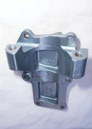
The old bypass cover that is located on the LH side of the motor is replaced by one that has provisions to mount the starter into using the 2 bolts that attach the starter. A word of advise, if you are considering this conversion, LOCATE the your new bypass cover/starter mount BEFORE you spend any money on a starter. Used electric starter mount covers (#319350) are scarce (and expensive, like possibly $150) IF YOU CAN FIND ONE. And new ones have not been not available for over 20 years. The reason is that you are not the first, second or even third person wanting to do this conversion and the bone yards have been picked pretty bare. Parts off junker motors with electric starters can sell for more than the motor in questionable running condition. If you were a good machinist/welder, you could fabricate one that would work, BUT YOU WOULD NEED ONE AS A SAMPLE TO WORK FROM.
Do not pay too much for a used starter as there are a couple of aftermarket companies who make and sell these starters for about $100 or less.
One thing if you do get a used starter, be careful if you have to remove the red power input wire. The nut that attaches the wire to the terminal usually gets rusty AND IF the stud that goes into the motor happens to turn inside while you are trying to remove the nut, you very well can twist off the inner wire. This is then almost impossible to reconnect that NOW SHORT wire internally.
| Bypass cover/starter motor mount #319350 | 74-92 electric starter |
 |
|
If you do find the right charging system, you will also need to be sure to get & install a rectifier in the charging system. There needs to be a connecting wire, (usually red) from the red wire on the terminal block to the incoming hot wire at the starter push button from the battery to make the system recharge the battery. There will be 3 yellow wires that will be yellow, yellow with gray stripe and yellow with blue stripes. These need to be connected to the terminals of the terminal block to the same color wires from under the stator / flywheel. You may find a rectifier that has an other wire that is usually blue. This blue wire usually goes to the kill button on some versions of electronics. These rectifiers are pretty universal on many sizes of OMC motors, if the boat is equipped with tachometer the yellow/grey wire usually goes to it.
When installing electric start/charging hardware on a manual start motor, the fuel pump inlet line will be in the way when attaching the electrical terminal block and rectifier to the powerhead's water-jacket. On the older electric start motors to avoid this problem, OMC simply rotated the fuel pump cover so the inlet points down, then re-rout the incoming fuel line under the motor mount. On the later motors they went to a newer style fuel pump that attaches to the other side of the motor with a bracket rather than directly to the motor.
The photo below is off a 1992 electric start but the connections are the same from the start of this series in 1974. This will be simplified as the fuel pump is different on the other side of the motor (connected by the black rubber tube) and it uses a different power pack under the flywheel, so does not obstruct wiring viewing in this photo. This may be slightly different in that on this one, as I ran the start wire over the top of the block to the starter, where the factory usually runs theirs under and around the front of the block.
As shown, the #1 red wire comes from the starter switch and attached to the terminal block. #2 wire attaches to #1 wire on the terminal block, runs down to the neutral safety switch. #3 comes from the neutral safety switch and goes to the starter. #4 smaller red wire comes from the rectifier to the terminal block, then forward to connect to the HOT wire from the battery on the starter switch. This is the charging wire to the battery.
| Wiring connection layout for electric start motor |
|
|
| voltage rectifier | terminal block |
|
|
|
The little permanent magnet starter motor used on these motors only draws 7 amps on open circuit, more when actually cranking the motor. These draw so low amperage that they can get away without using a solenoid if the wires are heavy enough. In wiring, the positive battery (+) cable and rectifier wire goes to one side of the push button starting switch, other side goes to one side of the neutral start safety switch. Another cable goes from the other side of the neutral switch to the starter. That provides start-in-neutral-only protection.
If you try to purchase an original OMC push button starter switch #395699, the cost was $46.85 in 2005, while you can go to a marine supply store, get a aftermarket Sierra 30 Amp switch #MP39160 for $15.99. Note - this can not be a standard 15 Amp push button automotive starter/horn switch because these motors up to 1993 do not use a starter solenoid, as the switch is directly in line from the starter and relatively close to the battery. A standard push button horn switch will burn up in usage because all the power energizing the starter, flows thru it at the time of starting.
If you are going to place the starter button, or a ignition/on-off switch in a remote position, like at the console or steering station, then you can use a lighter amperage button or a marine starter/on-off switch. Here I would use a small starter solenoid that will need to be placed near the starter using the heavier wire, run lighter wires from the solenoid to the forward switch. The original OMC solenoid for remote mounts under the carburetor (OMC #584128. $27.25).
However if you simply wanted a kill button in this forward location, then simply splice into the 2 wires going to the original kill button, run them forward to a simple momentary on button, grounding out the coils.
| Electrical diagram for manual starter motor | Electrical diagram for electric starter motor | |
 |
 |
|
| Click on the above thumbnails for larger picture | ||
The actual electric start flywheel is also slightly smaller than the rope start flywheel by about 1/4" overall diameter. This smaller size is to allow clearance for the starter shaft nut that extends upward at this area. The original electric start flywheel is made differently, which uses the starter ring gear as the lower edge of the emergency rope groove.
One thing you can do, is that you will have your old flywheel but you can only find a different ignition version than is needed, is to take it anyway if the price is right, then remove the ring gear. OMC does not sell just the ring gear as a separate item. I suspect it is not made by OMC but another supplier, since there are numbers and a trademark stamped on the underside of this gear. The numbers appear to be, j E:T.N 4 511208 ( M ). The M is inside a parallelogram. The inside diameter of this gear is 7.0" outside is 8.0", it has 110 teeth.
Have a machine shop, or if you posses a metal lathe, make a tapered shaft to fit the flywheel, or use an old crankshaft, mount your old flywheel on it, then turn your flywheel down to the EXACT size of the one that had the gear on it. Heat the gear with a propane torch. This will expand it just enough (just hot enough that you need a rag to hold onto it), Install it quickly by dropping the heated gear over the flywheel's newly machined surface. You might have to tap it into place before the heat transfers to the aluminum flywheel which shrinks the gear, locking it there. This is called shrinking the gear in place which is the same as all the automotive starter ring gears are attached to their flywheels. The gear expands slightly when heated and IF the flywheel dia. is RIGHT it will stay there after it looses it's heat from being placed on the cold flywheel.
You can lathe turn the outside diameter of a rope starter flywheel to be compatible with the starter nut clearance, re-cut the emergency starter rope groove then deepen the notches.
The internal diameter of the flywheels for the stator diameter is 4 1/2" on all style ignitions.
| A Type I repainted 1975 rope start version, no powerpack was used on these early magneto ignition motors. Also note fuel pump line routing outside water jacket. | This Type II 1977 is a CD electric start version. Notice the black powerpack & terminal block on the starboard rear & the fuel line routing under the rectifier. The carburetor silencer was removed for photography purposes. |
|
|
|
| This Type III 1987 is a CD rope start model. Again the visible powerpack at starboard rear. Also the shift handle is black plastic. | This Type IV 1992 electric start with UFI ignition, notice no powerpack on the block as it is built into the UFI . Also showing the voltage rectifier & junction block on the lower left of the powerhead. Also notice the fuel pump impulse line to the newer style fuel pump which is located on the port side. |
|
|
|
copyright © 2009 - 2023 LeeRoy Wisner All Rights
Reserved
Originated 10-11-09, Last updated 10-14-2023
Contact the author