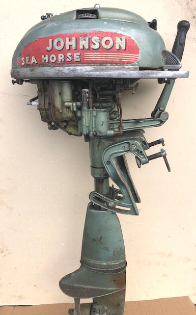
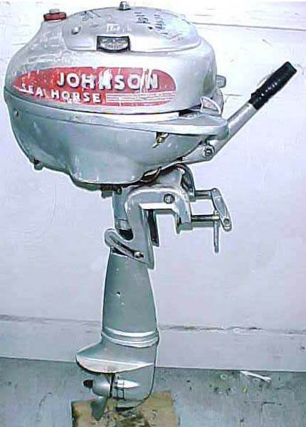
T series 2 Cycle
Outboard Motors
1941-1953
 |
Maintaining Johnson 5hp T series 2 Cycle Outboard Motors 1941-1953
|
 |
One thing that I want to convey here is that I write only on motors that I have actually worked on, and over a period of MANY years, consisting of many THOUSANDS of hours, and then much more time in maintaining/updating these articles. They are motor specific, HOWEVER if you are having a diagnosis issue, my Trouble Shooting article covers MANY more aspects that may help you diagnose your issue. CLICK HERE for access to that article.
Here I think we need to describe the differences in these models. For the most part, they are all from the same family, but with some differences. In short, it appears that the TS was the first one introduced and which later became the economy model, while at the time, the TD was an upgrade Deluxe version, then as a Post war version the TN underwent considerable improvements was the improved and the improved deluxe version.
The TS uses a rap around rope starter like many of it's predecessors.
It survived into the early Post War production apparently as a cleanup of Pre
War parts. The TD has a rewind recoil starter. Both
of these motors are direct drive and full 360 degree reverse.
Then the Post-Post-War
(1950) the TN was introduced having a neutral clutch system, activated by a lever on the top LH side of the fuel
tank, along with numerous other improvements, rubber impeller water pump
and improved starter unit and
later the ignition.
The TD used 3 small ratchet dog springs that have proven
over time to be a weak part of that starter unit. The TN uses a completely
different and more reliable starter unit, but outwardly the appearance
in not noticeable. However over time, the TN clutch system was
it's own
problems if the operator did not use common sense.
These Post-War TN Sea Horses began wearing the sea-mist green finish.
In this article, I will cover the TD series Johnson outboard motors, more specifically the TD-20 s/n 679,838 and if the stars align, (or I have a lapse of memory) then a TN-27 s/n 903,945. Then when this article was very near complete, I picked up another motor to somewhat fill in the gaps, a TN-26 s/n 843596 which is a late 1950 motor. Then another one, but a TN-28 s/n 952007 that was a mid year 1952 that needed some parts. And another TN-28 s/n 968848 that was so rusted that the powerhead was scrap, but more spare parts.
Year of Manufacture : This is shown in the chart below.
| MODEL | YEAR |
| TS-15 | 1941-1942 |
| TD-15 | 1941-1942 |
| TS-20 | 1946 |
| TD-20 | 1946 -1949 |
| TN-25-26 | 1950 -1951 |
| TN-27 | 1950 -1951 |
| TN-28 | 1952 -1953 |
These motors develop 5 hp @ 4000 RPM
Cylinders
2
Bore diameter
1.940"
Stroke 1.500"
Displacement
8.84 CI
Rope starter 11/64" dia.
64"
long
Bearings, bronze bushings, both mains & rod
Johnson Tillotson type sidedraft
carburetor with cork fuel float
High speed jet, preset 3/4 turn out
Idle jet - 3/4 turn out
Fuel capacity - 7 pints;
Run time full tank ?? hr;
Fuel mix is Oil 1/2 pt. (16:1) SAE-40 per Gal
Point gap is .020"
Plug gap .035", Champion J6C or J8C spark plug.
Flywheel key - Woodruff .153" wide x .235" thick x .603" long
Flywheel nut - 3/4" wrench
Water Cooled - eccentric cam operated piston type water pump, OR rubber vaned impeller type
Gearbox oil - 90 W gear oil
Gear Ratio - 14-25
Prop. dia. & pitch- - 2 Blade, RH, 8″ X 6″ for the TS & TD while a 8" X 7 1/2" for the TN
Shear Pin - 1/8" X 1.00" OAL, along with a rubber shock absorber hub in prop
Prop nut retainer pin - 3/32"
X 1 1/4" cotter pin
Prop nut, acorn, brass - 1/2" NF
Paint Color -- (1946 -51) Sea-Mist Green which is slightly metallic, or Sea-Horse Green (1952-53) which is a darker green shade.
Weight 41# for the TS, & 44# for the TD & TN
Similarities
: Now to delve deeper in the
differences. The TS is probably the scarcest of survival of the three, and
it has a different timing plate that, which if it is bad, the other later ones
will not fit, and CAN NOT be made to fit. The TS
and the TD use a eccentric cam operated piston type water pump that is
mounted on the prop shaft, with the water intake on the LH side of the
gearbox rear cover. The transom clamp screw handles of the TS and TD
are the simple sliding C clamp rod type, where the TN uses the newer folding
type handle. The TN uses a rubber vaned impeller mounted on top
of the gearbox. The TN neutral operation lever uses a flexible wire
cable housed inside a small copper tube, inside the steering column that in
turn releases tension on a tightly wound spring around the top of the bottom
of a 2 piece driveshaft in the gearbox.
The powerhead carburetor, clamping bracket and steering housing are pretty much the same on all models. Also the lower sheet aluminum motor cover skirt which is held on by 2 screws at the rear and another two in the front are the same for all these motors.
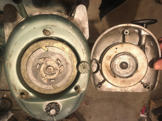
Starter : As mentioned above, the TS uses a rap around rope starter like many of it's predecessors. The TD and the TN has a rewind recoil starter, that in the manual calls it a "Rapid Recoil" style. However these two are totally different between those two as seen in the photos below.
The TD uses three starter pawl springs (#302740) which are delicate, and all 3 need to be operational simultaneously for proper functioning, however they are still available at $12.95 each.
| Here the TD recoil starter unit showing the high speed knob on the right | Here the TN recoil starter unit also showing the clutch lever on the left |
 |
 |
Flywheel :
Some
of these
flywheels (probably the TS-15s) use a standard nut which require a flywheel
puller. One
thing that you will find on the later ones will initially be when you try to remove the flywheel is that
it is not held on by a nut, but a bolt that has it's own puller built in.
When the bolt comes tight on trying to remove it, just keep turning, which outs
pressure inside popping the flywheel loose.
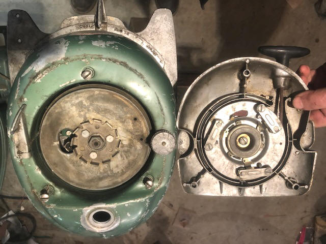
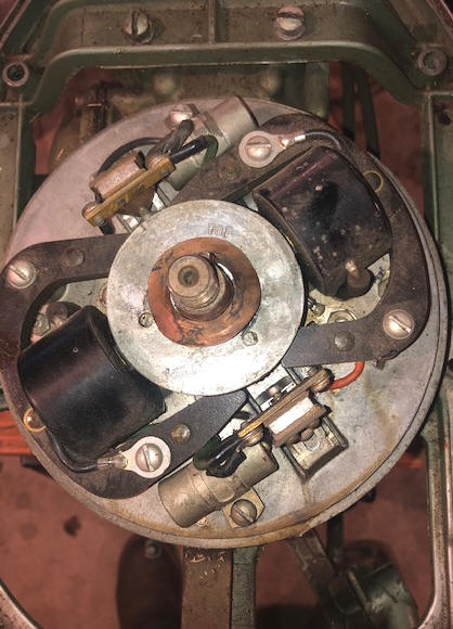
All the TSs, TDs and the TN-25/26 are different than your normal outboard motor flywheel, in that the magnets are not in the inside periphery of the flywheel, but built into a inner rotor, which has the word TOP stamped on it in ONE location. This is appears to be the location for setting the corresponding points.
Since these also have a different ignition system that also uses a different crankshaft (with size spines for a larger diameter driveshaft). This system is completely different than most, with the inner magnet rotor and "tower type points". The upper part of the crankshaft is also different in that it has a flat that operates push rods which in turn open/close the breaker points. Shown in the LH photo below, you see a 1 7/16" dia. X .025 bronze wafer washer on top of the rotor. This apparently is designed to hold the rotor down when the flywheel is installed.
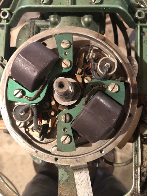
The TN-27 and 28 used a totally different flywheel and completely different points as described and shown below. Because of that, the starter assembly is also changed, even though you can't really see the outward assembled difference.
The photo below on the right showing the more modern style ignition system of the TN-27.
| Here the TS, TD, TN25 and 26 timing plate unit | Here the TN27 & 28 timing plate unit |
 |
 |
Points & Condensers : At least 90% of the time, dirty (oxidized or oil contaminated) breaker points are the no-spark problem on these motors. If you are brave, you can take the points completely apart and de-grease, and polish each contact individually. Do one set at a time, so you have a sample of how they go together, and don’t lose any of the little insulators. However, I usually just remove the set, put pressure on the push rod, and run a point file through them a few times. Reinstall and set gap to .020".
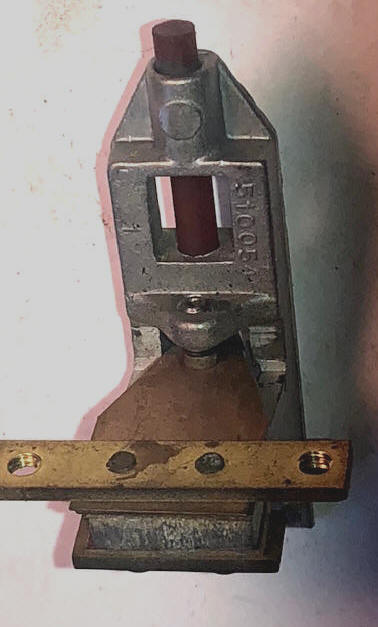
These early (TS, TD and TN-26) points, sometimes called the "tower style" or push rod style. These use -- Points assembly : #580016 - Condenser: #300153: Coil assembly: #375189. The push rod that activates these points appears to be made of round phenolic and is .153" dia. X 2.400" long with a slight radius on the outer end that contacts the spring loaded point set. On these points, there is only one locking screw when it looks close, and with no means of adjusting by a screwdriver, so I suggest that you install them, to slightly tighten this screw, then tap on the tower base, moving the "non moving contact", when you get near the setting, tighten the screw and check your setting. If you go too far, you can by using a screwdriver between the point boss and the tower, twisting it to lessen the gap. This may take a few repeated tries to get the desired setting.
In the LH photo below, the brown rod is the phenolic push rod, the wide copper strip is a spring that has the movable points attached. The solid points 1/2 is attached to the raised radiused aluminum casting which is grounded to the timing plate.
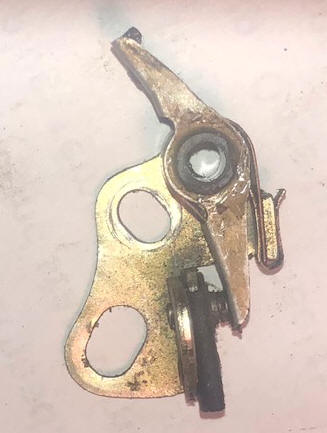
The later, (TN-27/28 as seen in the RH photo below) motors used the more conventional newer cam operated pivoting points that we now commonly see. Which are - Points: #580148 : Condenser: #580321 : Coil assembly: #580416, all which are available as of 03/2022, either factory or aftermarket by Sierra.
| Here the TS, TD , TN-25 and 26 points | Here the TN-27 & 28 points |
 |
 |
Coils : Coils for these early motors apparently are Johnson products and appear to be pretty bulletproof. Later (TN27-28 were OMC) and used on many later motors.
Timing Plate : You may find it easier for you to remove the fuel tank before removing the flywheel and get to the timing plate. You normally do not need to remove the timing plate unit unless you have to dig deeper INTO the motor.
Recommended Spark Plugs : The recommended spark plug is a Champion J6J (or the newer J6C) set at .035", however with a well used motor where the rings may be worn and may oil foul the spark plugs, some mechanics may recommend a move to a hotter plug, like the J8C. Or even open the plug gap up from the normal to .035" or even .045" which seems to allow the plug to run hotter and cleaner, especially when doing a lot of trolling.
Another thing different here for the TS and TDs, the spark plug wire at the end where it connects to the spark plug, the connection is a small metal eye that is screwed to the wire end. This eye goes UNDER the spark plug outer threaded end. Here, be sure that the small Phillips head screw on the end of the wire is tight.
Shroud /
Shirts ;
These motors use a aluminum sheet stamped wrap
around shroud that covers the lower part of the motor from the fuel tank down.
It has 2 screws on the front and 2 more on the rear. Note that there is a
slot on the RH side that accommodates the fuel shut off valve, this valve has to
be positioned to match the shroud slot. To install this shroud, it is best
to attach the LH front first, (as it has a male/female recess that the RH front
engages). The 2 rear screw attachment uses slots instead of holes, (so
this shroud can be loosened there, and be tipped down to access the spark
plugs.) Get the 2 rear ones aligned and move forward to the fuel
line valve and then the front RH screw, all the while aligning the RH front of
this shroud into the formed lip of the LH shroud. Tighten all the screws.
NOTE, if this shroud has become bent, dented, misshaped, it
needs to be reshaped as best can be to allow for a good installation.
Carburetor : This carburetor appears to have been a redesigned Tillotson side draft style. To remove this carb, it may be best to remove the fuel tank beforehand to be able to see better and gain easier access to the linkage. The outer exposed retainer 1/4" nut along with the screw on the rear are obvious. In addition, you will need to disconnect the air tube from the front of the crankcase which the idle needle is connected to, and remove the small cotter pin holding the throttle valve arm to the timing plate.
These carburetors are the same for all the T series motors, however the throttle linkage is different for the TN series.
The high speed jet is controlled by a knob protruding slightly above the fuel tank on the RH side. It also acts as a tickler choke or fuel primer when push downward.
The priming (choke) system is a downward push of the high speed knob, however it
does not prime fuel into the manifold, but into the "rotary crankshaft valve".
This plunger's material was changed from brass to stainless steel in late
production (TN28).
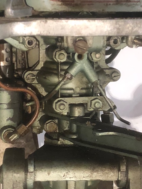
In the photo below, the low speed valve is a smallish wire type bent rod
coming off the LH front of the front of the crankcase. Once this is set, there should
be no need to readjust it, however the initial setting should be 1/2 turn out
from lightly bottomed out. The bent copper tubing is the fuel line from the fuel tank
into the carburetor.
A tip here on reinstallation of these carbs, do the carb to timing plate linkage first and then the fuel lines before you make the final carb bolt on.
| Here the low speed adjustment control protruding out on the right below the fuel tank |
 |
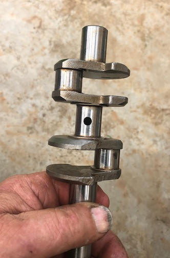
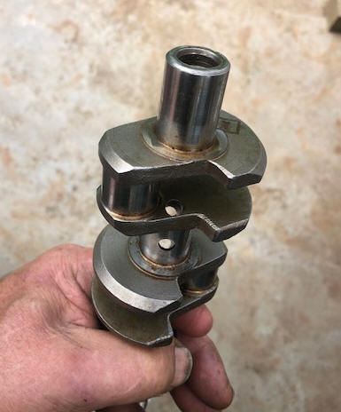
These T series motors have a totally different low speed valve than seen on most motors of this era. And I for one am a little confused, so I will quote from the owners manual. "These series of motors operate on the sane general principles as all others, however the method of crankcase induction differs in some respects. Use is made of two intake ports, that is, one built into the cylinder wall (typical 2 stroke) and is operated by movement of the piston. The other is built into the center main journal bearing, and is operated by the rotation of the crankshaft. A hole corresponding to the port (opening)in the center journal bearing, is drilled into the center journal (crankshaft which leads directly to the crankcase chamber. This arrangement is known as a rotary valve. By combining these features, it is possible to obtain highly efficient carburation at all times".
"Carburation is of the full range type, thus providing efficient carburization
at all speeds --- some departures from customary construction has been made.
Nevertheless, in that only the high speed needle and jet are built into the
carburetor body. The slow speed needle and jet are actually not part of
the carburetor proper --- this feature is part of the crankcase assembly (on the
front of the block as shown in the RH photo above), and function throughout the
entire speed range of the motor.
Since both third port and rotary valve principles are
employed, there are two independent systems of carburetion. The
carburetor itself is the conventional type --- consisting of a float chamber,
mixing chamber, throttle valve, needle for adjusting mixture and a connection to
the intake manifold. The carburetor and third port operate only at the
intermediate and high speeds and cease to function entirely at slow speeds.
Slow speed operation is maintained, however, by mixing air and gasoline in the
slow speed opening which is conducted to the crankcase chamber by way of a
rotary valve.
Carburetor adjustment is done in two steps, High speed and Slow speed. (1) Close the slow speed needle by turning it to the right until it rests gently on the needle seat, then unscrew it approximately 3/4 a turn to the left (RH photo above). (2) Close the high speed needle by turning it to the right until it rests gently on it's seat, then turn it approximately 3/4 of a turn to the left (the large knob on the top RH side of the fuel tank). (3) Start motor. (4) Operate at full speed with spark at full advance until normal motor running temperature is reached, Turn the high speed needle either to the left or right as required to obtain maximum speed. (5) Retard the spark by moving the magneto lever to a midway position. adjust the slow speed needle as required to obtain smooth and consistent running at slow speeds.
These needles should be adjusted separately and not at the same time. Once set the slow speed needle should not be required to be readjusted".
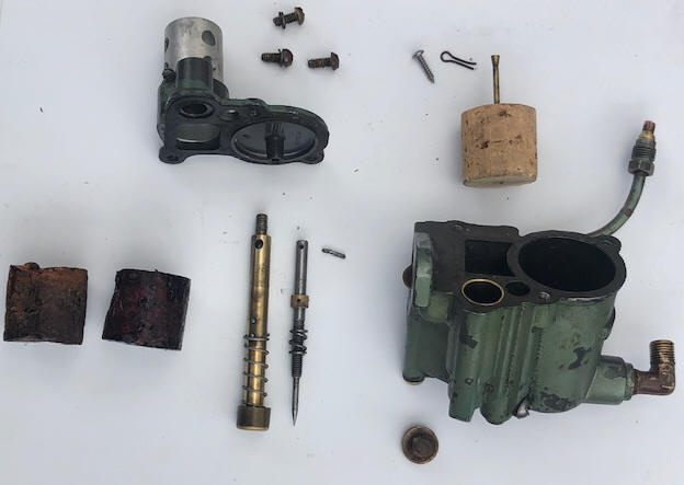
The LH photo below shows most of the disassembled carburetor parts, along with 2 bad cork floats and a new one. The RH photo below shows the start of a new cork float.
If you own one of these motors, or need to repair the carburetor, here is a VERY GOOD online illustrated article on removal, repair and reinstall Johnson H & T carburetors (Basic Carburetor Servicing Johnson H and T Series by David Poche) http://pochefamily.org/outboard/CarbService.html
| Here you see the disassembled TN carburetor, the TD only differs slightly in the linkage to the timing plate |
Here the new cork float being rough turned to size. |
 |
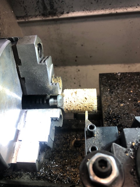 |
The carburetor cork float had shrunk and was badly distorted, (as shown in the LH photo above) so using the David Poche method, (RH photo) I made a new float on my lathe by Super Gluing the new oversize 3 or 5 gallon cork to a 5/8" nut that I eyeball centered to the cork. Then lathe turned with a VERY SHARP cutter, roughing it oversize by about .040" and then ultimately sanded it to the proper diameter using a medium/course sandpaper stapled to a small 2" wide pine board. Carb float (cork) 1.125" OD X 1.120 OAL (taken from an apparently good existing float).
One thing
that I found was that modern stopper corks seem to have a lot of cracks/holes,
so it worked out best when I applied the first few lacquer sealer coats,
then with Plastic Wood filling the holes, then lightly sanded them, and more lacquer.
Be sure that the cork float is
locked on the needle shaft but free to move vertically, otherwise they are prone
to stick (or it could be the old cork being waterlogged with gas that it will not float)
but may stay in the down position and will not be shut off and will let gas
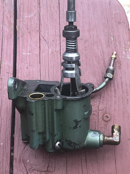
overflow out the vent hole. Also the insides of the bowl also has to be clean
and smooth. This was done by using a automotive wheel cylinder hone as
seen in the photo below. Don't over do it, just remove any roughness on
the inside so the float is free to move vertically.
| Here you see honing out any attached debris in the float bowl |
 |
These float needles work different
in that the needle protrudes through the center of the float. The needle is
reverse tapered at the bottom with a tapered triangle cone (larger at the
bottom). This cone is what shuts off the fuel flow when the cork that the needle
is attached to raises when the bowl is full. As the engine uses more fuel, the
fuel in the bowl is lowered, allowing more in. There is a large screw head plug
that this needle is inserted through from the bottom. If that needle does not
seat well in the orifice, the fuel will not shut off and overflow up and out the
tickler hole in the top of the carb. To clean this seat in the orifice, do not
use any abrasive, however I have used a Que-Tip with tooth paste on it to clean
and lightly lap that orifice.
| Here you see the crankshaft center main holes | Here the same crankshaft but photo at an angle showing the two holes from the center main into each individual cylinders |
 |
 |
Fuel Tank :
To
get
the fuel tank off, there are
two hex head bolts on each underside. Then the fuel line coupler at the
shut off valve has to also be disconnected. Also on the carburetor, a 3/8"
hex nut holding a split tongue arm that straddles the carb high speed jet knob,
has to be removed to disconnect that from the fuel tank.
Fuel Filter : There is no filters, per say, other than a very fine screen mounted inside the fuel tank attached to the upper part of the shut off valve, and another screen on the bottom of the outlet chamber of the carb's large headed screw. In your tear down, it may be a good idea to also remove the shut off valve stem and clean that seat.
Recommended
Fuel / Oil Mix :
The following is taken from these motor's
instruction manual. "Since fuel vapors are first compressed in the
crankcase of the engine, the most practical method of lubrication is
mixing the lubricating oil with the gasoline. Lubrication is
obtained as the mixture of oil and gasoline enters the crankcase and is
later transferred to the cylinders. Oil being les volatile than
gasoline, a portion of the fuel-oil mixture remains in the crankcase to
lubricate the bearings and other moving parts, The remainder
enters the cylinders with the pre-compressed charge to aid in the
lubrication of pistons and piston rings. It is extremely important
that the oil, in the amount specified, be thoroughly mixed with the
gasoline to ensure efficient operation of the motor.
Use Mobile AF or Mobile Marine No. 4 or an S.A.E. No. 40 oil
of similar character and produced by a reputable concern.
The recommended mix
is, Oil 1/2 pint (16:1) SAE-40 per Gallon of gasoline.
BE SURE IT IS THOROUGHLY MIXED."
A gallon of gas is 128 oz. A quart has 32 ounces of oil in it. So for a portable 3 gallon gas tank to fill it using the 16:1 ratio would take 24 ounces, (3/4 of a quart) of oil. To quantify this, 3 gallons of gas = 384 oz -24 oz of oil = 16-1 ratio.
The formula shown below will be on all modern 2 cycle oil sold in the last 40 years or so. On most all of the pints and quart plastic bottles of TWC-3 oils there will be a narrow clear vertical window on the edge of the bottles. On the sides of this window will have numbers representing ounces and Milliliters for other parts of the world. Or you can purchase special measuring containers showing different ratios and the amount of ounces needed.
|
FUEL MIXING TABLE |
|||||
| Gallons of Gasoline |
Gasoline to Oil Ratio |
||||
|
Ounces of Oil to be Added |
|||||
| 16:1 | 24:1 | 32:1 | 50:1 | 100:1 | |
| 1 | 8 | 5 | 4 | 3 | 2 |
| 2 | 16 | 11 | 8 | 5 | 3 |
| 3 | 24 | 16 | 12 | 8 | 4 |
| 4 | 32 | 21 | 16 | 11 | 6 |
| 5 | 40 | 27 | 20 | 13 | 7 |
| 6 | 48 | 32 | 24 | 16 | 8 |
The official OMC fuel/oil mix for most outboard motors in this year ranges has for years been 16:1 because of the bronze connecting and main bearings as compared to the newer needle or roller bearings. This means 16 parts of regular gasoline to 1 part of outboard motor oil. Remember that this was before unleaded gasoline or even possibly an octane rating that was listed at the pumps. Now the recommended fuel is 87 octane gasoline. Early on for the 2 cycle motors the recommended oil was regular automotive 30 or 40 weight motor oil.
Then the outboard industry came up with any TWC oil, which finally evolved into the latest which is TWC-3 outboard motor oil. You probably will not see much of the older TWC-2 oil out there anymore. You can spend your money and purchase OMC oil for about $7.59 a quart, or buy a name brand quart for $3.89. Sure the manufacturers want you to buy their oil, and for a new motor under warranty, it may be advisable to do so. But the consensus from many experienced boaters is to use any good brand of oil, as long as it has the TWC-3 rating, it meets or exceeds the manufacturers specifications. The TWC-3 represents, Two cycle, Water Cooled, type 3 formula. The formula 3 has decarbonizing additives designed to be more compatible with the newer non-leaded fuel.
So, from the above information, you can see that fuel and oils have changed dramatically since these motors were first brought out in 1949. In this instance, times have changed for the good, as we now have a better gasoline along with way better outboard oils. Therefore, (in my opinion), see no issue if you reduce the amount of TWC-3 Full Synthetic oil to 24-1 or even 32-1 for these motors if you are using minimally at high speeds and with it mostly for trolling.
DO NOT use oil designed for your weed whacker or chain saws as these air cooled motors run a lot hotter than the water cooled outboards. The water cooled outboards require the specially designed TWC-3 oils.
To Stop It : There is no kill button on Johnson motors up until about 1979, here you just retard the timing plate/throttle lever as far to the right to the STOP position, and the motor should die.
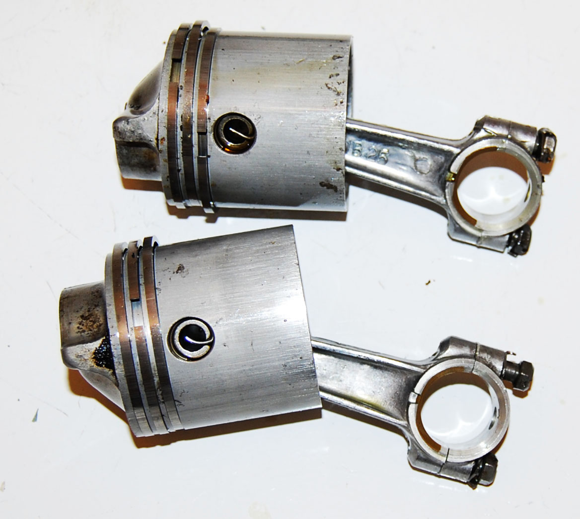
Inside the Block : Hopefully you will not have to go inside this block, but shown below are a sneak peek of the pistons with rings attached. Note - there are 3 sets of of hefty rings on each piston, and bronze connecting rod bearings.
One part that has changed over the years is the lower crankshaft seal assembly and I suspect this took place at the start of the TN series and again when the TN27-28s came into being. As a side note, I cannot find this seal in the TS or TD series motors parts list. Maybe with this rich and thick of fuel mix, they are just using the lower crankshaft shoulder as a seal ??
| Here the T series pistons with rings | |
 |
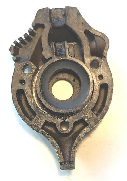
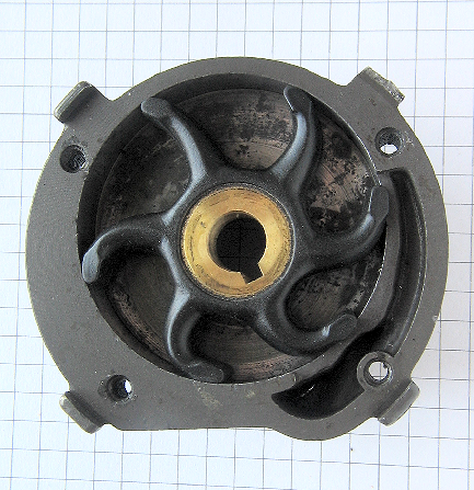
Water Cooling System : The TS and the TD use a eccentric cam operated piston type water pump that is mounted on the prop shaft, (rear of the gearbox rear cover) with the water intake on the LH side of this gearbox cover. This eccentric cam is driven off the prop shaft, driving a rubber covered osolating plunger with a stroke of about .150". As seen in the LH photo below, the pump "impeller" osolates as the prop shaft turns, forcing water up into the RH chamber, and on the upstroke the upper protruding arm helps push water up into the powerhead. You can see the intake area on the upper left edge. On the RH edge opposite the water inlet is a drain plug.
| Here the TS & TD outer water pump housing including the piston / impeller | Here the TN impeller in the upper water pump housing |
 |
 |
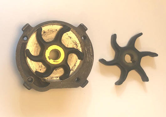
The TN uses a rubber vaned impeller type (as seen in
the RH photo above) mounted on top
of the gearbox. The
original
impeller was #375688, which occasionally can be found on eBay at a price of near
$30. However
the Sierra impeller 18-3001 (at a price of $10) can be easily modified to fit. This impeller
normally fits on the 3.0 hp (1952-1972 or the later Johnson 5.5 hp 1954-1964).
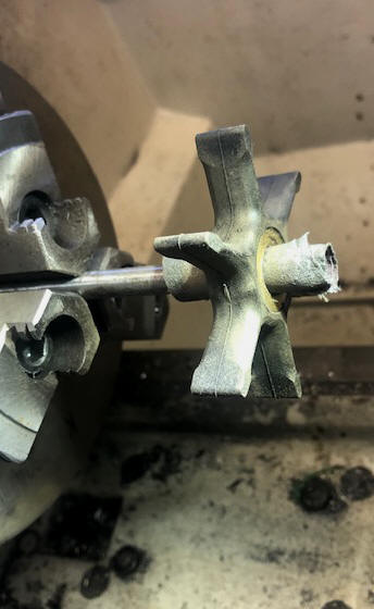
The difference is the shaft bore dia., which needs to be enlarged by .010"
up to about .440". As shown in the photo below, a 5/16" rod, split sawed
about 1" in from one end and #320 emery cloth wrapped in the slot and around it
in a metal lathe, however a electric drill would also suffice.
| Here the Sierra #18-3001 impeller hub being opened up enough to fit the TN driveshaft |
 |
One thing that was interesting on the old impeller, is that the center hub was made of nylon as compared to brass that we usually see now. The drive key is a simple round stainless steel rod .119" dia. X .312" OAL and slightly radiused on the ends, which fits into a 1/8" blind round hole in the driveshaft.
When I got around to look at the water pump, the impeller on the TN-27 had taken a set, but the interesting thing was that the leading ends of the vanes were worn considerably because of the pitting inside the aluminum pump housing. I looked around for a replacement, and even thought about modifying a later more common Johnson 3hp J series body, (which also used the same Sierra impeller) only to find they were also obsolete, and a few surviving Old New Stock, but at a price of from $70 to $144 just for this housing, with complete kits listing for only $169.99, as of 4-2022. And the outlet grommet sells for only $15.95
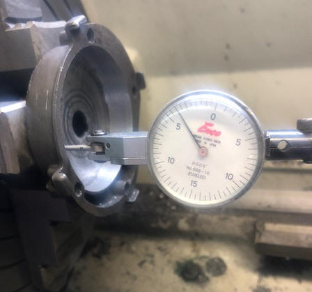
My only option here was (as I have done before) was to mount it in my metal lathe, and since the outer part of this housing is not concentric with the center shaft area, use it in a 4 jaw chuck. I had to dial it in by hand (trial and error for an hour) until I finally got it to within .004" of being true (a sheet of newspaper is about .003"). I then machined out about .010" to .012" in order to clean it up. I could not get the inner face flat enough in the chuck to re-surface it also, and did not really want to deepen that area very much anyway. I had to compromise as to not go too far and ruin what I had. Then by using 300 grit emery cloth as it was spinning to smooth out the cut, it came out acceptable as compared to what was originally there upon my disassembly.
| Here the TN water pump housing being dialed in |
 |
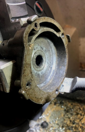
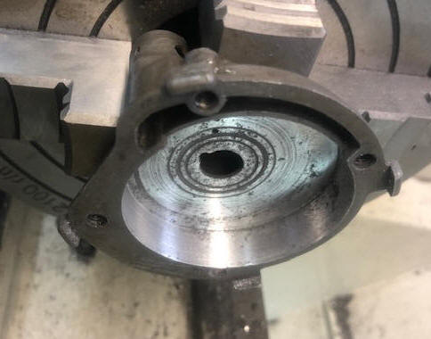
In the photos below, while still in the lathe, you can see the improvement. The circular scoring in the center should be of little consequences as this is at the hub area and not out on the vanes.
| Here the TN water pump housing before machining | Here the TN water pump housing after machining |
 |
 |
| Here the re-machined TN water pump housing and new impeller installed, with the old one shown at the side |
 |
The TN series (as compared to the TS an d TD) water intake was moved to a screened slot in the front of the exhaust leg protruding downward right behind the prop, like many of the newer Johnson models used clear up until the late 1980s.
Tell Tail Water Discharge: There is a indicator of overboard water when the water pump is operating properly. There should be a small stream of water exiting from a hole drilled in the water line elbow coming from the steering column base to the cylinder block.
Thermostat : These motors were designed without a thermostat.
Tiller Handle & Grip : One important thing for these models (and the factory recommends to not do) is to try to tilt the motor up by using the tiller handle, but to reach to the rear and lift the motor from that area, otherwise you MAY break the handle bracket off at the front lower part of the front of the powerhead (as encountered below).
On the outer end of the cast aluminum tiller handle is a bicycle type rubber grip handle. These can be replaced by a aftermarket reproduction which sells for $15. They are available on eBay under the title of "Vintage Large JOHNSON Outboard Motor handle grip 1935-50 DT AT TN TD TS DS" https://www.ebay.com/itm/133903082985
Clamp / Tilt Bracket ; The transom clamp screw handles of the TS and TD are the simple sliding C clamp rod type, where the TN uses the newer folding type handle. At the lower part of the outside bracket, is what the factory calls "thrust socket adjustment". This consists of a radiused 1/2 socket that the driveshaft casting rests into during steering. It can be adjusted to match the boat's transom angle by the medium sized wing nut that secures the bracket to the motor. In this system, is also incorporated a reverse anti kick up when the motor is rotated 180 degrees, which engages the lip of the upper gearcase housing as seen in the RH photo below.
Tiller Handle
:
This
motor came with the tiller handle broken off at the base of the powerhead.
After considerable looking, I did find a used assembly at a decent price.
This aluminum handle unit is made as part of the steering column #375-727 and
officially called the driveshaft casing. It also
had a small broken part, but the issue was how do I get it apart (after 70 years
of abuse) and not damage anything beyond repair?
The upper gearcase housing #302315 on this model is clamped (by one
5/16"
stainless steel oval head screw) onto a brass driveshaft tube. The screw head showed
signs of someone in the past trying to loosen it. My method was to pound
on the screw head a few times with a hammer, trying to break any seizure bond.
Then I got a large well fitting screwdriver and a 12" Crescent wrench, then
heating both sides of this aluminum case (screw head and open end of the screw)
with my Oxy/Acetylene torch hot enough that I did not want to touch it for more
than a second or so, almost to where the paint was starting to discolor.
I then sprayed WD-40 on both ends of the screw. Now securing the whole
unit in a large vise, placing the screwdriver in the slot, I rapped it rather
hard a few times , then with the crescent wrench for leverage on the screwdriver
handle, proceed to try to unscrew it. My method worked better than I had
anticipated.
This 1 5/8" brass tube is apparently pressed, or shrunk into the aluminum pivot base and handle unit. The clamping bracket/swivel unit then slides up and over this upper tiller pivot shaft which has a split brass bushing in between as a adjustable bushing tightened by a cross screw.
Then to disassemble the rest down to the bare tiller arm and the brass shaft and to clean them up.
Now do the same on my broken motor part and then reassemble with the good part onto the motor. Here tearing down the unbroken part was a learning experience so that I did not damage the piece needed for the reassembly. As on this one I tried it without heat and it just thumbed it's nose at me.
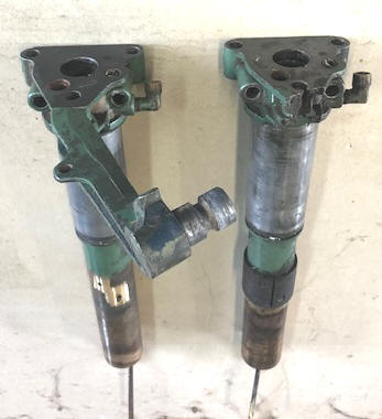
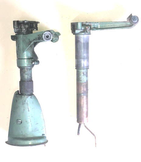
On this used part, the steering thrust lining #41-63 (made of Bakelite) the 2 attachment rivets had became undone. I made new rivets of aluminum but in trying to get them inside the tubing AND riveted, I broke the lining. OK move on to plan B, which was to epoxy it back in place, (using my new rivets but in from the outside as locators). Once the epoxy was on and the parts aligned, I used a 9" ball bungee cord to secure the liner in place while the epoxy cured.
| Here you see the top view of the steering column (Good - Broken) | Here you see the broken, and good part stripped down |
 |
 |
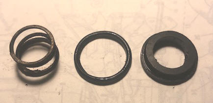
At the time you remove this unit from the powerhead, be very careful and not loose the lower crankshaft seal assembly that exists in the recess on the top of this handle unit where it mates to the powerhead. It is a black ceramic seal .965" dia. X .225" thick with a .590" dia. hole in the center, that has a lip of this diameter on the outer upper circumference, which below the lip, a 15/16" X .093 thick O-Ring is located as a outer seal in this pocket to the housing, which also has a .725" dia. X .500" tall X .056" dia. wire coil spring which puts upward pressure of the seal onto the bottom of the crankshaft.
Before I reassembled this seal, the ceramic had some slight grooves worn in it and since I was using a different housing, maybe it would be beneficial to lap the upper seal contact surface. Using a small section of 1/8" sheet aluminum, and some FINE valve grinding lapping compound (and a squirt of WD-40 for lubricant), it did not take long to get a new unscored surface.
While going to all this effort, and considering that the O-Ring seal had hardened considerably, that was also replaced.
| Here you see the lower crankshaft seal parts |
 |
Tilt Lock : These motors have no up tilt lock position, other than tightening of the hinge pivot screw of the clamping bracket.
Drive Shaft Differences : Obviously the TS and TD driveshafts are different than the TN series because of the water pump and the clutch on the TNs and will not interchange. But from personal experience during writing this article, the TN-25/26 has a different driveshaft than the TN-27/28,so not all TNs are the same, (learned the hard way).
Shaft Length : These motors were also available in standard, (15") or long (20") shaft lengths. If no other letter after the model, then it is a standard length shaft, but if a long shaft, being identifiable by adding to the the model number, the letter L added to the end, but before the year date code numbers.
Removing the Lower Unit : The TS and TD motors only require unbolting the lower unit from the upper gearcase housing where the lower unit and driveshaft can then be withdrawn. However if it is like most of the later models, the drive shaft will easily come out of the unit, letting oil pour out.
The TN requires additional procedures, (1) The neutral clutch cable has to be disconnected under the LH side of the fuel tank. Then the 4 bolts in from the bottom of the anti-cavitation plate. The clutch cable comes out as you withdraw the lower unit.
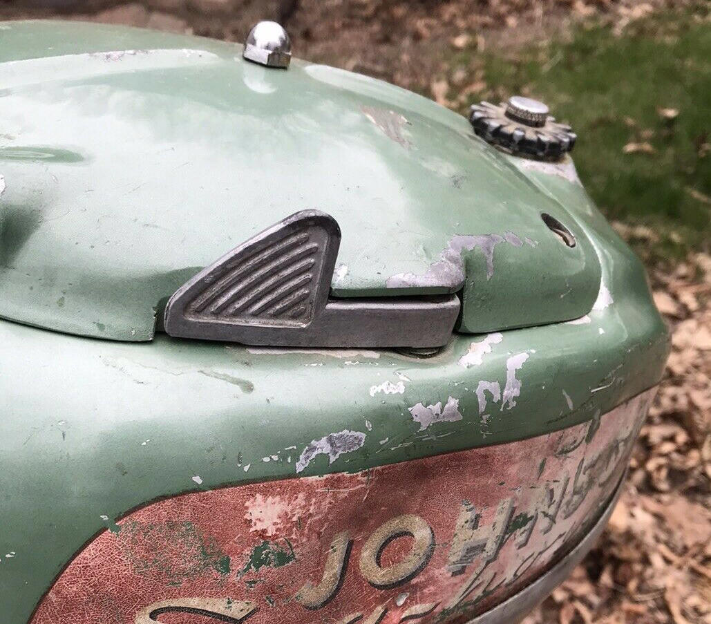
Clutch : The TS and TD are direct drive and have no clutch, but the later TN does. This is operated by a lever on the top LH side of the fuel tank, from which a small steel cable (running inside a copper tube) into the gearbox. This model uses two drive shafts, (1) a upper and the other inside the gearbox, with a tightly wound square coil spring connecting around both as a slip coupler.
It has been observed that apparently this clutch system had issues, OR the operators (DIY) mechanics did not understand, as on a number of the TNs that I have picked up from garage/estate sales, the clutch levers were missing. This did not effect the operation of the motor, only made it in gear all the time like the TS and TDs.
The control cable to the clutch unit is a 1/16" galvanized cable (available at a good hardware store for $.31 a foot), where 3 feet will suffice with about 5" left over. You will need to salvage the bottom ball and re-solder it to that end. The top end needs to be trimmed to length of the original and soldered and smoothed so that it will feed up through the tube to and into the lever assembly linkage arm.
| Here you see the neutral clutch lever (Fig. 11) |
 |
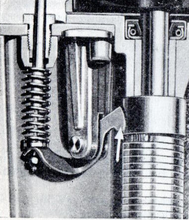
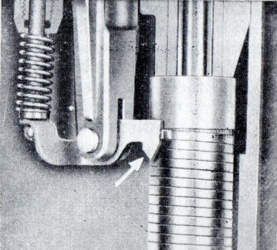
As noted in the owners manual, "The neutral clutch consists of steel bushing keyed to the lower driveshaft , an accurately ground steel sleeve driven by the upper driveshaft and spring which is coiled around both the steel sleeve and the bushing.
Propeller drive is accomplished by gripping effect of the clutch spring on the sleeve and bushing created during operation of the motor (Fig. 20).
When set in neutral operation, the latch is lowered (Fig. 21) by the neutral control lever (Fig. 11 as seen in the photo above) to obstruct rotation of the clutch spring. This action causes the spring to unwind and to subsequently release it's grip on the steel sleeve and bushing to permit "slippage" between the upper and lower drive shafts - neutral. When operating "in gear," the latch is lifted (Fig. 20) by moving the neutral control lever to running position (Fig. 21) to resume rotating of the clutch spring and it's grip on both the steel sleeve and bushing. Rotation causes the spring to "wind up" to increase it's grip as the motor speeds up."
| Here the TN clutch is disengaged as described in Fig. 20 | Here the TN clutch is engaged in a neutral position as described in Fig.21 |
 |
 |
Gearbox : Here, the gearbox oil also lubricates the above mentioned clutch unit, therefore if you are going to get into the water pump, or go into the gearbox, it may be best to drain the gear oil out beforehand. The reason you need to drain it when servicing the water pump, ON THIS MODEL, the 4 screws holding the water pump housing to the spacer above the gearbox has those screws going in from below, (inside the gearbox oil reservoir), not the top of the water pump like most are.
Replacing the Lower Unit : The TS and TD are a bit simpler, as JUST the driveshaft needs to be aligned with the splines of the crankshaft simultaneously with the water tube as the lower unit is slid up and in place.
The TN requires additional procedures, (1) The neutral clutch cable has to be threaded up in the small copper tube at the bottom of the steering column/gearcase housing, that leads up inside the lower block, then into another copper tube goes up and under the fuel tank mounting plate, where it attaches to the clutch lever shaft. This cable has to be threaded up far enough that it protrudes at the clutch base upon assembly. If it does not, you will need to use needle nose pliers and at the bottom where the cable exits the gearbox, grip the cable and pull it up from inside the gearbox until it stops.
Now proceed as with the TS and TD series, only now you HAVE 3 ENTITIES to contend with all at the same time.
Prop
:
These
three models use different props, the TS and TD are different and non
interchangeable with the TN.
The TS and TD
prop uses a shear pin 1/8" (.125") dia. X 1.00" overall length.
For these, the prop dia. and pitch are 8″ X 6″ - 2 Blade, LH rotation, for the TN, a 8" X 7 1/2".
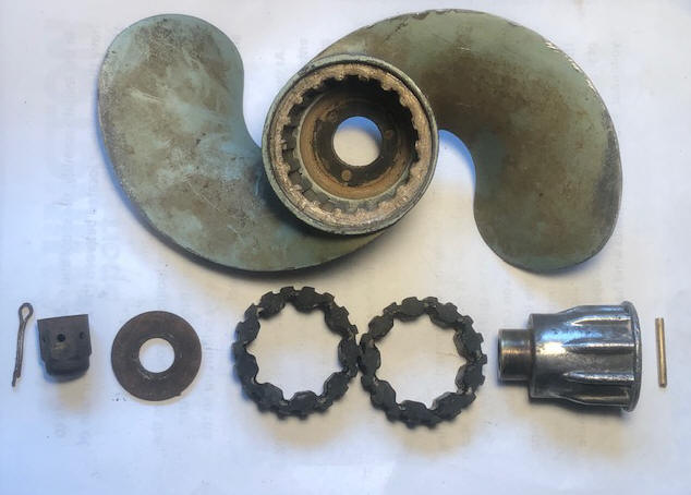
Inside the prop hub is a rubber shock absorbing hub.
In the photo below, you will see all the components
associated with the TS and TD prop. This rubber shock absorber is made in two
sections, one stacked on top of the other in the prop, (I have seen others that
are a single unit). To remove
this rubber ring, use a small screwdriver, work it in/under the ring and work
your way around the grooves until it is all loose. Clean them, AND
the prop recess, and apply a very light coating of waterproof grease on the prop
recess and the inner/outer parts of the rubber rings. Later small motors
may also use this same rings, but instead of two short ones, they use one long
one.
| Here you see the TS & TD prop & it's other component parts |
 |
Prop Nut For TS & TD: The prop- shaft is 1/2" with the nut threads being 1/2" NF. The nut is a non standard NF acorn nut but made of brass, with 3/32" holes on each flat. The non standard part of this nut is that it is deeper than the regular ones to accommodate the length of the shaft that may protrude. The cotter pin is 1 1/4" OAL.
The TN prop is totally different with there not being a shear pin, but a DRIVE pin at the rear of the prop. Apparently there is no need for a shear pin since this motor uses the spring type slip clutch.
| Here you see the TN prop & it's other component parts |
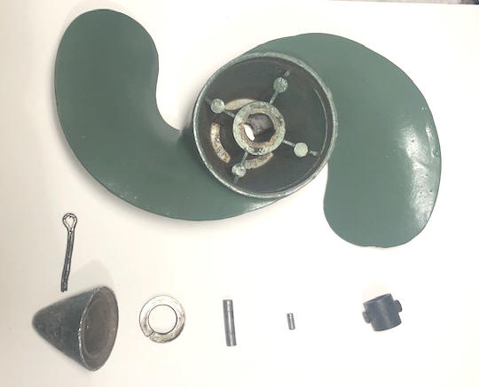 |
Prop Nut For TN : The prop- shaft is 1/2" with the nut threads being 1/2" NF. The nut is a aluminum cone type, with a 1/2" lock washer between it and the rear of the prop. The cotter pin is 1 1/2" OAL.
Other Issues With This Motor: As mentioned above, this TN-27 motor came along as spare parts for the TD-20 that I purchased at an estate sale. Unknown to me, or the seller, not all parts would interchange. This TN-27 had a broken (missing) tiller handle, no lower unit, no lower side skirts, a badly dented fuel tank on the LH side, and no fuel cap. But compression was very good, the starter worked, and carburetor was there and looked complete. That is why I started to look for enough used parts to assemble it to be a runner again.
I found a TN lower unit on eBay that was mismarked as a TD for $50 plus
shipping. I did find all the other needed parts (I thought) and
bought carb parts. OK now with all the
missing/broken parts located and on the motor, there emerged a problem.
Everything thing was coming together, until when I tried to
install the lower unit. I could not get the driveshaft splines to engage
into the motor's mating female crankshaft splines up inside the housing.
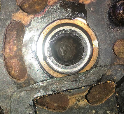
Finally, after fighting it for too long, I pulled the power head and got a look
at the bottom of the crankshaft. NO, or minimal obliterated splines. The hole was smaller
than the replacement driveshaft, but had no lower splines, a few up deep however. It appears that possibly the
driveshaft spline area was broken off inside the crankshaft. There
was some evidence of someone had tried to drill it out. But with me not knowing
the situation, and not being able to see in there very well, I need to
investigate farther.
| Here you see the lower part of the TN crankshaft |
 |
I am not really sure what happened here, but the new hole appears to slightly larger than the small diameter of the splines on the shaft. And if I could get it cleaned up, the depth of the splines would be of questionable value. As it stands now, I have $208 in this FREE motor, and it still needs a lot of TLC to clean it up, do body work on the fuel tank and skirts. So as it looks now, I may have to find a junker to cannibalize for the crankshaft, then Bondo the gas tank then new paint and decals. Is it worth that much more, maybe just another challenge or expensive yard art?
OK, 2 weeks later, I did locate a seized up TN-28 for parts for $10 that was also missing the starter unit, flywheel and coils. When I got the crankshaft removed from this 28 block, it had a considerable amount of rust on 2 of the rod journals, but since the bearings were bronze inserts, I was hopeful that it could be made to be usable.
Since this new donor motor had a better midsection clamping brackets, why not pick and choose the best parts? And I had already rebuilt the water pump on the #1 motor, so use that lower unit assembly.
Now another surprise, this online purchased driveshaft splines would not go into
the "new" crankshaft splines (too big). It appears that the used lower
unit that I got online may have been off a earlier motor (TN-25 or26) as that
shaft was 1/2" diameter at the splines. But since I have never been into
one of those models, I was just guessing (proved to be true later when I
acquired a TN-26).
OK, I got both lower units apart. In the photo below, the upper
shaft is off a known TN-28, the lower one has to be off a TN-25 or 26.
Both are the same (7/16" diameter) for the lower part at the clutch and water
pump, above that on the 25 it is 1/2" diameter along with the splines. The
upper one in the photo (28) shaft is 7/16" all the way through, using a 7/16"
spline. There is also a difference on the upper spline end, which relates
to different lower crankshaft seals. The seal was bad on the new
cannibalized 28, so I reverted back to using the original seal of the 27 that I
had to start with on the 27 midsection. I removed the spring thrust
bushing off the 28 as I was not sure if it would interfere the 27 seal in the
midsection housing.
I should have tumbled when I got the online lower unit as the paint color was a slight different shade of metallic green. But being a greenhorn with this model, I just ASSUMED !! I then find they changed the color of Johnsons from (1946 -51) Sea-Mist Green, to Sea-Horse Green (1952-53) which is a darker shade.
| Here, it is hard to see, but the bottom driveshaft is larger about 3/4" above the impeller key hole on the left |
 |
In case I got you got lost, the gearbox and water pump are the same, just the driveshaft and crankshaft are different (WHY, possibly a carryover if the TD ignition parts into the TN-25/26).
More online research and I happened onto a New Old Stock TN-27/28 #376041 crankshaft (60 years old) and the correct one for $40. As a note, the TN-25/26 driveshaft is #302317.
I am so deep in this now, maybe I had better go whole hog and get it and at least have a runnable motor. This crankshaft is again for a 7/16" driveshaft and the water pump impeller is in good shape, it just needs the aluminum housing lathe turned to clean up inner periphery pitting, as I had done on the previous one. So when I am done, I will also have a rebuilt TN-25/26 lower unit that I can swap or sell.
Twisted Off Head Bolts : Now to tear the powerhead apart and replace the crankshaft. OH SHIT. While prepping to tear it down, I noticed some salt type crud creeping out between the head gasket. OK, pull it off also. But in doing so, 5 of the 10 head bolts twisted off in the block and one of the in take manifold screws,1/2 of the screw slotted head popped off, meaning get out the Dremel tool and a cut off stone to cut the screw off under the head.
I
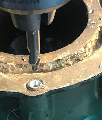
then tore the powerhead apart to be able to install the new crankshaft. The stripped block was put in a large milling
vise on my milling machine, the center of the broken bolts were eyeballed and the table locked, using a starter
center drill, then using a 3/16" stub drill to drill
through the seized bolt. Ideally I wanted the holes to be slightly offset.
Because then I using a Dremel Tool and a 1/8" carbide cutter, by go inside the
hole, and cutting away the thick side of this broken bolt, I could (sometimes if
I was lucky) take it out in 1/2s.
Then I cleaned the holes up with a
1/4" X 20 TPI 2 flute tap (2 flute because a 4 flute may not follow missing
threads as good).
I just hate it when there are that many.
| Here you see the center drill | Here you see the clean up drill | Here you see the finished hole |
 |
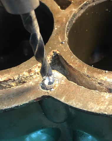 |
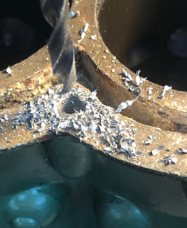 |
Now, after all the broken threads have been removed, on the holes that were seized, my options were either Heli-Coil the hole back to 1/4 x 20 threads, or if there is a substantial amount of threads left, I lightly grease the threads (a light oil will not do) on a new bolt, then using a guesstimate amount of JB Weld in the damaged thread side of the holes and screw the bolt in and bottom out in the hole, forcing the epoxy out into the cavity of the missing threads. Let them set for 6-7 hours and remove the bolts before the epoxy is totally cured, just in case the grease did not totally stop the bolt threads from being unremovable. Clean them up again with the tap and you are ready to go.
The light grease makes for a non stick bolt that can (should be) readily be removed. This then gives me a 100% thread contact.
Then the block and head
surfaces were somewhat corroded, requiring resurfacing. Here I used my
son's 4" stationary belt sander with 120 grit, which quickly cleaned them up as
seen in the LH photo below.
In the RH photo below, shown are 2 non broken head bolts of
the total 10 (5 that twisted off). Also 2 broken ones, and 2 more of
partial threads that were removed from the drilled out hole.
| Here you see the block and head after resurfacing | Here you see the broken head bolts |
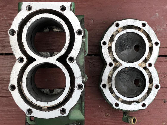 |
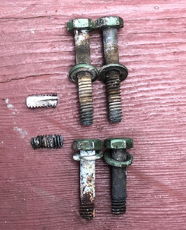 |
Reassemble Powerhead
:
Be sure that you install the
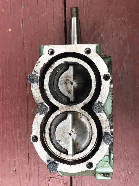
pistons in the block correctly. The intake ports may not be where you think, they are the
side of the cylinders where there is only one set of ports, (these ports supply
fuel mix from the initial intake ports through the crankcase and the bypass.)
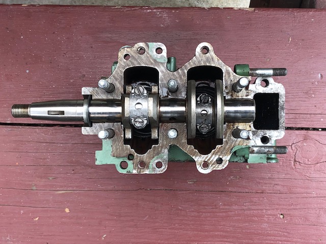
The connecting rod cap bolt heads are secured by a thin metal ear
type lock.
The compression was good, but upon tearing it down, I am glad as
the cylinders needed honing, as there was numerous small pitting.
In reassembling this motor, the gas tank mounting plate has to go
on and bolted down onto the block BEFORE the timing plate is installed.
In the RH photo below, you see the 5 temporary new head bolts that have been threaded back in the holes that are waiting until the JB Weld epoxy becomes hard enough to remove them, but not hard enough to seize them IF the grease did not do a thorough job.
|
Here you see the new crankshaft & connecting rod caps installed |
Here you see the pistons installed |
 |
 |
Then since I have not been able to find a gasket set, (but a head gasket is available) I could possibly salvage the head gasket, but why cut corners at this stage of the game. However, I could not find the others, which I had to make of bulk gasket material. It was then a challenge to assemble the powerhead to the midsection and not disrupt the exhaust manifold gasket.
One thing that is somewhat different here, under the timing plate and on top of
the support bracket are (4) 1/4" slotted head fillister screws that hold the
plate onto the block. Most all the other screws/bolts use a washer either a flat
or lock one. BUT NOT ON THESE, as if you do, add a washer), the timing plate will not rotate
(BINDS) if the washers are there.
When finished, this TN-27 motor will be made up from parts off 5 different motors. .
This Page Under Construction
Copyright © 2022 LeeRoy Wisner All Rights Reserved
Originated 02-04-2013, Last updated
07-21-2022
to contact the author click here