| Here is the air chamber with part numbers |
|
|
|
Crossman Model
1400
|
TIPS ON FIREARMS REPAIR
This air rifle is long obsolete, being a pump up version, made from 1968 to 1978, but was an improved version of the previous model 140. With that said, probably most of this information may be useful for the model 140, whereas the main difference was that the140 used a totally different safety and simple stamped steel trigger guard.
On this gun, the lady who was using it to shoot starlings trying to make a nest
in her garage, when it lost power, her husband thought it may have needed to be oiled, NO, as liberal
oiling just flushes debris inside and makes things worse. I felt sorry for
her, and her husband's deteriorated physical condition
limited his repair of the building. My accepting this repair was a BIG MISTAKE on my part. Soft
hearted me, knew better, but, well just one more time, and after I got the gun, I could not find
my old gunsmithing parts list, or any real
usable information available on the
internet. Since no usable exploded views are available, my nomenclature
may not match the factory's.
I did find a "Repair Kit" on the internet for $20, however when it
came, no instructions, and some of the O-Ring seals were not there. Hence
a trip to the local True Value hardware store for doing a comparison of the old
ones to acquire the ones needed to do the complete job. And I thought this "kit" would have included a new
front hard Nylon check valve.
Thankfully the original one in the gun was still usable.
Disassembly was pretty straight forward, using a screwdriver, punch, hammer, pliers and a 3/8" rod about 24" long to drive out the valve assembly. A suggestion, is to use your cell phone camera to take photos for the reassembly, as a couple of internal parts that have threaded holes could be flip-flopped.
The first issue was how to remove the safety lever, as that has to come out
first to be able to remove the stock(hangs outside and below the stock). This lever is large and rotates
within the trigger housing assembly. It was
held in by a large spring loaded plunger inside the front of the trigger guard
bow.
OK, I got a small screwdriver and thankfully the hole on the LH side was large
enough and by rotating the lever just right, was able to depress this plunger enough to remove the safety lever out
on the RH side.
After all the screws were removed, I had to use a 3/8" steel rod to
go in from the rear of the main air tube unit and drive the valve chamber out
the front.
This air system works backwards from what you would think, as it does
not need to be manually cocked. The sear (#140-017) is always spring loaded against the trigger,
and the air chamber/valve system also has a spring against the internal Nylon
front check valve (1400A-029). The rear seal unit (140-070) is a small
brass circular cup with a O-Ring inside and outside,
this outside O-Ring is (140-058). O-Ring (130-034) is just a seal between
the front and rear halves of the air chamber. Number (140-004) is the rear
half of the air chamber. The sear is a large
cylindrical block with a hollow rear which a spring is located in. This
sear is simply held rearward against the trigger, and a sear rod slides inside a
cylindrical bushing screwed to the outside air tube, all being held against the
rear seal cup that is under spring pressure.
The whole air chamber assembly is #140-071, but is obsolete.
| Here is the air chamber with part numbers |
|
|
At rest, everything has spring tension from the rear holding the rear seal unit forward and secure. When pumped up and the trigger is pulled, the rear spring pressure is released by pulling the trigger, allowing a internal rod to move rearward, which then releases the trapped pumped up air, which is then directed out the escape hole and into the barrel chamber and into the bolt head hole behind the pellet.
The rear seal unit being the small brass circular cup with a O-Ring outside and a smaller one inside, AND getting this old inner O-Ring out can be a chore. But by using a knife point or other sharp instrument, you need to get in behind this O-Ring and pry it out. You may have to cut it in two pieces, while at the same time trying to not damage the inner O-Ring cavity.
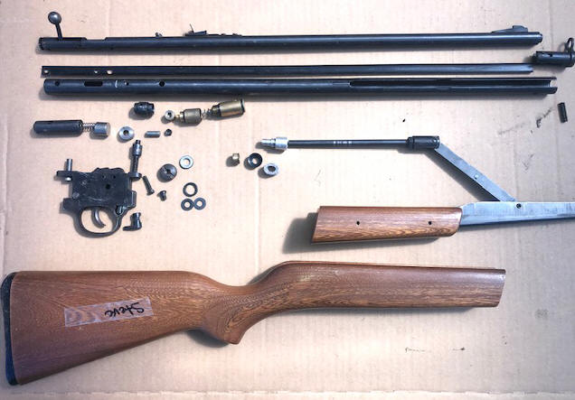
| Here is the disassembled gun laid out close to the positions they came from |
 |
Disassembly of the piston head was something else as it's construction was not anywhere what I was expecting. I was assuming that the piston rod rear end was threaded into, and retaining the aluminum head and cup somehow.
Boy was I wrong. Initially I tried to unscrew the rod from the aluminum head, but it did not want to budge. OK, it had to be Lock Tited in place, so I heated it up with a propane torch, tightened the rod in my lathe chuck and with a pliers promptly proceeded to twist the end of the steel rod off inside the aluminum head. I assumed that the aluminum head was made in a couple of pieces which slid over the rod and screwed into the brass end plug that was inside and retaining the cup. WRONG. And of course this now broken piston/rod part was long obsolete.
How do I get the cup and felt wiper off? OK, I used my knife and cut the
old cup into enough pieces to be able to see what was there. But still not
giving me a clue. OK, now the brass end had to be threaded on, so
back in the lathe chuck and under pressure, this bushing rotated, but did not screw off. After more twisting and
forcing it out, it was
pressed onto the slightly tapered aluminum head end.
Since it was obsolete, I had to devise a method of repairing it.
This involved to drill out the broken threaded rod end out of the
aluminum head. My calculating said it probably had to be 1/4", as the rod
was 5/16" and larger than the broken off end. OK, I drilled it out to
.150, the right
size for cleaning out this broken off part while still leaving a few threads if
it was threaded. My idea was to clean it up and re-tapping it if needed. But I
could not get any of this broken part
to come out even after drilling it. So I resorted to my trusty Dremel tool and carbide dental burrs,
and by going inside my drilled hole, I cut through this in 2 opposing places. Then using an ice pick, I
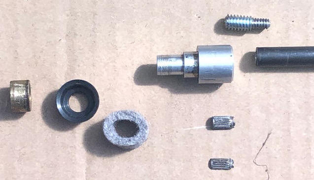
got the two pieces out. Surprise, they were not threaded in, but pressed
in as seen of the 2 knurled pieces shown in the photo below. However the
hole was the right size to be tapped out to 1/4" X 20.
Now I made a double ended threaded dual diameter adapter (1/4 X 20
on the large end and 10 X 24 on the small end). Then drilled and tapped both the
head and rod to match this adapter. Then after installing, I Lock Tited these together.
| Here is the piston head unit, showing the new threaded adapter in the upper right. But not shown here should be a washer between the wiper and the cup. |
 |
Now comes reassembly. But at my age of 84, and my fuzzy memory, along with the time from start to finish of this project, I again went to the internet to find a exploded view diagram, but as you can see from it below, it was rather fuzzy, being taken off a small photo. They must want to sell you the good copy (which I cannot find).
| Here is the best exploded views that i could find, rather fuzzy because of the small original photo |
|
|
One thing to be sure to do is on the small short hollow
rubber air passage tube that connects the air chamber to the barrel, INSIDE this
tube is a small hollow metal flanged insert. This insert has to go back into
the new yellow Nylon tube (hat type insert with the flange down), otherwise the air will leak
out and not be directed into the barrel.
On this reassembly, I will bet that you will not get it right the first time. Either you got something together wrong, a seal slipped at the last second you missed the part as mentioned in the sentence above, OR you just plain screwed up. Remember that on these, no oiling is required, except on the piston wiper.
However, it might be prudent to try it before you put the safety back in and the stock on.
The author does not have an
The author does not have any source of parts for any of the firearms listed above
Copyright
© 2021 - 2023 LeeRoy Wisner All Rights Reserved
Back to the Main Ramblings
Page
Originated 05-22-21 Last updated
06-07-2021
Contact the author
Ne