| Below are both the hammer model 94 & the hammerless 220 shotgun for comparision |
Savage 94B
Savage 220
|
|
|
|
Savage
Model 219/220
|
FIREARMS INFORMATION
General Information : These series of guns are basically a hammerless version of the popular model 94 single shot hammer type shotgun, with many parts interchangeable. Information available says they were made from 1938 to 1965 in four different variations/series. The model 219 was a rifle made in 22 Hornet, 25-20, 32-20 and 30-30, with probably the 30-30 the most popular. While the companion model 220 shotgun was made in 410, 28 ga, 20 ga, 16 ga, and 12ga. There was also a 220P and a 220AC. These were simply regular shotguns that had factory installed Polly Choke for the "P", or Savage Accura Choke for the "AC".
You could even get combo guns with both rifle AND shotgun barrels. The rifle frame has a much smaller firing pin to facilitate firing of the rifle primers, so when the gun was a combo, the rifle receiver was used instead of the much larger firing pin of the shotgun. For this combo guns using the small firing pin, they seemed to function OK, however not ideal.
For simplicity here in the information section, I will only list the more popular shotgun variations, however the rifle variations follow the same suffix letter pattern. These include the original 220, then a 220A, 220B, 220L and a 220LD, and very little info on the 220 D. The 220 and 220A used an in-line heavy mainspring activated firing pin. The 220 and 220A were very similar EXCEPT the 220A used a different firing pin, sear and trigger.
I have not been able to find information designating when each suffix series was introduced, EXCEPT what I gleaned from The Blue Book of Gun Values. The 220 was made a year earlier starting in 1937. Both the 219 and 220 ceased production during WWII. I have no information on the 219A/220A. And I suspect the 219B/220B came out after the war (1946) when the factory moved to Chicopee Falls Mass. Then there was the 219C/220C. The 219L/220L was made only from 1965 to 1967.
The 220C was a totally different internal design using a pivoting internal hammer, and the factory had a note on the bottom of the parts page for the 219C and 220C "It is not our policy to fit interchangeable barrels of different calibers or gauges on these models". Which tells me the newer variations did not have strong enough hammer/firing pin fall for the rifle firing pin to ignite the shotgun primer, and the larger shotgun firing pin does not dent the rifle primer effectively.
The last versions, 220L and 220LD was a totally different frame utilizing similarities of the then current model 940 shotgun which used a side lever to open the gun instead of the old style top lever. They also used a different internal pivoting hammer. The trigger housing assembly was a sheet metal "slide in" unit that had to use "SLAVE PINS" to assemble it into the frame. The only thing I can see different between the L and LD series is the buttstock and frame, which tells me that the LD was probably a Deluxe version.
On many of these it is hard to identify the suffix versions without removing the buttstock.
There are Model 219's, 219B's
219C's and 219L's - the Model 220 has a similar, but non-identical progression of
improved models.
The earliest 219's and 220's were striker-fired, and were re-cocked
by the opening action of the top lever, which incidentally released the barrel
lock so the barrel could be swung open, and trip the shell ejector.
Any early or later 219/219B/219C/219L/220 rifle or shotgun barrel
will fit and operate just fine in the early 219/220 guns.
Then, Savage changed the internal design, from a striker to a
concealed hammer - which the operation of the top lever no longer was able to
re-cock. So, on all subsequent models, there is a cocking lever
inside the front of the action body, which lies alongside the barrel's locking
lug when the gun is closed, or in the firing position.
The cocking lever/arm is raised, re-cocking the gun, only when the
barrel is swung open (not by the top lever opening) - by a spring-loaded stud
located in the side of the later model's barrel's locking lug(s). These
guns are the 219B/219C/219L, and later 220's. These later guns ergo
require also a later barrel, WITH the cocking lug - which is absent on earlier
barrels. The early, no-cocking lug barrels will not re-cock the later guns
- burdensome, to say the least.
The easiest way to check YOUR gun, is to remove the barrel and peek
inside the right side action wall, to see if it has a cocking lever there.
If it has one, the gun needs a barrel with a cocking stud. If it has none,
the gun can use any barrel.
Within the barrel interchange limits, defined above, any 219 or 220 in
good/serviceable condition is safe with any other 219 or 220 barrel in
good/serviceable condition.
| Below are both the hammer model 94 & the hammerless 220 shotgun for comparision |
Savage 94B
Savage 220
|
|
|
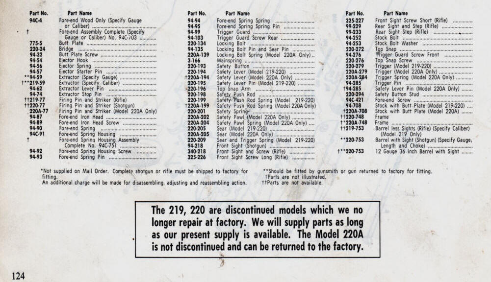
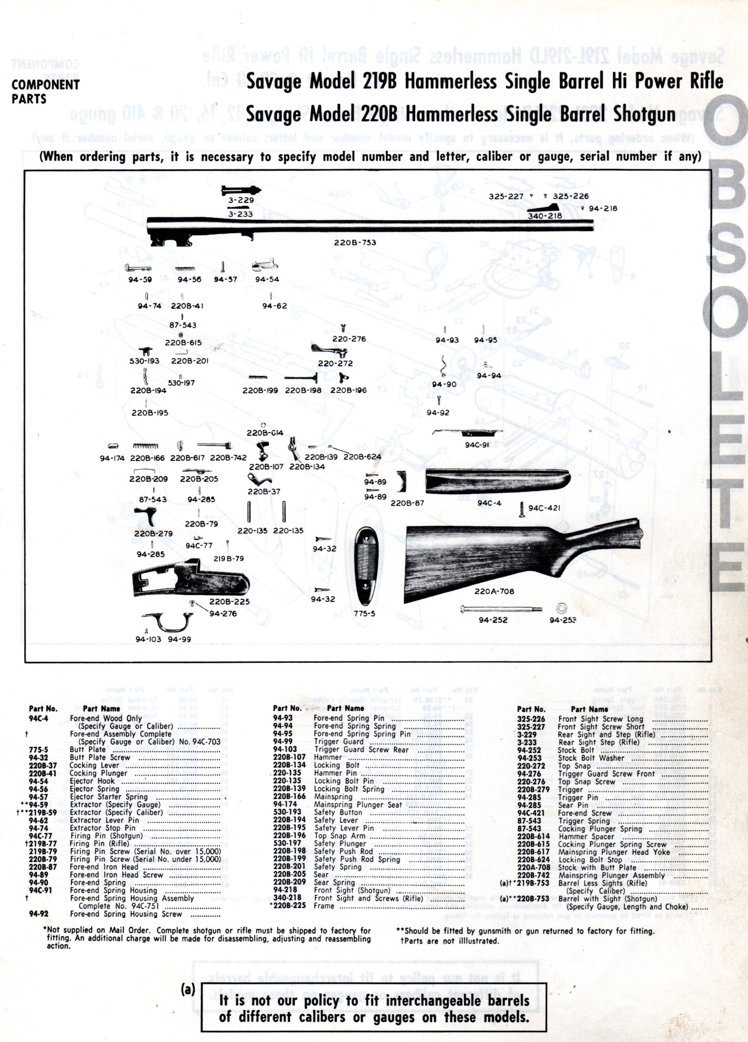
| Here is an exploded view from a 1985 Savage parts catalog that are reproductions of a previous catalog |
 |
NOTE --- THESE EXPLODED VIEWS, AND PARTS LIST IS FOR INFORMATION ONLY.
AS THE AUTHOR
DOES NOT HAVE ANY PARTS

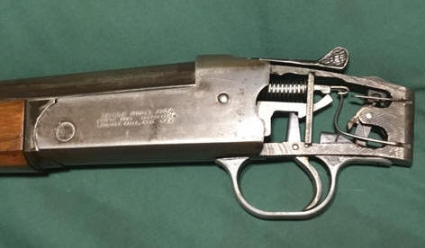
Then photos below were supplied by a reader of this article. You will notice the main differences in the first three are in the trigger, sear, striker/hammer. The fourth "L" series is totally different animal.
| Here the 219 on top with the 220A on the bottom |
 |
| Here the 219B ? |
 |
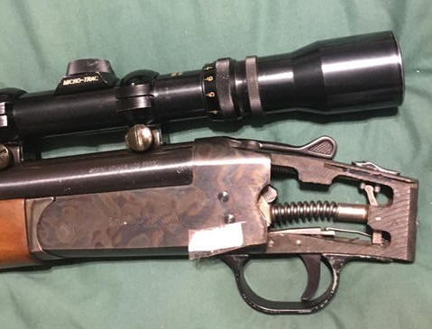
| Here the 219C |
 |
| Here the 220L |
|
|
My History: Being a gunsmith since 1959, I have ran into a few of these hammerless guns. But the first chance to own one was probably in the late 1970s. (1) I acquired a model 219, 30-30 that had been in a BAD house fire. All it was, was badly rusted pieces of metal, the barrel was scaled badly both inside and out, AND badly BENT. All the springs were beyond usage even if I could have re-heat treated them. The trigger guard was an early stamped out sheet metal style and probably the same used on the model 311 double barrel shotguns, and it was salvageable. This gun was totally destroyed as far as all practical purposes.
It has a Utica NY address on the barrel.
At that time I had just purchased a reboring and rifling machine. OK, I hammered on the barrel, knocking off the heavy scale. I then straightened it best I could. I decided to bore it to 35 caliber and chamber it to 35 Winchester. I had to shorten the barrel 3 inches because of the front sight's threaded holes and this large bore that I was going to, but they originally had 26" barrels, so no big deal.
This particular barrel was very soft and easily bent. At that time, I needed re-boring practice, so set it up and rebored/rifled it to 35 caliber but I did not chamber it then. What was left of it then sat in a corner of the shop for probably 25 years. One day I stumbled onto it again, and nearing retirement, "what could I do to make this function again"? My original intent was to make it into a 35 Winchester which had a rimmed case, (fitting the original design of the gun) and at that time I also owned a Winchester model 1895 in that same caliber.
I chambered it to that caliber and tried to get it into something that went BANG. I cleaned up some of the usable fire damaged parts, and re-heat-treated the locking block, firing pin and sear/trigger. But the firing pin spring (mainspring) was of a size and strength that nothing that I could duplicate or fabricate would strike the primer enough force to ignite it. OK, it sat for another 10 years or so. Then my son found a bag of internal parts that fit my gun for sale on the internet and bought them for me. OK, now with the factory mainspring in, I was ready. But in the meantime had sold the Winchester and the ammo that I had, and purchasing new brass for this experiment did not seem logical.
More searching and I found that a 303 British case was close at the rim and rear body as the 35 Winchester, but short in overall length. I had a few old rounds of ammo, AND they went BANG. But fire-forming this 303, the neck came out REAL SHORT. Hey this was a start, now why not try 30-40 Krag brass, which was near the size of the 303, but a tad bit longer. I found almost a full box of old 30-40 ammo in my STUFF. Then somewhere I came across a used buttstock from a Savage model 94 shotgun that fit, which made this little gun into something shootable. No forearm yet however, but the fire damaged forend metal held it onto the barrel. So fire the 30-40 ammo in the gun, fire-forming this case to a shortened 35 Winchester brass. This ammo was old, and I lost about 1/2 of the brass due to splitting in the fire-forming process. The necks are short, only about 3/16" long, but in this single shot, and with lead bullets it has possibilities.
Now with brass on the reloading bench, I used cast 200 grain gas checked lead bullets and loaded them up to the same load as a 35 Remington. I have another box of fired 30-40 brass, but for these, I will anneal the front 1/3rd, to cut down on brass mortality.
I have restored it now, all the parts cleaned, re-heat treated if needed, polished and blued. A new forearm was made and the buttstock sanded down and refinished. An original rear sight and a Williams shorty base front sight and a .312" Marble front sight was added. QD sling swivel studs installed, the front stud soft soldered to the barrel in front of the forearm.
| Here is a photo of my 219 in 35 Winchester after it's reserection |
|
|
(2) Gun number 2 is the same old model 219 but in 22 Hornet, a newer version because it has a aluminum trigger guard. This one just happened to be at a local gun show. I usually go to this show every month, not looking for anything really, but addicted. The guy behind the table who was selling this was a friend of mine. This gun's condition was Very Good, but someone had drilled and tapped it for a side-mount scope and then when it, and the scope had parted ways, someone then drilled and tapped installing Remington 700 sights on the barrel since the scope and mount was not with the gun.
The seller was somewhat of a gunsmith, but his expertise was in pistols and the top lever was loose on this gun, he understood some of the internal mechanics, and since selling it on consignment, did not want to get trapped of going inside to fix that. So I brought it home with me.
Being the ripe young age of 81 and just being diagnosed with Wet Macular Degeneration on my only eye, I wanted to scope it, but NOT a side-mount, as in this situation the scope would NOT be centered over the bore. And also partly because side-mounts are hard to find now days and I did not want to drill any more holes if possible. In my scope mount/sight scrap box I found a side mount base that the 2 outside of the 4 holes matched 2 of the 4 holes already drilled and tapped on the barrel. I also found a single full length top base.
The idea popped into my head to screw the base onto the barrel, mount that in my milling machine and mill both bases to match at an angle, making the top one true flat and centered with the barrel. Then Heliarc weld them together, basically making an adapter type mount using the side-mount holes, but the scope ring base of a top mount. With this machining done, then I had to build a fixture to hold the two parts together while they were welded together. This new mount came out pretty darned good and my alignment was good in that it lays very close to the top of the barrel and with a old 3 power Weaver Classic scope, things are starting to look up. And these tapped mount holes were the larger 8-40 size, holding better than the standard 6-48, so for the time being at least, I just may use it with only the 2 scope base screws, but Loc-Tited in.
So test fire a couple of rounds and, WOW, something is wrong here. NO, but it has been re-chambered to a 22 K Hornet, (an improved straighter case and more bottlenecked.)
But the trigger pull was heavy and the automatic safety system did not function. So tear into it. I found the auto safety parts were missing, but they just happened to be in the baggy of parts that my son had bought for my other gun. OK, I got the firing pin sear notch corrected for a lighter trigger pull.
But the safety button would not slide into the fire position from using the button, however I could get it to go if encouraged it from underneath (with the stock off). What I found was that the front bottom edge of the safety button was sharp and was stopping at the front edge of the slot it rides in. A pass or two with a file corrected that. From this it seemed that the previous GUNSHMIDT could not find this problem, so he just left out the parts that push the safety back onto safe mode on opening the gun.
The loose top lever apparently was because of since this frame was a casting and then machined from there, the thickness of the metal on top at the top lever was thinner on this gun, so I just made a plastic washer out of the top of a butter container, and placing it between the lever and top of the frame, which tightened the lever up nicely.
Now move onto more cosmetics, the ugly sights on a sleek old gun. Both front and rear were drilled and tapped into the barrel (slightly crooked by the way). For the front sight, no big deal as using a standard used factory sight off a Savage model 340 which was what was originally used on this model, and the extra hole is simply covered up.
But for the rear, the original rear sight was the same as shown being used in the photo above, dovetailed into the barrel, The rear sight (when I got it) was attached by drilling and tapping two holes near the dovetail. NOT GOOD. But for these I plugged them with longer 6-48 screws and then cut off the excess. This now was Heliarc welded over, then filed down and and polished, then the whole barrel reblued. When done, a Lyman folding rear sight was installed, which is not original, but vintage and usable even with the scope on or off as it is just high enough to see over the new scope base after milling a shallow radiused groove down the center of the new scope base. This gun now has some eye appeal and considerable better resale value if I ever decide to let it go.
This gun has barrel markings of Chicopee Falls Mass.
Later when I had more time, I sighted it in, but the old Weaver scope was a weak power and had some internal clarity issues. OK, I found another old take off Tasco 2X7 scope, which was better with my deteriorated eyesight.
| Here is a photo of my 219 in 22 K Hornet after it's reconditioning |
|
|
Gunsmithing : If you ever need to do any internal repairs, this is one that, if you are a person who gets exasperated when things do not go as intended, you will have to do many tries before you get it going, or think like the other gunshmidt, things may not go well.
In reassembling these models, it can be very exasperating, as heavy springs need to be compressed and in to confined spaces, along with parts need to go together in a specific order. If it is not captivated, and you try to assemble it in the gun separately, you may be crawling around on the floor looking for parts that went flying. If I was a factory assembler and working piecework, this is one I would rather pass on, unless they has some secret assembly techniques back then.
Reassembly : (1) First off, the front trigger guard screw has to be installed early on as it goes in from the inside before anything else is installed. (NOTE here, if the gun is the very early like my 35 Winchester mentioned above, that screw comes in from the outside). On all the later versions this is held in by a large headed slotted machine screw that needs to go in first (before the top lever unit) as the top lever hole is aligned directly over this screw for easy tightening. IF however you want to complicate things, you can put it in after the top lever and even locking bolt (#134), BUT your screwdriver can go where you can not get a direct purchase onto it because it is inside the frame and rather buried. Many times the threads in the aluminum trigger guard has become stripped and the screw does not go in deeper than maybe 3 threads. These threads are an odd ball maybe a #7 and fine threads, contributing to this situation. And buying a new screw does not fix the problem. What I did was to drill it out and tap to the next size larger, a #8-32. Then I found a round head 8-32 Philips head (stainless steel in this case). My thinking was with the head buried, maybe the Philips head would allow better grip, (but this Philips is impossible to tighten if you do the later installation). I also made the screw a bit longer (.350") under the head, and deepened the hole in the trigger guard, and also tapping it for more threads for a better grip.
(2) Next, you can slide the top snap arm (#196) in from the underneath side with the leg down and on the LH side of the frame, and align the center bar and screw hole with the top lever hole. Place the top lever down into the hole and install the screw, tightening it until it becomes tight.
(3) Slide the locking bolt in from the front with the longer leg to the right. Jockey it around until you get the leg (leverage arm) up and into the round hole on the RH side of the slide the top snap arm. Now you can insert the locking bolt and sear pin (#135) in from the RH side enough to hole the RH part of the locking bolt.
(4) Install the sear and trigger spring (#209) into the round hole in the bottom rear of the locking bolt. It should have just enough resistance to maintain it's position there.
(5) Set the fame and parts you have just assembled aside and now concentrate on the firing pin assembly.
(6) Assemble the firing pin unit (safety push rod #198, firing pin #77, and bridge #24. There is a 1/16" round hole crosswise in the rear of the firing pin. This is so you can compress everything together and then captivate them as shown in the photo below. To do this you can clamp the firing pin front body (while protecting the tip) in a vise, slide the spring over both the firing pin and safety pushy rod (which lays in a shallow grove on top of the firing pin), slide the bridge on using the small square hole, push the bridge down using the long end for leverage. And when the bridge is forward compressing the spring far enough, push a small nail or section of 1/16" welding rod through the hole, captivating the spring and bridge together.
(7) Slide the sear (#205) into position in the bridge as seen in the photo below.
(8) Slide the trigger into the frame, but position it to the rear and out of the way for the time being. (A better time is later (#13) as reassembly is a bear with it interfering).
(9) Slide the firing pin and sear unit into the frame from the RH side. With the aid of a light, locate the firing pin hole in the frame and start the firing pin tip into that hole.
(10) Jiggle this unit, push it forward to where the top and bottom of the bridge aligns with the slots of the frame. Tap the bridge into the frame and flush with the sides of the frame.
(11) Be sure that the locking bolt pin is backed out and only protruding in from the RH side just through the RH side of the locking bolt (you need this room to position the sear in).
(12) Position the rear of the sear so it is now in the cocked position with the firing pin sear notch. This pretty well positions the sear lengthwise. Push/tap the locking block pin into the sear hole, and drive it all the way in.
(13) This time of installing the trigger is better, but you sacrifice a bit of the trigger guard tightness. With the rear trigger guard screw out, rotate it to the left enough to allow the trigger to be inserted into the slot in the bottom of the frame. Slide the trigger into the slot from the bottom of the frame, over the sear and aligning it's pivot pin hole. Push the retainer pin into the frame/trigger.
(14) Position the safety lever (#194) to where it's hole aligns with the hole in the frame, as seen below, install it's pivot pin. NOTE the pivot hole has to be to the rear.
(15) install the safety button (#193) into the frame slot. Insert the safety button stud (#294) into the safety hole from the LH side. Install the safety spring (#201) into the small hole in the upper part of the frame, with the rounded hook end forward and behind the head of the stud. This spring has a slight protrusion on the bottom that rides up and over the stud, retaining it in either SAFE or FIRE position. Be sure the rear tail of the spring is into the slot/hole all the way so it does not prevent the stock from being installed.
(16) Now install the safety push rod spring (#199) rear tail into the slot at the bottom of the frame. Now you will need a needle nose pliers to grip the middle of this spring and force it down while aligning it into the hole on the bottom of the push rod.
(17) Push the top snap, otherwise known as the top lever, all the way to the right compressing the mainspring farther, allowing minimal tension on your retaining pin. Pull your retaining pin out and the action is assembled.
| Here is a laid out relationship view of all of the 219 inner parts |
|
|
In reassembling these guns, the the first secret is captivating the mainspring on the firing pin and the bridge, using a small nail or welding rod in the firing pin assembly hole. The best method to accomplish this is to clamp the front of the firing pin body in a drill press vise (being careful not to break the firing pin tip). Place a 1/2" rod in the drill chuck, align the safety push rod and the firing pin started into the top square hole in the bridge. Crank the handle down as you guide the rod. When you get the spring compressed enough to poke the retainer nail through behind the bridge as shown below, captivating it all together. However poke it in from the RH side and any excess left on that side as if it protrudes on the LH side it will hamper installation.
| Here you see the firing pin, safety push rod & compressed mainspring |
|
|
For Your Information, here are the dimensions of the springs. Mainspring -- .425" OD X 1.800" OAL X.061" Dia. Wire, and 8 Coils Per Inch. The Sear and Trigger spring -- .230" OD X .984" OAL X .041" DW & 11 1/2 CPI.
To make a oversize front trigger guard screw, drill and tap the front of the trigger guard to 8-32 but go a bit deeper, (be aware that you can not go much more because if you go too deep), it will come out the bottom side. New screws can be made a bit longer, like .350" under the head.
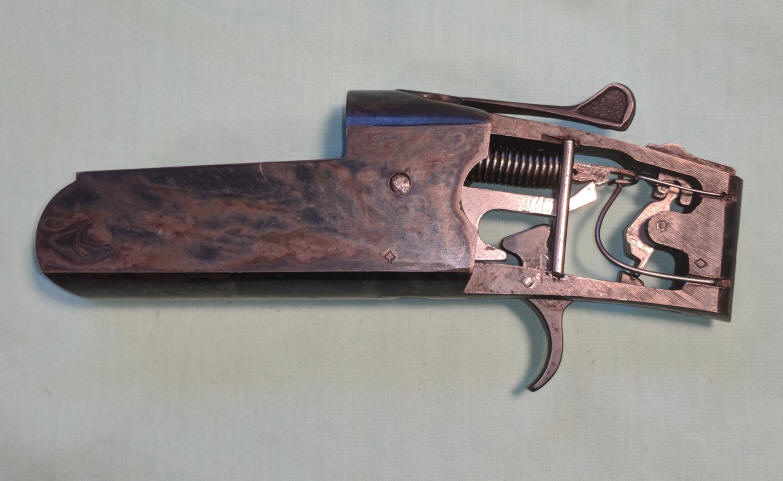
| Here is the model 219 action completely assembled, prior to disassembly as you will note the trigger guard is missing (because of the stripped front screw) also note the case hardened frame color |
 |
Shown in the photo below is a model 219C. Note the second large pin hole on the rear of the frame, the second on is for attachment of a internal pivoting hammer. And the silver colored plunger protruding from the RH side of the barrel lug, which is part of the cocking mechanism, there being a S shaped arm (cocking arm) inside the frame that engages the plunger, cocking the gun when the barrel is lowered for extraction.
The top hole in the frame is a retainer screw for the firing pin, which on this model uses the same independent one used on the model 94 hammer shotguns.
You will notice the narrow stamped out ejector on this model also.
These guns were also factory grooved on top of the barrel for scope mounting as seen in the photo below, showing an old Weaver J4 3/4" scope.
| Here is the model 219C |
 |
NOW-- An interesting addition to
the above article "The Rest of the Story"
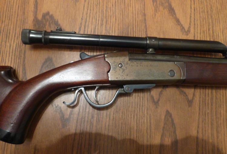
I recently (January 2023) received a e-mail correspondence from a reader named John G, he had a different Savage 219. On the RH side of the receiver was stamped "Built by V S Juenke'. The major difference was it has an underlever, and it was chambered for 219 Zipper. John had done his homework and found an obituary for this gunsmith (which is rather interesting).
The scope and mounts are very reminiscent of early post - WWII, as was the caliber. So in trying to come up with the reason for this re-design. OK, he rechambered it to the more powerful 219 Zipper (a necked down 30-30 case), but the pressure being more than the 22 Hornet, the barrel could have easily become unlocked upon firing. So to cure that he made a underlever which actually cammed a upper lever lug up behind, and under the original top lever activated locking block. He had to leave the original top lever operational as it also functioned to cock the firing pin. In operation, you now have to activate the top lever and then while holding it to the right, move the underlever down and forward.
And in all probability he also may have did a little trigger work. This is limited as the sear spring also functions to operate the locking block, but since he added his new locking lug cam, (securing the locking block), he could lighten that spring slightly. Using this, he could have gained more than what could be done on the original trigger pull.
You can also see that he made a new buttstock for this firearm, raising the comb up for better positioning of the eye to the scope eyepiece. For those of you who were not around in those days, the scopes had very limited eye relief. This scope appears to be an old Weaver, probably only a 4 power.
My guess is that since this gun and modifications pretty well date themselves (and looking at his obituary timeline), it in all probability it was made for himself and not a customer.
Listed HERE is a link is his very interesting Obituary. RIP my friend, you are not forgotten.
| Here the modified model 219 for a stronger varmint caliber |
 |
| I wish this old gun could talk |
 |
Copyright © 2018
/ 2023 LeeRoy Wisner All Rights Reserved
Back to the Main Ramblings
Page
Originated 04-29-2018, Last updated 01-19-2023
Contact the author