| Restoration & Outfitting a 60 Year Old 15' Glasspar Fiberglass Boat That Had Sat for About 30 Years |
|
Money & Time spent on Boat Restoration should be measured in Smiles & Pride
| Restoration & Outfitting a 60 Year Old 15' Glasspar Fiberglass Boat That Had Sat for About 30 Years |
|
Money & Time spent on Boat Restoration should be measured in Smiles & Pride
Here we will be doing some restoration of a 15' 1959 Glasspar fiberglass boat. This boat and motor had not been licensed since 1991. It had belonged to a cousin of mine, but her divorced husband had medical issues later in life, then passed away from Cancer. And this boat sat in a yard unlicensed for 23 years. One of his daughters wound up with it, but her husband had little mechanical ability, was a hunter, not a fisherman, so it sat in a corner of their yard gathering fir, oak, and wild cherry leaves along with cherry pits for another 5 years to the point that it was beginning to look like a garbage container.
| Very Early boat registration numbers |
 |
I had restored numerous old boats (both aluminum and fiberglass) in the past, and one day while talking to her mother, she suggested that I contact them as they wanted it gone from their front yard. This initial contact was made April 16th, 2019.
Thankfully it was sitting on a slight incline with the drain plug pulled. In it was 3 gas tanks, one partly full (that at one time was gasoline) and it had numerous holes at what was probably the upper section of the fuel level. The other two both had bad rust in the bottoms. Both tires were LOW, but still had some air in them. It however had sat there long enough that the grass had died and the tires were sunk into the dirt a couple of inches. The block of firewood that the tongue was sitting on had rotted so much, when we jacked the trailer up enough to replace one tire/wheel, that with just that small amount of movement, the block of wood disintegrated. The trailer was of the vintage that it still used the 1 7/8" ball instead of the now common 2".
Got it Home and Inspect ; On May 13, 2019 after re-contacting her as she had told me that she would get ahold of me when she found the papers. I went to their place and drug it home. Moss and buckets of dead leaves were both inside and out, enough to fill a wheelbarrow. The fiberglass was badly chalked, discoloring it. This boat's design was made more for a runabout/water ski boat than a fishing boat than I wanted, so first off, I pulled the whole rear seat out.
| Water soaked rear seat and rusted gas tanks |
|
|
In removing this seat, it was HEAVY, yes the foam was badly waterlogged. There was indoor/outdoor blue carpet contact cemented to the whole interior. In trying to pressure wash the seats and this carpet, the carpet started to deteriorate because of all the sun's exposure, plus it appeared no way to completely get all the water out of this "shag" carpet, so I pulled all the carpet out.
Now, this left a lot of partly attached contact cement and crudded paint on the inner hull. OK, back to the pressure washer for the whole inside of the hull, which did a pretty good job, with a wire brush finishing the job.
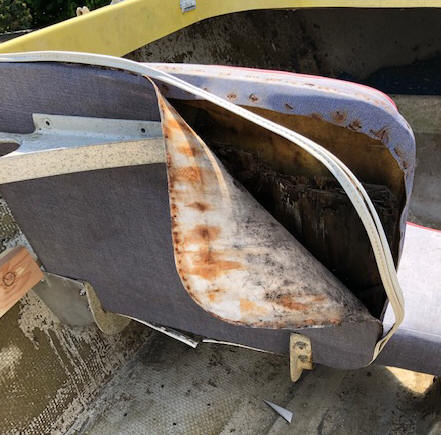
In moving around inside doing the installing of the side shelves, what little hand pressure that was applied on one seat back, it's inner plywood frame disintegrated.
| Time for Duct Tape as a temporary fix |
 |
Again while moving around on the inside, I found one section of the floorboards being spongy, meaning there was rotted wood underneath. Upon further inspection, the fiberglass cloth overlay of the 3/8" plywood floor had numerous holes in it, kind of like something sharp had been dropped (an anchor maybe) and penetrated this thin fiberglass overlayment, allowing water to seep in during the years of it sitting outside uncovered. OK, I figured I could live with that until I got it running and on the water, then decide what to do if I was going to continue this restoration. In cleaning and washing all the remaining loose debris went out the drain plug, I got it dry enough so that after a few days of sunshine, here water showed at some of the larger hole damaged floor areas. This was coming up from underneath the floorboard.
OK just how do I get this water out under this floorboard?? After much thinking, I drilled 3 holes in the rear floorboard, one centered and the other on the outer edges, about 3" in front of the transom, using a 5/8" spade bit used for drilling studs to pull Romex wiring in house remodeling. Next I reversed the Shop Vac hose to blow and covered one of the outer holes, blowing air in. It worked quite well as water came bubbling out of the center and the other outer hole. With the boat sitting on a slight incline and jacking up one wheel, I used gravity to help get as much as possible of this internal water to where it could be blown out. This was repeated numerous times over a few days, to where no more water came out.
Next, I covered these floor damaged holes with auto body Bondo, to temporarily seal it from more water entering, AND plugged the three holes I had drilled with correspondingly sized corks. This should do at least until I get the motor running and see what I want to do with this unit. If the test run proves favorable, maybe a bit of fishing this year and then more restoration during the winter.
Modify the Rear Deck for Fishing ; Having been around and owned a few aluminum fishing boats that have side shelves from the transom up to the front seats, it was my desire to add the same to this fiberglass boat.
The attachment part for both these side shelves/trays was figured out by adding a aluminum 1 1/2" angle against the transom for the rear mount. For the front, another piece of aluminum was fabricated to attach to the seat back attachment on the bottom rear. This aluminum was bolted under the existing seat attachment nuts, and the outer part extended up and out to the side of the hull, forming the front mount for the 1" X 4" shelf bottom, that the outer edge was contoured to fit the hull. This was then bolted to more 1 1/2" aluminum angle, securing it in place. Then screw on another piece of 1" X 4" that was ripped to give a 2" lip, which was then screwed to the bottom of this shelf.
| Shown here are the new unpainted side shelves, & under it, 2/3rds to the rear can be seen the remnants of the old rear seat support |
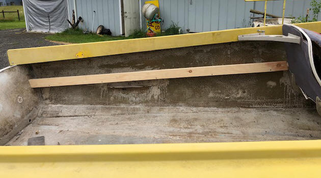 |
I left part of the old rear seat fiberglass support, just in case that I, or some later owner may want to restore it back the the original configuration.
When I drilled the transom to install a second drain plug, I encountered wet plywood. Not rotted but wet, therefor there was the possibility of the transom having some rot under the fiberglass in places. This new rear shelf was in the design to also partly beef the transom up. By adding a 2" X 8" rear self in upper front of the transom, partly for fishing convenience, and to help beef up the possible somewhat deteriorated transom. The real challenge on this was that this transom was not flat, but arced outward in the center, making for a lot of delicate measuring and fitting if it was to help add strength. This 2" X 8" was selected and measurements taken from a baseline, then transferred to the 2" X 8" and bandsawed to the arc shape. Then VERY CAREFUL FITTING was required using a small block plane and hand-held belt sander, fitting to both the transom AND the side's ends matching the rear hull side shape.
Then again another 1" X 4" was added to the front of the 2" X 8" as a lip. All were again secured to the transom by screwing to sections of aluminum 1 1/2" angle up underneath.
With the transom being slightly angled rearward, and
with the 2" X 8" attached at 90- degrees, this tilted the shelf up in front by
3/4". Then to allow for trapped water to escape, a transom drain plug tube
was installed on one side. This now also provides a spare drain plug to
always be at ready if the need arises.
| Shown here are the rear section of the new side and rear shelves |
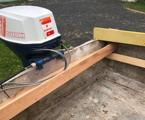 |
Also to make for a more secure motor mounting, a 1/8" X 4" aluminum sheet was mounted under the motor mounting bolt heads, both top and bottom.
Getting the Main Motor Running ; The original Johnson motor had been replaced by a 1981 Suzuki DT65, (65 HP) 2 cylinder, 2 cycle, outboard motor with matching remote controls. And this motor is now considered obsolete as it was replaced by a 3 cylinder 65 HP motor in 1985, so some replacement parts are getting scarce.
There are remnants of the old cable/pulley steering system up under the foredeck. Surprisingly the new style push/pull cable steering worked pretty much as new. The shift and throttle also seemed to function as designed. However the ignition key and corresponding electric choke button were slow to respond, apparently being gummed up by hardened grease.
The fuel line coupler is different than my Yamaha or OMC, but for testing, I made up a adapter so I could use a tank off my Johnsons. Upon inspection, the tanks that came with this deal were all badly rusted internally, with only the smaller one possibly being salvageable for my trolling motor. I did had a spare plastic 6 gallon fuel tank to use for the main motor.
I ordered a new water pump impeller and checked the gearbox oil, which was good. I did not tear it apart and replace the water pump impeller until I was sure that I could get the motor running. And when I did, found that the online mail order catalog was wrong, as the new impeller fits a later 8hp and 9.9hp motor instead of a 65hp.
Then buy a new deep cycle battery, but to conserve space at the transom I selected a smaller type 24.
Fuel line connected, and try to start it, but no fire to the spark plugs. I pulled the flywheel and found the ignition coil had a black color on the coil windings, but in a location that was hard to identify without removing it from the timing plate. OK, remove it, but not sure if it was good or not.
I had looked up on the internet and price of a new one was $89. I had to make a trip to a location where the local Suzuki outboard dealer was located (50 miles away). I took this old coil, along with the online part number. When I got there I asked if he could test it, his response was no, but he would look in his obsolete parts section to see if he could find a match. Bingo, he found one the same shape, but one more laminate than mine and the coil winding diameter was slightly smaller. Price was $25 cash, OK worth a try.
I explained the situation to him and asked for any suggestions. His first response was, "is the lanyard kill button stuck, if that was OK, then it then possibly the ignition switch is bad".
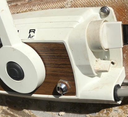
I had early on thought about the ignition switch, but did not see the lanyard kill type that I was used to. There was a small chrome knob protruding on the side of the shift/throttle control, but nothing that I associated to a lanyard kill switch. And I had not climbed into the skipper's station, just leaning over the side trying to get things going. After removal of the shift/throttle controls from the inside of the hull, and a closer looking at this funny chromed knob, YES it was a lanyard kill switch but with the lanyard missing. So in all likelihood there was nothing wrong with the motor to start with. So I swapped out the new coil for the old one, setting aside the new one just in case.
My Redneck repair for the kill switch was to drill a small (1/16") opposing hole on each side, top and bottom, strategically located so that I could then use a soft wire through them to retain the internal plunger being held in, which acted as a semi-permanent lanyard retainer. This deactivated the emergency part, but at least provided a means of getting the motor running until I could track down the proper safety lanyard unit. And I did not ruin the part using this method.
| Shown here is the safety lanyard Redneck over-ride |
 |
Other Electrical Problems ; OK, now we have spark, but the next issue was that apparently internally in the ignition switch, the grease had hardened and in my trying to start it, the key broke off in side the switch. This key movement was hard to twist and what I found was the grease in the rear internal part of the switch contact area had dried out a bit, contributing to the broken key.
Part of my life during my 14 year job as a plant mechanic was locksmithing, so I removed the switch from the remote control unit. My thought was that if I could get it apart, maybe I could drill a small hole in the rear of the tumbler and be able to push the broken key back out. The broken key was twisted enough that it was not possible to push it back out, and could only be removed by removing the tumbler unit could this be accomplished.
I needed a new key anyway and knew my abilities here with my decreasing eyesight, so took it to a locksmith, who only charged me $20 for the repairs which included the new key.
However in all this, the butter container that I had placed the internal parts had got blown over (working on my patio table), loosing some detent balls. I however had some that were close enough to function. I then re-greased the internal parts with a fishing reel grease.
But there was a 5/32" diameter plunger that when you pushed the ignition key when starting, activated a electric solenoid which operated the choke. That plunger had taken flying lessons and was lost in my lawn. I had the diameter of the holes it went in to get that dimension, but it took some trial and error to come up with a replacement of the proper length.
So after much concentration and studying how and why everything needed to function, I got the switch back together and operational. But in trying to start this motor, it soon became obvious that there was carburetion issues.
I also had to replace all of the old electrical wiring for lights, and new wiring to power my sonar, and bilge pump (which were not there previously).
Carburetor Issues ; OK, next was try to start it again, it popped once but was stubborn and gas was leaking badly from the float chamber vent on the bottom carburetor. Time to tear them apart, clean, and soak in carburetor cleaner. First off, I took dimensions of the throttle linkage between the two carbs and the idle screw settings so I would have those to re-set the carbs on re-assembly.
In disassembling the top carb, it looked rather clean, just some debris in the float bowl. However the bottom carb was a total separate matter, having the float needle stuck in the open position, and the main-jet totally gummed up, requiring a delicate cleaning of the numerous small holes in the sides of the main-jet tube. The gaskets came off in really good shape and everything looked good in the reassembly. It was a bit of a chore to get the bottom carb lower retainer bolt in place and tightened because of the confined place.
Final re-assembly was completed and both carbs bolted back in place and the
linkage rod adjustment re-set. Time of truth, but something was wrong, it
would start after much coaxing, but soon die. I finally gave up and took
another good look at the motor. Something was amiss under the RH
side under the timing plate. The linkage arm to the throttle advance was
broken. Not sure that I may have done this when I was working on the
ignition coil or not. Anyway, I removed that arm, took a photo of the
broken part placement and a trip to my local
aluminum welder was in order.
More investigating, revealed the throttle cable was not moving enough,
and I found that there was a bushing missing at the pivot shaft for the throttle
cable connection on the motor. It must have dropped out in my lawn while I
was tearing it apart and before I got the parts in a butter tub. OK, more
rather simple lathe work, as I had the mating parts in front of me, so just make
a bushing to fit the OD / ID and long enough to be held in place when the center
bolt was tightened down.
It Runs - Somewhat ;
After doing the above repairs,
in trying to start it, it would start, idle for a few seconds, but not respond
to the throttle. Upon doing investigating, I found that the linkage
between the timing plate and throttle cable that had been broken had a coil
spring attached to it. Well the return spring had fallen off
and I had missed that on reassembly.
Now,
(and after slight carb adjustments) it runs on the muffs, but not the best, and
I should be able to figure out what needs to be done. OK this is what I was
shooting for, as I did not want to sink a lot of dollars into this project if the
main motor wouldn't run.
I had already spent a lot of time,
but being retired, I have more time than money.
Then, in trying to get it tuned up, it died all at once. No sputtering, just died. I pulled the flywheel and found the Woodruff flywheel key was sheared off vertically. I must have not gotten the flywheel tightened down correctly. Not wanting to make another trip to the marine repair shop, I took as close of dimensions as I could off the old damaged key and lathe turned a mild steel shaft to .750 dia. Then parted it nearly off just oversize from the old key dimension, so I could fit it later. Then mounted it in my vertical milling machine, I actually parted it off where I even had a spare when finally done. The final width came in at .195" and .300" from the flat to the rounded maximum of the half-moon key.
Yes it runs, but seems to have an issue getting up to a higher throttle position, but it appeared to be a timing issue. Since I can not afford to take it to a marine mechanic at $120 an hour, so I have ordered a copy of the factory service manual for $70.
So off into another venture when it comes delving into the wonders of Japanese engineering. This manual being very informative (after re-reading it 14 times) in helping me make initial shifting/throttle/carb adjustments. I even found that this shifting/throttle control unit does have a High Idle provision. That being a nickel sized button at the center of the lever pivot, and by pushing it in, allows the throttle lever to be moved forward (for a higher warm up speed) while being disengaged from the shifting mechanism. Thereby over riding the automatic shift/throttle movement of the single lever control.
Time to Replace Water Pump Impeller on The Main Motor ; OK, now that the motor was actually running, it was time to pull the lower unit and replace the water pump impeller.
Now getting the lower unit off was another thing. Without a manual,
I was grasping at straws as with the 6 bolts out at the juncture of the lower
unit and the exhaust housing, it would not move down more than about 1/4".
The shifting rod was holding it up. OK, go to Google search and found
numerous videos for the newer version motor, but only one a video of a 1984 50hp that
had a rubber snap-in boot covering a slot to access the shifting linkage.
This motor did not have this option, BUT in about the same location, tucked inside the
lower cowling and under the powerhead was a double nut threaded onto a a shaft that was
connected to the shifting cable connection, same as my 1981, but no access hole. This is
a very unconventional
connection,
as you loosen the nut, then push it's shaft inward, and that pushes a connecting
yoke/ J hook that as a plunger that engages a hole in the shifting rods upper
end. On reassembly using needle nose pliers, pull the threaded rod back
out and into the shifting rod hole, then retighten the nut. The
problem is it is located under the powerhead and barely visible.
The shifting rod moves up and down on this model.
OH, BY THE WAY, when using the factory instruction manual, did I mention that you have to disconnect the throttle cable end off the rear control end to really access this nut, OR to have LONG skinny fingers.
There had to be a better way. The later motors have an access hole through the lower cowling to access this shaft/nut. One has a screw on plate, the other just a snap in rubber plug. OK, I located the center of the shaft by eyeball, and drilled a 1/4" hole in the cowling. It was off from being centered of the inner shaft about the size of the drilled hole, drill another hole and a third in a triangle. Now I took a used 3/8" roughing end mill off my milling machine and using a battery 18 volt drill motor, I rounded it to about 7/8". This now gives me access to the end of the shaft and the nut on the Starboard side.
To reach under the
front of the powerhead and access the Port side of this linkage, I heated and
flattened a 5/16" rod on one end, then again heated and bent in a medium short
bend on the same end. This gives me ability to reach under the powerhead,
and leverage to raise or lower the Port end of this shifting rod linkage trying
to align this linkage with the hole in the shifting rod from the lower unit,
when being pulled in from the Starboard. I also did a downward bend on the
outer part to better fit the hand during this manipulation.
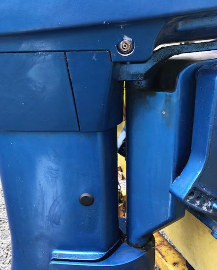
Shown in the photo below in the upper section is my shifting rod
access hole, (not covered by a plug at this time).
| Shown here is the new access hole in the lower side cowling to enhance access to the sifting rod linkage & farther down another access hole (plugged) to facilitate aligning the water tube as explained below |
 |
I also made a double ended open end 12 mm wrench out of .100" aluminum plate. On one end of this wrench, it is the same 10+ - angle as most wrenches, but the other end, probably a 80 degree angle. This wrench will not be used to tighten the nut, but to start or loosen it to where the shaft can be moved out to disconnect or in to connect the shifter shaft/coupler. To do the initial loosening or final tightening a deep socket through my new access hole works best. This hole was opened up to 7/8" and covered with a rubber snap in plug.
Now
THIS IS IMPORTANT.
The shifting rod going into the lower unit operates in a vertical movement for
Forward, neutral, and reverse. With reverse being all the way UP.
But it (this rod) can be rotated 180 degrees, but WILL NOT be FUNCTIONAL. The lower end of the
shaft is connected to a sleeve that has 3 depressions on the rear of it which
engage the spring loaded internal shaft inside the prop shaft, which operate the
shift selector clutch slider. If you unknowingly rotate this shifting rod,
you will
move the gear depression notches to the front, thereby locking the gearbox in
reverse. Therefore it is best to pull/push this shaft before you insert it
up into the exhaust housing. Locate neutral by being able to rotate the
prop, and rotate the shaft accordingly. Ask me how I know.
It is best to keep it in neutral when you install the lower unit back onto the
exhaust housing, however during the pushing and alignment this rod may be pushed
down into forward, which makes for issues later in trying to connect the linkage
pin into the hole in the top of the rod, whereby you will have to by
manipulating the positioning up under the port side of the underside of the
powerhead shifting rod connector and pin relationship.
And if the shifting rod becomes slightly tweaked or bent rearward, it is a BITCH
trying to pull it forward (under the intake manifold and above the transom clamp
bracket) AND align the linkage pin without some help from
a helper. And here there is a very small area where you can shine a
flashlight AND to see what is going on under the power head. Here, it will be
beneficial to remove the carb breather base, to gain some more sight. You
might also consider loosening the gray wire cable and pull a bit of slack,
raising the cable up nearer the electric starter. There is also a red
plastic tube leading from the lower part of the front block to the upper section
that gets in the way.
Now after replacing the water pump impeller, and
in trying to run it, the overboard water blubber exhaust only exhausted hot air
and some smoke. I shut it down and decided that the water pump outlet tube
up into the upper part of the exhaust housing must not have been aligned with
the needed upper hole. And there is no way to see during assembly, just hope it
goes in right. Maybe when everything is new and the grommets tight on this
tube, it will self-align.
I took the lower unit off and back on maybe 3 times but
still the same result. OK, time to drill another access hole in the
exhaust housing near the location of this upper water tube's termination.
By doing some careful measuring and eyeballing, I drilled a 5/16" hole very near
where the tube entered the upper inner flange. But this hole was so small that was of
no use, so I opened it up to 3/4". BINGO, now I can see inside and
by using my neighbor as a helper who aligns the lower unit, drive and shifting
rod shafts, I can guide this water tube into it's upper location by using a wire hook
as he raised the lower unit into the desired location.
These holes were plugged using rubber/plastic plugs obtained at the
local hardware store.
Make Provisions For The Trolling Motor ; Since this is to be a fishing boat, the need for a small trolling motor seems essential. And I just happen to have a 1984 Johnson 6HP that will do this job just fine, but I had robbed it's fuel tank for another motor.
One problem is that I like my trolling motors on the Starboard side, but this boat's control cables were so stout and in the wrong place that I had to move the kicker to the the Port side. And the previous owner had mounted one there. Then space constraints between it and the main motor steering rod/main motor, and the inner deck edge to the kicker's tiller, things are tight, even to the point of slightly limiting some rotational movement, but I left it there.
Finally after the second sea trials, I reconsidered because of displacement/boat balance with my fishing partner sitting in the passenger's seat. So a second revised shot at the Starboard mounting. With some modifications, it is doable and at the same time I have now gained full motor rotation with no interference between it and the main motor.
The main modifications include repositioning the sonar transducer to the Port side, (with just enough extra coiled up cable to do this) and shifting the fuel tanks from side to side. This for me works best anyway for my limited vision (blind on right eye) forcing me to rotate to the right more giving me a centered view down the center of the boat (eliminating a blind spot on the Starboard side). And it provides more room on that side where I like to net my fish, me being right handed.
Clean Up a Fuel Tank for the Trolling Motor ; One of these tanks that came with the boat was a 4 1/4 gallon, which would be better if used on my 1984 6 HP Johnson (than the common 6 gallon tanks), that I intend to use as a trolling motor. However there was still some resemblance of what at one time there had been gasoline in it. Just enough in the bottom to form a slimy covering, AND it was VERY RUSTY.
I have cleaned rusty tanks up before so this was nothing really new, except I added another thought. Why not also use rust remover (phosphoric acid)? The only problem was that with the oily residue inside this tank, it would not allow the acid to do it's job. So pour the acid out, add water and Dawn dishwashing soap and a lot of shaking took care of that.
In addition to the soapy water, I also added a couple of hand-fulls of abrasive machine shop polishing stones. And every time I came near it, I would shake it in all directions for a few minutes. This went on for about a week. Then I drained everything out and put the rust remover back in along with the stones, but no soap. Again, the shake - rattle - and roll, but this time it only took one afternoon to do the final cleaning.
The internal part of that tank came out so rust free that I was
surprised. The only thing that I had to do then was to replace the
internal pickup tube to the hose fitting that was needed as I had to change the
fitting that entered the tank because the old hose was direct to the tank barb,
(no Quick Disconnect on this old tank).
I have done this same thing before but initially used some gravel rocks, which also did the job.
| Shown here are the ceramic stones used to clean the inside of the rusty fuel tank |
|
|
With the main motor running, maybe I had better start the old reliable trolling motor. Surprise, the primer bulb would not pump up on the 4 1/2 gallon rebuilt fuel tank. Maybe in my redoing this tank's internal tank pickup tube, I let more soft solder get inside, blocking it. So I pulled it out, cut that tube in the middle and ran a drill bit in to both ends, seemed OK, so I brazed the tube back together.
I could attach the coupler to the main motor's tank and it would pump up. Hook that to the trolling motor and it would run for a couple of minutes and then suck the primer bulb flat. There had to be a inline check valve failing, so I exchanged the primer bulb for a new one. Still the same results.
I then hooked the main motor's fuel line to the trolling motor tank and the main motor ran fine.
This trolling motor fuel line was all new, that I had made up from new parts and a shorter new hose because of the location, as I did not need the long hose of a new expensive assembled line. The male coupler in it's restored fuel tank was the same aftermarket fitting as the main motor's tank that worked great for either motor. What was wrong??
Finally grasping for straws, I exchanged the trolling motor's female fuel line couplers from one of the hose end to the other tank end. BINGO it worked. All I can think of is that the combination of the new OMC female line couplers and the new SeaChoice male 2 prong tank coupler were slightly incompatible. These male couplers have a small needle like protruding pin that is in reality a check valve when disconnected, so that fuel will not leak out. This needs to be depressed when the female coupler is connected and locked in the slot. For some reason, one or the other on the suction end did not depress that pin far enough to allow fuel to flow from the tank, into the line and the motor.
I knew the fuel pump was working as evidenced by the collapsed primer bulb when it did run.
Trailer Inspection ; The trailer had been repainted, covering the manufacturer's name decal, and the serial number plate was missing, with the rivets holding the plated rusted off. The only way now to even identify the trailer manufacturer was do a lot of internet searching and compare photos, which it appears to be a Tee Nee brand (which was very common in those days).
Next was inspect the trailer wheel bearings. After getting one hub off and looking at the bearing races, there was enough rust to warrant purchasing new wheel bearings for both sides. This trailer apparently is a 1959, (matching the year of the boat) utilizing a 1" axle shaft. The current marine catalogs sell wheel bearing kits identified by the axle shaft (ID of the inner bearing). OK, I ordered two of these bearing kits even before pulling the outer race from the hub. With the first hub apart and cleaned/repainted, I proceeded to press in the inner bearing race into the hub. It went harder than I would have expected, so not wanting it to get crooked, I used the old race as a pusher.
At close to it being in, there was a POP and the inner hub bearing housing split. OK, now cross reference the old outer race to the new outer race, it was a different number, but knowing there could be a cross-reference, did not think too much about it. I even thought maybe the Chinese one was warped until I measured both with a micrometer. The old one (Timken #07196) was .010" smaller (1.970) while the new (Chinese import #L44610)) that was 1.980".
Apparently this OLD hub may have been in existence BEFORE the industry standardized bearings for each size shaft. My fault, as I should have not taken all printed data as the gospel. Well another trip to the marine shop, and trade the one unused bearing kit in on a new replacement hub assembly.
Now what to do on the other hub, and not wanting to buy a second hub assembly, there was not enough smooth surface to chuck it in my lathe and accurately bore out just .010". So after careful measuring/comparing the inner race/tapered bearing, I decided to order two new outer races the same size as the older ones and marry the new inner bearing to the NEW outer smaller OD race. Not ideal, but on this small trailer, AND if I keep it well greased AND keep checking the shaft retainer nut for tightness, maybe over time they will wear in if there is any disparity.
| Shown
here is the broken hub, all painted up & no where to go no where |
 |
OK, after replacing the hubs and bearings in both, I added a set of Bearing Buddy grease retainers.
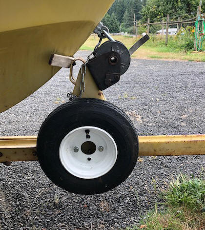
Time now to look at the 4.80" X 8" trailer tires. One, the tubeless (2 ply load rating B) spare would not hold air. The other two were 4 ply load rating C) fitted with tubes and did hold air when pumped up, but the rims were heavily rusted. I pulled them off the rims and cleaned repainted the rims. While doing so, one tire had deep sidewall checks, so it was replaced. Later the other tube became defective so, I just replaced that tire with a mate to the previous new one and also a added a new tube. I do not really like tubeless on these trailers, my reasoning is that I can patch a tube along the road and get things going again if need be, but with a tubeless, that's not really an option.
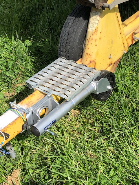
I then mounted the tubeless tire and wheel on the trailer winch support as a spare as shown in the photo on the left. In the right photo, you will see a non adjustable jack stand that had to have a 4" section of 2" tubing welded in to lengthen it to the proper height. And a section of galvanized corrugated cat-walk for a foot stand while recovering the boat was attached by U bolts around the tongue.
| Shown here is the spare tire/wheel mounted on the winch support | Here is the modified jack stand and foot platform on the trailer tongue |
 |
 |
Trailer Wiring ; Now, with things nearing initial completion, I needed to check the trailer lights. You guessed it, lots of rust and corrosion in the lights and Jerry Rigged plug-in connections' on the front. After fighting it for a bit, I gave up and made a trip to Wal-Mart for a new set of automotive trailer lights.
OK, now remove all the old wiring and start over. And it was a good thing, as I found one broken/burned wire inside the trailer frame when the old wire was removed. Here we, (my neighbor) used the old wire to pull new wiring in when ever possible.
Then to make these lights as waterproof as possible, I used 1/16" cork gasket material (obtainable from your automotive parts store) and made gaskets for all the lens covers. But before reattaching them, I caulked the holes the wires came into these units, and for the license plate side, around the clear lens on the bottom.
Trailer Hitch ; In doing the rewiring, the old 1 7/8" hitch was installed INSIDE the main 3" tongue, and it was such a close fit that it needed to be removed to get the new wire ran in. The two 1/2" bolts were rusted in so bad and the nuts were pretty well inaccessible up inside, so time for my Oxy/Acetylene cutting torch. And a new 2" hitch replacement which straddled the 3" steel main tongue was added, making for a easier/better finished product.
With this new hitch, this also called for new safety chains. Then time to repair the old original boat rear tie down clamps.
More Trailer Things ; Well, now that I have two full fuel tanks and a battery mounted at the rear against the transom to give fishing room, I have, by adding that weight at the rear, changed the balance point of the boat on the trailer. It is so near balanced that by just putting my hand on the rear of the boat I can push down lightly and could raise the tongue of the trailer off the ground. This trailer is designed by removing a few bolts that the axle can be slid rearward to change this balance and put more tongue weight onto the hitch. We moved the axle rearward two sets of holes, or 8", and the same for the sway bars, which made a dramatic difference and seems about right now for the size of this boat.
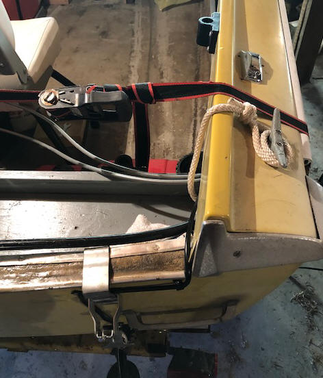
Then, the old style chain and tension spring to a clamp over the rear top of the transom maybe was OK 60 years ago, but most newer small boats now simply use a ratchet strap over the rear top gunnels. I had found a perfectly good single ratchet strap laying in the middle of a street in the local town, which I snatched up. This was modified to fit the boat, (bottom end lengthened so the ratchet handle was on top starboard side instead of on the outside). In this modification, the strap was long enough to be cut and with a trip to my local upholsterer, the now shorter strap ends folded over, sewn into eyes, extending one hook end from 12" to 40".
Other
Essential Things ;
The one thing that I did here, was that about
all bolts/nuts etc. that were used in this project were either stainless steel
or aluminum.
With the main motor running and the trailer wheel bearings replaced, it was time to focus on other things inside the boat. This entailed locating the final locations for the fuel tanks, battery box, bilge pump, rod holder and downrigger locations. The fuel tanks and the battery box were secured by using battery box strap brackets screwed to the floor and 1 1/2" Nylon webbing and quick disconnect buckles.
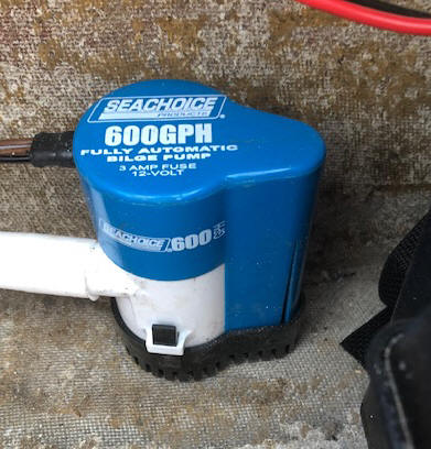
Initially I wanted a automatic float operated bilge pump, and the one that I got sold, the marine mechanic that was the shop salesman that day was more than a tad bit uninformed. He said that many of the newer automatic ones are computer controlled, having the power ON all the time but the motor not running except when it intermittently turns power on and if it senses liquid, it will turn on and pump. I did not like the idea of if the boat was moored for a while, that the battery may be drained down some.
BUT, upon getting it home and reading the wiring diagram, this pump as the option of wiring it either direct OR automatic OR BOTH. Here I wired it into a 2 position OFF-ON-ON switch and now I have the best of two worlds.
| Shown here is the Bilge Pump mounted between the battery & behind the fuel tank |
 |
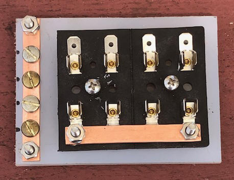
In getting the new boat wiring all in place, I needed a 3 fuse block to connect the Sonar, bilge pump and lights to. They only make a 2 or 4 in this size. OK, 4 works with a spare open holder which can hold a spare fuse. However the marine fuse blocks sell for $32, way more than I was willing to spend on this old boat. So a trip to Car-Quest and ordered a 4 fuse-block for $7.86. This block however did not have terminal bars, and me not having a brass or copper strip laying around to make both the ground and power bar, I simply bought 1 foot of 1/4" copper tubing and hammered it flat, then drilling the appropriate holes.
I also cannibalized (4) #8-32 terminal screws off an old duplex outlet, bought some more #8 screws to mount things up and now have a somewhat equal part for about $10. I mounted it onto a sheet of 1/4" Nylon that I had, but this could also have been a wooden block. The spade connectors make it easier to attach the wires, than by screws when you are laying up under the dash in a very uncomfortable situation. The bottom power bar simply lays on top of the center two spade connectors, but I did smear some dielectric grease on them to provide a better connection.
| Shown here is my CUSTOM Red-Neck made economy fuse block |
 |
Then there was
installing a aluminum backing plate under the new larger mooring cleats at the rear and
moving the old rear ones amidships. Both of these were installed by using
a 1/8" aluminum backing plate underneath the side deck to provide a more secure
usage as when I got it, one cleat had torn a chunk of the fiberglass out side
deck.
I also removed the old telescoping rear white running light, replacing it
with a removable one, as this was to be a fishing boat and I did not want
anything that would interfere above the gunnel with the chance of a salmon landing net getting
caught and tangled, seconds before it would be needed. Then rewiring the
lights needed to be done, and pull more wire from the battery for the fuse block
and on to the Sonar/GPS unit power.
The Sonar/GPS Lowrance HDS-5 unit was a used one off my 18' NorthRiver when I upgraded it to a HDS-7. But I had to replace the transducer unit as the other one had gotten broken. Then it (the unit) proved to have issues of not being able to move easily from one program to another. So I bought another used operational HDS-5 from a friend when he upgraded for $150.
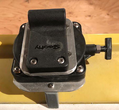
I mounted a used hand cranked Scotty 1085 (30") downrigger that I had as a backup for my NorthRiver boat on the gunnel, but needed to add a 1/8" angle stiffener inside the gunnel even though it was already backed up by 1/2" plywood. Wanting somewhat matched sets of downriggers, I kept pretty constant watch on Craigslist, but it seems that all the sellers wanted local pickup, AND/OR first there with cash. I finally found a model 1080 (24") closer to home (50 miles) and made contact with him. These new sell new for $300 and I got this one for $120.
It is very cumbersome using the standard hinged Scotty base, and I dislike the Scotty swivel units. They (the standard base) however are not very desirable, in that the downrigger is locked in the outward position and can only be that, or straight UP, not good. I initially just bolted the Scotty downrigger base to the aluminum angle.
On my NorthRiver boat, I adapted a Cannon low profile swivel base between
the attachment plate and the Scotty base. I like this over using the
Scotty swivel unit as Cannons are only about 1" high, while Scotty is about 4".
The Scottys may be fine for a larger boat, but not on my smallish fishing boat.
So
one of my winter's projects (and Christmas gift to myself) was to install these Cannon low profile swivel bases on
top of my 1/4" X 4" X 6" aluminum mounting plate
that was bolted onto the inside of the gunnel.
Here, I purchased some 3/8" aluminum plate, cut to 4" X 4 3/4" for
each base, this 4" width was needed to supply a full support for the downrigger. It was rather simple to drill 4 holes to match the Cannon
predrilled and tapped 1/4" X 20 holes (4" X 4" X 4" hole pattern). Then
countersink the top so I could use 1/4" X 1 1/2" Flathead stainless steel screws
(to clear the bottom underside of the Scotty base) . Then position the
Scotty base on this adapter, position it and drill/tap 1/4" X 20 in the adapter
using the Scotty hole configuration. Now using 1/4" X 20 Round Head
stainless steel screws, secure everything together and re-bolt it to the gunnel.
This swivel base has 16 different rotational locations, more than enough to get
the downrigger out of the way when making a run.
In the photo below you will notice a screw head holding in place a
piece of 3/4" wood. On this boat the gunnel was not backed with
heavy wood, and even though I reinforced it on the inside with a 3' 1/8" aluminum angle
plate, in the area when the downrigger was mounted, there was some flexing, so this wooden
block is just a stiffener on top of the gunnel, being held in place by the
single screw.
| Here,
I added a Cannon low profile swivel downrigger base |
 |
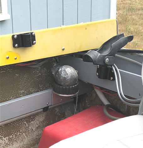
With this small boat, where do I store the downrigger balls when not deployed? My homemade Ball Babies were made from replaced and discarded rubber boat trailer rollers, that have been cut into 2 pieces providing a base in the somewhat hollow center, to keep the balls from rolling around on the floor. But floor space is at a premium here so I made a platform of aluminum angle and screwed these 1/2 rollers to the top of the angle, and bolted the upright angle to my new side shelves very near the transom. Up off the floor and out of the way.
| Shown
here are my downrigger ball bases up off the floor & out of the way |
 |
These
downrigger mounting bolts also provided locations for large P straps to run ALL the wiring
through, including the sonar cable along the Starboard side, between them and
Zip Ties, making a more tidy
looking wiring job.
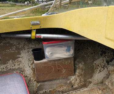
And on the Port side at the front seat area, the factory made a bracket so that the shifting/throttle unit could be mounted on either the RH or LH. So with this unit mounted conventionally on the RH (Starboard) side, I used the LH one to mount another soda cup holder AND a Rubber Maid rectangular plastic sealable container.
Also to store the landing net while under way, it just fits up under
the bow deck, but the handle laying along the Port side, ending just before the
passenger seat back, here to hold the handle in place I attached a battery box
strap loop to the inner side of the gunnel and used a Velcro strap to hold it up
securely, yet readily removable.
| Shown here is my Port waterproof storage container, cup holder and the landing net handle Velcro retianer |
 |
On the RH Starboard side behind the shifting/throttle unit, and on this factory bracket I mounted a cut off pineapple can as a base to set my Freon air horn in.
| Shown here is my RedNeck Freon horn base |
 |
Under the rear of the new Port side shelf, I mounted a boat hook using utility
spring type broom handle clamps, and on the Starboard, very similar setup to
secure the stern light. These clamps were scrounged from other boat
repairs.
The bows for the convertible top were still complete and intact. My lady friend tends to sunburn quite easily so a trip was made to the local upholsterer. WOW prices have went up, $500 for just the top cover, which I can not justify that much on this old boat, so a trip to True Value Hardware and purchase a 6'X 8' 10 Mil premium tarp for $6.49 that I will make my own top from, maybe not as good or fancy, but functional until later when I make and install a taller windshield, which will then require longer bows, which I got used from my neighbor.
Also here I will be using a backup handheld VHF unit that came off my NorthRiver.
Fire Extinguisher ; To pass the Coast Guard requirements all boats need a fire extinguisher, here I used one that was off something else, but was still operational, except the plastic mounting plate strap I found did not match the extinguisher body size, as my canister was slightly larger. So, I modified a 5" farmers scrap aluminum irrigation pipe, for the base and welded it to suit for the bottom of the bracket. And for security, modify it to accept a Velcro strap.
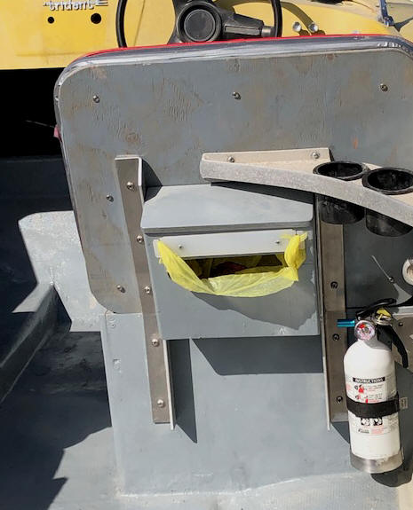
On the rear of the seat backs, I made and installed bird house garbage bag retainers that
installed between the seat back supports and uses old plastic grocery shopping bags as seen in the photo below.
Cup Holders ;
On
this boat, there was a large aluminum brace bracket at the top rear of the front
seats. These had two round holes about 2 1/2" in diameter in them. One more simple but possibly useful item was
to modify these into plastic cup holders. So for accomplishing this, I ground each one
out (using a rotatory air die grinder), large enough (2 7/8') to
accommodate a plastic cup holder. These holders are sold under Seachoice products brand #79481 for $1.55 from many marine dealers. Small fishing boats can use all the catch-all
compartments possible and just a water bottle or soda can holder could be used even for
temporary lure storage.
| Here you see the finished back of the operators seat showing the two black cup holders, bird house garbage container & the fire extinguisher |
 |
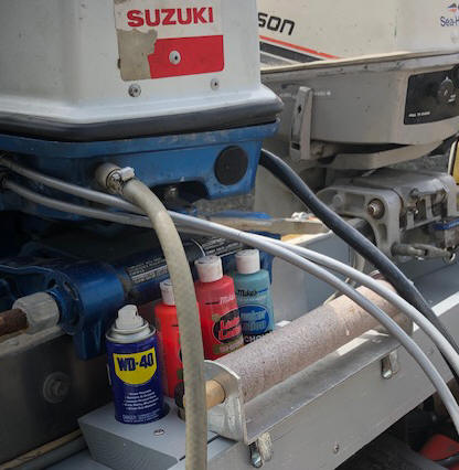
Scent Holder Block ; Then, as a fisherman, I needed a location for my leader spool and scent block, and with limited room, about the only location was on the new shelf directly in front of the main outboard motor. This scent block was made from a 2' X 6" wood block with 1 11/16" holes for most of the scent bottles and 2" for some of the larger and WD40.
| Shown here is my scent holder block & leader spool |
 |
Unintended Consequences ;
OK, with the rear shelf on the transom and the leader spool along with the
scent holder there, when the motor was tipped up to it's ONLY full UP and locked up
position, the fuel line coupler encountered the shelf's lip, and the leader
spool had to be moved. Then the motor also broke off a couple of scent
bottle tops, so they needed to be moved, OR. There was no real reason to tip it up that far for trailering.
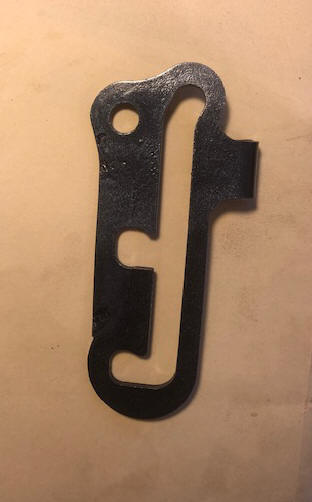
So I removed the tilt locking bracket, welded more material on the edge and
milled out another locking notch farther up, now the motor barely clears the water in this
notch. This now serves two purposes, providing the above mentioned
clearances AND allowing me to raise the motor's lower unit out of the water when
trolling with the 6 hp motor, giving me more steerage by removing the large main
motor's skeg up out of the water. And I still have the full up lock
position if needed.
| Here you see the modified tilt lock bracket. Material had to be welded to the forward edge here to provide strength equaling the original bottom notch |
 |
Rod Holders ; Here I wanted to use the same make/model as on my other boats, (for interchangeability if needed). This make was Tempress Fish-Ons, which I installed 6 based strategically located on the gunnel and rear shelf, with 3 or 4 actual holders.
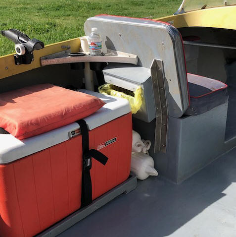
Extra Seat / Storage / Cushion ; Here, I simply used a 48 quart cooler that I had. This acts as a extra seat, and as storage for clothes, lunches, drinking water, even a fish box if needed. The floor here was not level to the sides of the boat, so I had to make a routed out base from a 2X4 and raise one end to have the cooler fit near the side of the hull. Here I also used 1 1/2" Nylon strapping and a QD buckle to hold the cooler down.
On top of this cooler is a boat throwable cushion (USCG requirement), which is held in place by Velcro straps, both front and rear. A note here, it is best to have about 25' of Polypropylene 3/16" rope (this rope also floats) attached to this cushion, and on the other end of this rope I attached a small foam float.
As seen in the photo below, there is just enough room between the cooler and the rear of the seat box to store two boat fenders.
With this smallish boat, where do you keep the salmon net in a readily usable location, yet out of the way? About the only place I could think of was mount it upright directly behind the passenger's seat. So here I added a plastic rod holder/net, attaching it to the inner gunnel and the new shelf below. (the white tube visible behind the water bottle).
| Here is the finished simple side boat cooler seat & storage along with showing the rod holder, new cup holders, bird house garbage & storage for the boat fenders |
 |
Skippers Fishing Seat ; Here I followed my proven design of using a 4 legged metal base, swivel seat and I welded a sheet metal angle on the insde of the legs, up about 4", then added a multi perforated aluminum screen bottom to this shelf so water does not get trapped. I can now carry a 5 quart paint bucket on it, along with a plastic tray as a small catch all for the day.
In the bucket I fill it about 1/2 full of water and add a squirt of a mild soap (Lemon Joy) and use it to throw my flashers, spoons or whatever gear I have when it may be changed out. This makes a great lure catch all, removes any salt water and I have all my gear in the same location to finish cleaning and put away at the end of the day.
| Shown here is my proven design fishing skippers swivel seat |
 |
Better Tie Down Strap ; The original tie downs for this boat were a hook type snap over clamp connected to a spring and chain. This were a PAIN to use, so I modified a ratchet strap that I found laying in the middle of the road in my local town. The modification was to eliminate the short strap on one end and there was enough strap on the other end to use it for the now longer short end, placing the ratchet on top, more readily available instead of being on the side and rubbing the side of the boat. I then eliminated the old stern clamp set.
| Shown here is the old transom tie down clamp and the new ratchet strap. |
 |
Now Time Has Come To License It ;
With the above done and it
began to look like I would have a viable fishing boat, I again contacted the previous
owner and needed a bill of sale so I could apply for a lost title, as she could
not find the registration/title that she received from her father's
estate 5 years before. But getting that accomplished is another LOONG story.
This story started April 13 when I finally caught them home on a
Saturday afternoon, as previous phone calls went to Voicemail, but no one
returned my call. then the box was full, then the landline phone was
discontinued.
Yes, she wanted this relic gone and would look for the papers and
contact me when she found them, (she was sure where they were).
A month went by and no call, so I drove over and caught them home, was she still
interested in giving it away? Her husband assured me YES and come and drag
it off at my convenience. And he would remind her to look for the papers.
The next day, my neighbor and I did just that, needed to air up the tires and
clean out her trash.
I wanted to get the
title transferred and knew that it would take a while. Then instead of the
home phone going to Voicemail, it said the box was full. Then a week later
the phone was disconnected. So another week or so, I got ahold of her mother and got her cell
phone number. But the odd hours that she works, I decided to simply text
her. July 5th was the start of nearly weekly texting, as I had visited
the Department Of Licensing and found that since she never transferred it, she
now had to provide her photo ID, her father's death certificate and a bill of
sale, meet me there as she had no clue what make, size or anything about
it.
OK, she responded, but apparently had no idea of what a bill of sale was.
She asked me to make up one and she would sign it. I then created a bill
of sale off what was there for the boat and trailer. She finally
stopped by after work and signed it without even looking at it.
When asked, she said she had the death certificate. OK when you get it, let me know and we can meet at the DOL. Again, no action as to a follow-up, so I texted again, "What is the status"? She apparently did not have the death certificate, but her sister who lives in a different state and about 90 -100 miles away and was coming up for niece's bridal shower. She would bring it then. Well her sister forgot it, but I did not find out for over a week.
I found out
through her mother that the sister had e-mailed the death certificate and will
to her but she could not open them. But the sister was coming
back up the next week-end and would bring it that time.
My crunch time was running short so I texted her asking if that I
WOULD GET
her dads' death certificate would that speed things up? NO RESPONSE.
I tried to do this online, but did not know all the required info as to the
location of his death and the obituary did not mention that.
I waited another day
and decided to call her mother again and get her sister's cell number.
Then I texted the sister with the dilemma, asking if she could e-mail them to
me? I got a response and the needed info in less than 10 minutes.
I then texted her saying that I had a copy of her dad's death
certificate and when could we meet at the DOL to get this out of our way.
Her returning text, blasted me for my constant texting, pushing her over the edge
and that I overstepped my bounds in acquiring the death certificate. HELL,
if she couldn't or wouldn't, and I had asked her. My text back was I got it
from her sister. That slowed her down a bit, and she agreed to meet me
before noon the next day(after she gets off from work).
. Then at 9PM, I get a cell call from sister #3, saying she just found out about the fiasco and offered to help, meet me at the DOL. I informed her sister #1 was to contact me the next morning, so we agreed to use her as a backup. 9AM the next morning sister #3 texted me and said she would meet me (apparently this sister who had the boat was beginning to feel ashamed and did not want to be in the same room as me.)
The fly in the ointment is she and
her other 2 sisters are listed a co-executors for his estate. DOL
interprets that meaning ALL THREE need to sign off. She lives here here
locally, one sister about 100 miles away, and the other in about 60 miles the
other way. She is the odd-ball and doesn’t really associate with her
sisters. For this, they all have to show up in person, show ID and sign
papers. Which may happen as the sister from the farthest away made
more of an effort and showed up on Friday afternoon on her way up instead of
waiting to do it on her way back home on Monday. Thank You dear.
OK, the local Auditor's office DOL lady got everything under control, making a couple of phone calls to
the main office in Olympia, but then had to wait for a returning call. By
then it was getting late and the office lady was in a bind trying to get all
their backlog cleared out preparing for a upcoming audit on Monday.
So I wrote a check, thanked greatly and took the WSP inspection papers and left.
Thirteen days later (August 29), I got a call from the local DOL
lady, that the main Olympia DOL office had approved the application. It
took me less than 15 minutes to have the papers in my hot little hand. It
appears that the Olympia Office of DOL had achieved records of this boat and
issued me the title without going through a lost title situation. WOW
miracles never cease.
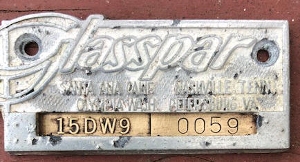
In the end, I did get
to retain the old original Coast Guard number and the boat's serial number.
While waiting, and this DOL lady was on the phone to Olympia main office , she
mentioned we were using the Legacy Program on this restoration. Not sure
what that meant, but it worked as compared to other previous projects that I
had went thru. Now every time I have business in that office, I drop off a
quart baggy of dried pears for her.
Now, since there are no records for
the trailer, AND the original VIN # plate has rusted and fallen off. This
trailer now has to be inspected by WSP, which requires proper papers from DOL
and schedule a date/time set for the inspection. Maybe a week or two the
DOL lady said ???
| Shown here is the original factory ID & VIN number |
 |
Shakedown Cruse ; OK, it is now time to do a an on the water test. We took it to a local lake, (snuck it there using back roads and the old license plate) even tried to drown a worm or two. The main motor needed the idle speed set a bit higher to keep it running when cold, as with no manual, I could not find the High Idle provision on the shift/throttle controls. But otherwise it ran pretty good. However after a couple of hours, my trolling motor's water pump impeller quit. By and large, most everything worked OK, or needed minimal adjustments.
Finally Fishable ;
Well
it has now been a on the water tested and repairs/modifications made, the
trailer inspected and new license plate on it, so we can breathe easier next
time, the date
is now September 30th. Lots of unanticipated delays, and an unexpected
WSP inspection $65 fee, which all should have
been done by the first of August. So I lost basically the most part of my
late summer/early fall salmon season, as I have not put it in the water FOR salmon YET,
however maybe for the
late Coho or even Chum runs that are coming up.
OK, finally got set to do a Chum run, when starting it up the night before, the main
motor fuel system gave me fits. The primer bulb would not pump up. I
changed fuel tanks, that helped enough to get the motor running, but only just
enough to burn all the fuel in the carb. We missed that outing, and I finally
found that the female fuel line coupler at the tank was defective, allowing air
to be sucked into the bulb/line. Maybe it's time to consider adding one of
these couplers to this and my other boat's tool box as an emergency backup.
However part of another delay in getting this boat on the water was
because of the late summer weather, (LOTS OF WIND AND RAIN), and the intended
local lake draw
down to repair the boat launch.
Then WDFW closed about all the fishable waters to Chum and Coho salmon because
their predicted run size never materialized. It seemed that WDFW's
numbers were paper fish, just to get the fisherpersons to buy licenses.
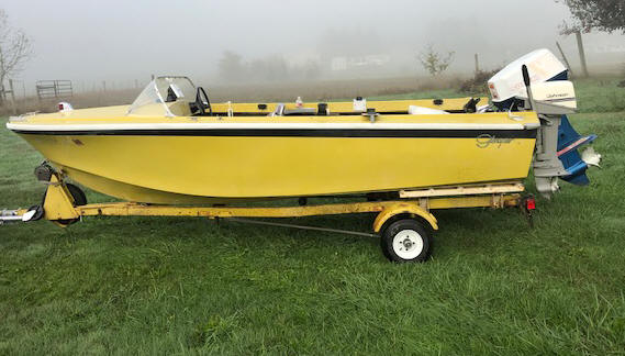
| Here is the somewhat finished product |
 |
There are lots of things to do in the winter, but it is now fishable.
Yesterday, I finally go up enough nerve to cut the bench seat in two and removed
the center section, making two individual front seats with a plywood inner
support, (the Captains, and the passengers)
as seen in the photos below. With the original front bench seat, it was hard to
step over this seat and while the backrests were deteriorated while the boat was in the water (especially for a couple of
senior citizens).
BEFORE
| Here is the somewhat finished product, see the Duct tape on the back of the passenger seats |
Here is the bench seat cut in two & propped up from underneath with a piece of plywood |
|
|
|
AFTER
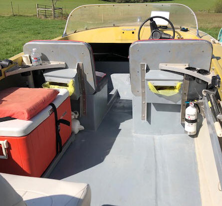
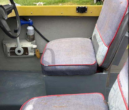
| Here is the FINAL finished product with new floor and seat rebuild | Here is the
FINAL finished hinged seats, NOTE the seat bottoms are swapped right for
left & the backs are placed upside down |
 |
 |
Things to do During the Winter ; Right now, it is fishable, and even being somewhat frugal, my total expenses adding up.
But I have a list of TO DO things after the salmon fishing season is over and between some trout lake fishing next spring.
Those being to cut out the old rotten fiberglass covered 3/8" plywood floor and replace that, along with outdoor carpet.
Then, replace the front seats (both bottoms and backs), with individual raised ones that will have a plywood box support under them which will also provide needed storage.
I also want to install a Tachometer for the main motor but am having a hard time finding a small 2" marine tach.
There are also plans of making the convertible top by partly copying what is left of the old rotted one, but make it taller and using the aluminum bows off a neighbor's 17' Arima. And I picked up enough canvas from a garage sale for the material.
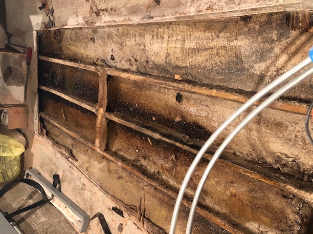
OK, Start of Winter Projects ; Right after Christmas, we had a lull in the normal rainy weather, not too cold and/or rainy, so I grabbed the opportunity and started to tear the floorboards out. These were 3/8" plywood covered with one ply of fiberglass cloth. It covered about 3/4 of the whole floor, leaving a bit of the slightly tapered outer bottom near the edges of the bottom that meets the sides. This flooring edge was prominent enough that I had a guide for the saw cutting.
I set my Skillsaw depth of cut to 3/8", which allowed a smidgen extra, accounting for the fiberglass overlay so that I did not cut deep enough to cut into the hull. With this depth of cut, some places the blade did not even cut through the lower wood layer, which made tearing this floor up a chore, but better than ruining the hull.
This floor was so rotten in places and being fiber glassed to three stringers, which made it hard to remove in one piece to be used as a pattern for the new floor. I did not cut out the whole floor at this time, leaving the front section under the seats for later.
What I found when the floorboards were removed, as seen in the left photo below, was about 2" (probably 12 gallons) of STALE water. The stringers were fiber glassed to the fiberglass bottom, creating needed stiffness to the hull. These stingers seem to be slightly saturated with water (wet) but not rotted.
Upon on getting the water and gunk out of this area, it appears that the stingers were glass cloth covered (but not really waterproofed) but firmly attached to the bottom giving some stiffening. Which is a very good thing.
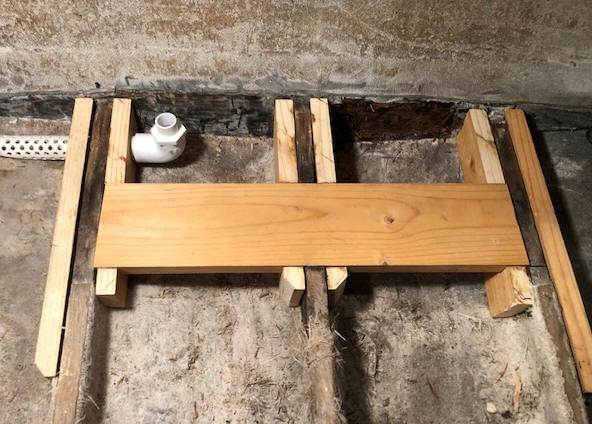
However upon getting deeper into things, just as a precaution, I decided to scab on side reinforcements to the stringers and a wider spacer board, as seen in the photo below on the right. In doing this, I found the transom plywood BELOW the floor WAS rotted. It appears that this rot was only about 3/8" deep as seen by the darkened section on the right where the rotted wood has been removed. Now this transom is arched, so maybe they laminated 3/8" plywood over a arched form and only the inner sheet rotted up to the glue line here.
I dried out the outer parts of the stringers using a heat gun, then used fiberglass resin as a glue to secure the scabs after stainless steel screwing them in place. Then coat the exposed wood with Thompson's Water Seal, allowing it to dry and another couple of coats over a few weeks time. Next was to lay in glass cloth strips and resin from the hull's bottom glass up along the sides of these new reinforcements.
Now that I have things open, I have also decided to devise a method of mounting
the bilge pump in a sump hole to drain the floor better. But after
laying out the locations of the fuel tanks and battery, the pump itself will not
fit in the outer stringer cavity. So this means the pump itself will have
to be mounted inward about 5" on top of the new floorboards. OK, adapt
3/4" PVC pipe to the bottom of the pump (blocking off it's original intake screen) and
running an Ell to a tapered, perforated PVC suction intake into that outer
cavity sump.
Then, to make a cut out in the new floorboards allowing it to be down to the actual hull
bottom creating a shallow tapered sump hole to mount the pump's suction in. This will
allow this bilge pump inlet to be below the floorboards instead of sitting on top of
the floor, allowing the boat to have a drier floor.
To make this well, I cut a filler template of Styrofoam, wrapped it in Saran
wrap and using Bondo built up against this foam the full depth and width of that
Starboard cavity and about 1 1/2" wide. When the Bondo cured, pull the
Styrofoam out along with the saran wrap and there was my dam.
Then using an angle head grinder, I ground off the upper excess Bondo to be level with the stingers and provide a good fit with the new floorboards.
Then by using used just my index finger, but wearing latex gloves, I smeared more Bondo on the inside of this well, filling any voids and making it radiused on the bottom edges, smoother and easier to clean later. This well will then be covered with fiberglass resin as a sealer at the time the new floorboards are being finished.
| Here is what was found (looking forward) under the rotted flooring |
Here are the reinforcement of the rear stringers and the piping for the bilge pump |
 |
 |
One thing for this area, it was designed with no drain plug, probably intended as a sealed air chamber, creating a floatation area. And in those years of boat building before 1977, floatation was not required, but if this was sealed (AIR TIGHT) at the time it was built, so it could have provided considerable floatation.
I have also
decided that filling this cavity with household spray expanding foam insulation,
which will stiffen the boat/floor, add floatation and insulate noise.
Filling these outer shallower cavities with this foam insulation had to be done
on a warm winter day, or cover the boat with a tarp and install a small electric
heater under it for long enough to bring it up to a minimum of 75 degrees.
And then guessing how much was needed before the expansion took place upon
drying was a challenge. Along with it taking more foam than I had
expected, so I decided to just do the outer shallower side cavities. Then
getting the top of this now uneven dried foam cut down to accept the plywood floor,
took more head scratching. I finally found a 5" course open grit sanding
disc for my angle head grinder, that worked just fine.
For the and inner deeper cavities, I used Styrofoam,
salvaged from my ocean fishing ventures or beach walks, which was cut and fitted to these
inner deeper areas.
Floatation being a prime concern along with structural integrity in this
project.
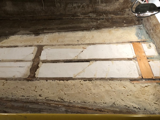
In the photos below, you can see the difference between the sheet
foam in the center and the spray type on the thinner outer sections. I
also added a 4" wood cross reinforcement replacing a 2", which will also help
better support the fuel
tanks and battery.
| Here we see the floatation foam in place & sanded to fit under the plywood floorboard when it is installed |
|
|
In this photo below, you can see where the block foam was cut and fitted in the center sections. This was used from a couple of different sized pieces and some even glued together using the spray in foam. The spray foam, not being captivated, wound up with some air pockets.
| Here we see all the foam in under the floorboad & ready to secure the plywood floorboard |
 |
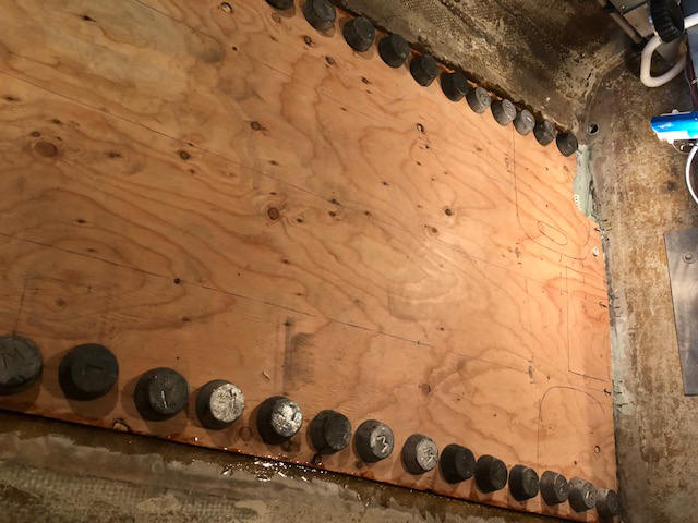
Below, you can see the new 3/8" plywood floor and lead ingots holding down the edges while the resin sets up. This will now be covered with two layers of fiberglass cloth and more resin to make it stiffer and sealed.
|
Here we see the
plywood floorboard installed (fiberglass resin glued) on the edges & screwed to the center stringers underneath |
 |
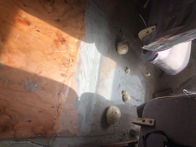
I had not decided exactly how I was going to deal with the front flooring, as the new seats will be attached to it. I hated to go to the hassle that I ran into in the rear section, and this floor looked pretty solid. So I decided to push the rear foam as far forward under the front floor as possible. And drill some 5/8" holes in that floor farther forward, then use more of this spray in foam under that front section, thereby not having to remove/replace the flooring there.
| Here we see part of the plywood flooring covered with fiberglass cloth & resin then the forward spray in foam that oozed out & hardened from the fill in holes, notice the old seats still in place |
 |
With the floor finished with the initial cloth covering, next on
the list was to replace the seats. And with the Corona Virus
outbreak dictating Social Distancing, I had the chance to dedicate some time to
redoing the seats, using the original, but modified cushions. Under them I
wanted to make waterproof storage boxes along with raising them 4". This
raising did two things, made for a more comfortable sitting, along with allowing
me to have room under the hinged seat bottom for a 5 gallon plastic bucket, to
be used as a container for extra storage AND a Porta-Potty when required. This required
a lot of 2AM engineering design, and then converting that to actual
construction, (with design changes/modifications along the way). Do
you know the difference between an amateur and a professional? The
professional can convert a mistake/engineering design failure into a useful and
brilliant improvement.
These seat cushion backs had the interior plywood frame rotted
somewhat and the staples holding the cover loose because of nothing underneath,
to where it had deteriorated considerable at the top inner edge. I made a
extra 3/8" plywood cushion back to help support these existing backs and at the
same time give me something to help secure the back to the aluminum angle braces
that are now secured to the bottom rear of the seat box. I also flopped
these cushions over, putting the bad duct taped top now on the more protected bottom.
These backs were attached by pieces of 3/16" X 1 1/2" aluminum angle which was
also screwed to the bottom rear of the boxes.
Also for the bottom seat cushions, since they were originally a
bench seat, when I cut them and made separate cushions, the now folded over
covering on the inner ends was did not have the sewn in welt, so I flopped them also,
with the RH side now on the LH side of the boat. This way I can (for the
time being at least) have a functional and fairly good looking seat assembly to
get us on the water sooner. Here, the outer part of the box was secured to
the original seat support using 1/4" lag bolts. The inner end of the box
was screwed to a 3/4"X 1 1/2" wood slat that was screwed to the floor. The
front and rear side bottoms were fitted to the floor, attached to the ends and
Bonded on the lower edges, then fiberglass cloth reinforced, also creating
waterproofness.
I also added hinges to these seat cushions, folding forward for easy access to
the storage area underneath.
In the inner front under the dash, was more fiberglass from one side to the other, angled up to the forward shelf under the bow deck. Behind it was an empty chamber, but connected to the under the floor chambers. I purchased a 5" round screw in deck plate from West Marine and installed it there, giving me more sealed floatation along with some dry storage as seen in the photo below. But the fun started when I sprayed more foam insulation in the front section of the floor in front of the seats. Not knowing how much was needed, I had to spray until I saw some evidence that it was filling. A big surprise came when it expanded and cured, forcing foam up into my wanted storage area. That stuff is so gooey as it expands, that even with Latex gloves I did not want to try and take care of it. SO, just wait until it cured an deal with it inside my compartment then.
The one thing for sure is that I now know that the chamber under my floor is completely filled with foam. It took a lot of head scratching to figure out how this now hard foam could be removed by reaching inside the 5" deckplate hole. Finally, I remembered that from my old horse raising days that I still had a hoof knife, which is "J" shaped and when sharpened, I was able to carve most of this now excess foam out.
Also in front of the seats, the floor sloped considerably (about 5") toward the center (shape of the forward hull bottom). This forced a person to sit somewhat twisted toward the center of the boat. What I also did here, was to raise the inner section 3" in line with the new inner seat edge, creating a wedge shaped flat floor for a little over 1/2 of the floor in front of the seats, which also provides better footing when you have to stand up there. These raised floorings were then covered with fiberglass cloth and resin, making for a complete waterproof floor.
|
Here we see
the raised side section floor with old lower floor in front of the seats & the deck plate access, top center |
 |
For the Port-A-Potty, I
used a rectangular plastic 5 gallon Tidy Cat litter bucket which was too
tall, so I cut 1 1/2" off the top (at a flange type protrusion). There are
now two tops, one as a full cover for storage, and the other with a large round hole in the
middle to be used as
originally intended. It could also act as a bleeding bucket if desired. This
rectangular bucket was more space saving than a normal round bucket.
This seat needed a stop to keep it from folding over so far that it
ruined the hinges, so a small brass sash chain and small brass screw eyes were installed as a stop.
The one item that I wanted to install on the passenger's inside cowling was a
grab bar, but with the seats hinged and so close to the boat inner sides, that prohibited anything protruding inward
in that location. The other captains seat when tipped up was stopped by the steering wheel.
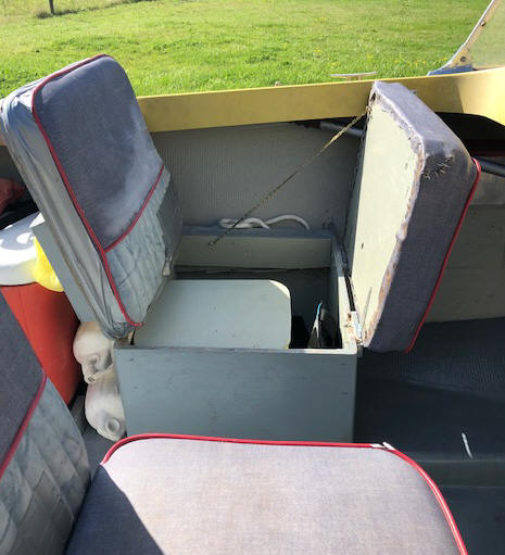
Under these seats I can now store our inflatable PFDs, rain gear, tool boxes, towels in a garbage bag, etc.
| Here we see one of the newer modified seats, the Port-A-Potty bucket under the seat & the raised floor in front |
 |
On the rear of the seat backs I incorporated small "bird house" wood garbage containers (with wide entrance holes), mounted between the aluminum back supports. On the upper part of these, I added easily removable plastic shopping bag holders, allowing the bags to be tucked inside the wood bird houses, making for a more neat uncluttered area.
The spring weather was rather cooler than I had hoped, which prolonged doing the final fiberglass floor covering, so I had to wait for warmer days. All in all, I now have two layers of fiberglass resin impregnated cloth on top of the new plywood floor.
I had initially planned on covering this floor with a outdoor carpet, but had a mind change and simply added a light sand coating into the final machinery gray floor paint that was also used on the seats bases and backs.
The inner sides of the
fiberglass hull was painted a light gray to make a slight contrast.
Also since this boat was made before the current US Coast Guard
requirements came into being, I hand stamped the boat serial number on the right
rear pot metal/aluminum corner casting of the hull, meeting that requirement.
And The Rest of the Story ; OK, everything is ready to fish the summer of 2020. Our fishing club had a planned outing to do some crabbing and bottom fishing at Westport and I was to meet them there, at a 2 hour drive. An hour and 20 minutes into the trip one of the inner tubes in a trailer tire blew an 8" rip in it down the seam. And the old spare was almost flat. I made a phone call to a friend who lived 20 minutes away, who brought me an air tank, but the spare would not take any air (my fault, in my haste, as I did not take off the tube cap and lost all of his tank's air). OK, he drove back to the nearest town and got a new tube put into my tire.
After I got the repaired tire on, the wife asked if we were then too late. No, why? Well she had a dream that night and had gotten a bad feeling. OK, let's, cut it short and go to plan B, stop at a nearby boat launch, but I had not brought any salmon gear.
How about plan C which would be just a boat ride up a close tidewater river? I pulled in there and inspected the ramp, doable there even at a LOW tide. Since it was just going to be a boat ride, maybe I had better pull the 2 crab pots out of the boat and put them inside the SUV. But when trying to move the fishing tackle from the back seat, one rod's line got hung in a fishing bag's zipper. That was it, we were being cautioned by a higher being to not take the boat out that day, so we turned around and went back home.
In my trying to
find out why this tire tube blew I contacted my tire shop and they were adamant
to NEVER put a tube into a tubeless tire as it slips, creating heat. OK, I can see that on a
car tire where the pressure is 32 to 35# and it flexes on each revolution, but
on this small tire 8" where the recommended pressure was 60-90# ?
I then took the boat/trailer to a scales and weighed it.
1480# was the weight (without the crab pots). The recommended tire
carrying capacity for these tires was 1520#. Why had this unit survived for
so many years and now quit on me? The modifications that I had done were
pretty well balanced out by me removing the rear seat, but I added a 6hp
trolling motor and a 4 gallon fuel tank, AND the crab pots apparently pushed it over the
top.
My best shot would to be replace the tires/wheels with 12", but I had to go to the higher load rating of "C" to gain 460# for a new a total of 1980# And I already had a old spare 12" tire/wheel. Since these hubs were 4 holers (and harder to find than the 5 holes), there was no sense in replacing the hubs also. Walmat had tires and wheels, but the tires were the lighter load rating "B". I then found online at Northern Hydraulics the 4 hole tire and wheel at the same price as Wal-Mart and free shipping. I also ordered new plastic 12" fenders.
When the tire/wheels came in GUESS WHAT, the bearings fit the shaft, BUT they were 5 holers. We had a fishing derby planned soon and I was sure that if I contested it and sent the new tires/wheels back, the timing would have put me beyond time to fish the derby and us loosing out AGAIN. Along with the fact that I was now somewhat hesitant to go on the new old smaller 8" tires.
OK, not much
choice now but go online again and order 5" hubs to fit my 1" axles. But
this now gives me no spare, so another expense.
While waiting, I had to devise just how to mount the
new fenders, I mounted my old 4 hole 12" spare tire/wheel to give me needed info for
clearance to
mount the new fenders. I found enough scrap metal to fabricate new mounts that fit
onto the top and side of the trailer frame. But I had given my electric welder to my son, who
had not gotten it wired in and usable yet. So modify the plan, and bolt
everything together, which took a lot longer, and added a bit more weight as my
new brackets are made from a heavier steel than needed, (but it is what I had).
| Here we see the new tire/wheels and fender |
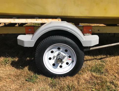 |
However, there are a few benefits to this, the 12"
wheels will not put as much stress on the bearings, and I get a better step for
getting into the boat as these new plastic fenders have step provisions, front,
back and top. I can use my existing Bearing Buddys. And it
raised the back of the boat 3", which was enough to now allow me to back it into
my slightly ramped barn without having to raise the main motor.
And the new wheels have
pin striping.
I should have done this early on at the start of this project, but decided to stay with the 8" ers.
And The Rest of the Story II ; OK, I got it going for our fishing derby, but this boat ramp had a very MINIMAL slope at lower water level section, and I had to get help from other boaters to get the boat aligned on the trailer right (after numerous tries), as it seemed to always want to slip either right or left about 8" on the last few feet when pulling it out. I even had to get in the water way deeper than my calf length boots. Looks like I will now have to devise some rear side loading guides. I have seen other boaters taking forever reloading, and I usually am out in less than 10 minutes, but not this time.
In investigating possible options for these loading guides, the new trailer fender support brackets are going to be ideal to mount them onto. Here I can bolt another angle iron bracket on top of the fender support (using existing holes of that support), then weld a 1 1/4" aluminum pipe onto a flat plate, leaving the bottom open for drainage. Then bolt the plate onto the bolted on angle iron. Then slide a section of 1 1/2 " PVC pipe over the upright pipe. i picked aluminum because I could find a closer fit inside the PVC than if I had to stay with steel.
Initially I did not use both bolt holes in the pipe plates, as I was unsure if the bottom of the sides could be wider part way back. So I just used one bolt, waiting until after I launched/recovered, to insure the boat will slide in between these uprights, as I only have less than 1" side clearance on each side. Then make possible adjustments before drilling the second plate hole.
| Here we see the new guides |
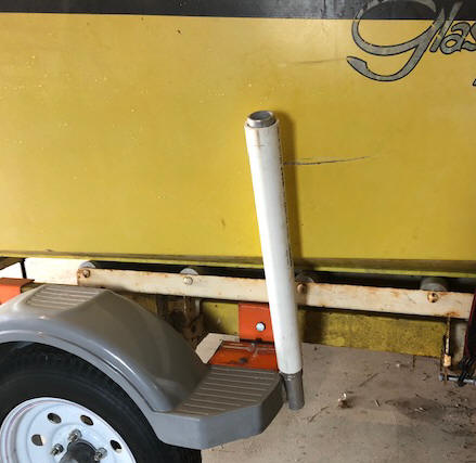 |
And I now have another project, of using these old tires/wheels/hubs to replace what was under a small yard trailer.
All in all, it took 18 months to complete this project (along with a few others along the way). My final total expenses now being right at $2800.00. The boat handles great, takes choppy water with ease, the Suzuki main motor runs great, (except for a funky high idle start system) and I can get 28 MPH out of it at WOT, with it planeing and normal cruising at 22 MPH.
Time For a Change ; I
remarried after my wife of 61 years passed away and we found out that with a
boat launch that did not have a dock, she had a lot of trouble getting aboard
this boat from shore, mainly it had a forward deck. So with a slightly
heavy heart, I put it up for sale as a fishing boat, discounting the total price
I had in it then by just over $1,000. But I have no real interest in it.
It seems that they just looked at the age and figured it was POS, OR if they
were fishermen, they already had their dream boat. Or were just fishermen
who were attracted and stopped to look at any boat that was for sale.
Time to rethink things out. I then pulled all of the fishing
gear, downriggers, rod holders, trolling motor, rear swivel seat, sonar/GPS,
etc. I did replace the sonar with a simple used Garman, and left the
anchor/line, lights, folding seat, but made it into a good basic boat and
lowered the price considerably, where I lost probably about $1,000.
Finally someone who wanted it to crab from, made me an offer and he drove off
with it. And this boat will fit his needs quite well.
Just goes to show, some people do not understand quality, only price, OR they had a Champaign dream on a Beer budget.
copyright © 2019 - 2021 LeeRoy Wisner All Rights
Reserved
Back to the Main Ramblings
Page
Originated 05-17-2019, Last updated 05-28-2021
Contact the author