Maintaining
Johnson / Evinrude
3 & 4 hp Outboards
Made in Belgium 1979 -1991
|
|
Maintaining
Johnson / Evinrude |
One thing that I want to convey here is that I write only on motors that I have actually worked on, and over a period of MANY years, consisting of many THOUSANDS of hours, and then more in maintaining/updating these articles. They are motor specific, HOWEVER if you are having a diagnosis issue, my Trouble Shooting article covers MANY more aspects that may help you diagnose your issue. CLICK HERE for access to that article.
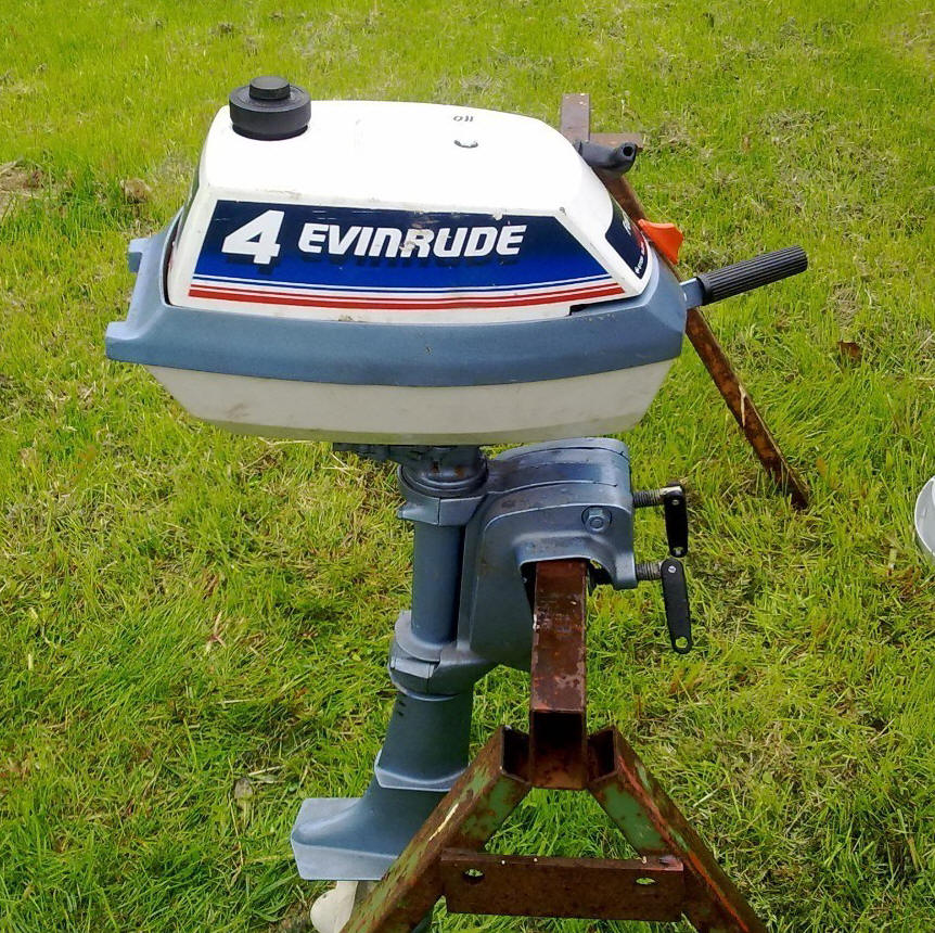
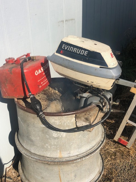
Recently was gifted a 1988 Evinrude E4RCCE 4hp, 2 cylinder made in Belgium that has sat in a pump house for maybe 25 years. This motor was covered with a good coating of dust, It also had at one time been a home for mice (many mice), as they could not have gotten much more debris up inside this cowling of this motor. The good part was this was not a saltwater motor.
This motor also sold under Johnson name made from about 1981 to 1991. Then some changes were made, specifically in the recoil starter and upper cowling until about 2004. These early motors are a totally different design than normal US made motors. But they used US bolts, not Metric. And of course with this small motor no thermostat. This one uses a magneto (points), condensers and under flywheel coils. Some had carb primers on the later motors but this one used a 1986 carb with a choke instead.
There is also a 3hp companion, that pretty much parallels this 4 hp, but is does not have a clutch, being direct drive. It also had a internal fuel tank. This motor apparently uses the same upper plastic cowling as the internal tanked motors as the boss is there for the fuel tank cap location, but just not cut out.
It was not real easy to work on as the recoil
starter is fastened to the upper cowling which is not accessible until you
remove the lower wrap around cowling, but you about have to tip the motor upside
down to be able to see/reach the 4 bolts with a long extension and socket. Here you
DO NOT want to
loosen/remove the single large screw head on top of the cowling, as that is the
single retainer for the starter. Removing it gets you into trouble real
fast. I did not have an issue here as I was initiated a few years ago on a
similar motor.
This motor has a forward and neutral
NO REVERSE gear, but rotatable a full 360 degrees for reverse. The clutch is a spring torsion type used on the
Johnson TN series.
The Belgian engineers must have inbred with the German ones, as the midsection
of this motor is a nightmare. As is trying to change water pump
impellers. There are five 1/4" bolts with a screwdriver slot AND
5/16" hex head holding the powerhead to the midsection. This is no problem, EXCEPT
there is not enough room behind the head of one to get a regular box wrench on and with an open
end wrench only one flat at a time, because of other protrusions near. And
you can't get enough purchase using a screwdriver because they are buried.
These motors are LOUD, probably because there is no insulation anywhere around the motor.
The reason I was interested in this motor, is that it uses the same OMC fuel line coupler as my 15hp that I have on my 14' StarCraft boat. Initially in restoring this 15, I had to row back on one trip before I rebuilt the fuel pump. After that I decided that maybe I should carry a small spare motor (at least until the "revived from the grave 15hp" proves itself). This motor would fit that requirement quite well, as my other small motors use a internal fuel tank and can leak a small amount of fuel if laid wrong. And this one only weighs 5# more than my 2hp Elgin air cooled motor, is a twin cylinder and more thrust because of more HP.
This motor has a decal on the lower cowling near the fuel connector indicating it is recommended for 100-1 fuel ratio at the time it was manufactured. However I will probably be using 50-1 that I use in all my other newer motors, simply because of convenience. After I got it running and the water pump issue figured out, the carb set, I ran it in my test tank at an idle/trolling speed. It made just under 2 hours before it died. Not bad for a salvaged old motor.
It appears to not have been ran a lot, and with132# and 122# compression on initial testing, maybe it will more after it has ran some.
Statistics For These Motors :
These are
Cylinders 2
Bore diameter 1.560"
Stroke 1.370"
Displacement
5.29 CI
Starter
manual independent recoil rope
Gearbox
Neutral / Forward -- 360 degree Reverse
Bearings,
needle rod, main bearing, with
roller top main
bearing
Carburetor - OMC - Tillotson type with choke, throat dia. .750"
High speed jet,
Fixed
Idle jet - Starting point 1 1/4 turns out
Fuel capacity - Remote
tank
Fuel mix - Per gallon of gas,
100-1 as indicated by a decal near the fuel
line coupler
Point gap is .020"
Plug gap .040 " , Champion
L77JC4
Flywheel key - .125 wide
woodruff
Flywheel nut - 7/16" NF, --
11/64"
wrench size
Gearbox Either direct drive, 360 degree steering, OR Neutral/Forward and 360 steering for Reverse
Gearbox oil - 90 wt
Gear
Ratio - 12-25
Prop. dia. & pitch - 3 Blade 7 1/2" X 6" LH
Prop shear
pin - 1/8" X 1.062"
Prop
nut - 1/2" X 20 NC, wrench size 11/16"
Prop Nut cotter pin - 3/32" X 2"
Weight 34.5#
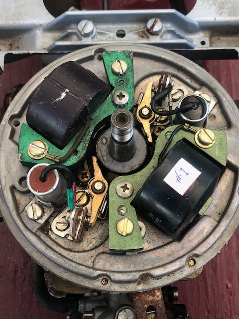
Magneto :
First,
| Here you see the timing plate, note the color difference in the #2 coil & the taller condenser |
 |
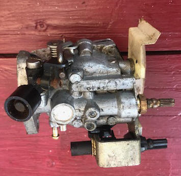
For this model, on the parts list shows a fuel primer, however this one
has a choke. It is obvious that they used parts of the bracket of the
primer to facilitate fitting a choke. In the RH photo, the wire on
the LH side is just a stabilizer to keep the choke from rotating.
One thing here both the choke and idle knobs are identical. In doing
research, it appears this carb is the same as a 1986 model. My guess was
they may have had a parts supply issue and to maintain production, they
improvised, using some older, but in stock parts.
| Here you see the top of the carb | Here, the front also showing the choke. |
 |
 |
Fuel :
Starter :
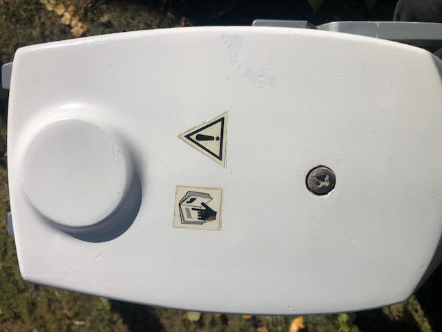
In the LH -photo below you will notice Illustrated decals warning
you to read the manual, (apparently to not remove that starter mounting screw).
This screw IS NOT A TAKE DOWN SCREW, but is the only thing that secures the
starter up underneath this plastic cowling. If you take it out, (or even
loosen it appreciably) you will then be in for a experience reassembling the
starter unit.
Also notice the raised boss on the rear of this upper
cowling, where the internal fuel tank fill spout would have been located.
| Here you see the top of the cowling with the single starter mounting screw | Here, the underside of the cowling showing the starter unit, firmly attached |
 |
 |
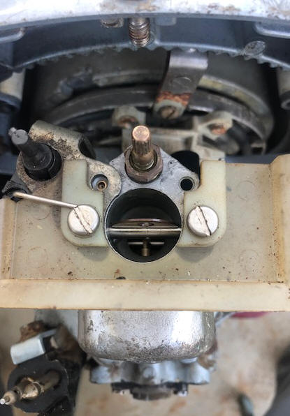
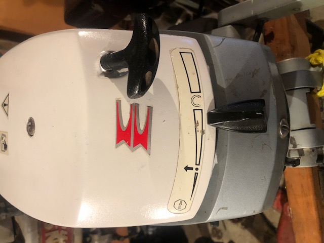
Speed Control :
| Here you see the throttle control lever set at a trolling speed |
 |
Issues :
But it was not peeing, so shut I it
down. Can't find a OWI (Overboard Water Indicator) anywhere, there is a hole on the rear lower part of the
midsection flange that mates to the block, but it appears to just be a drain
hole.
Tried to backflush through water
pump outlet tube (with lower unit off) but cannot get any water to come out of
the motor (appears to be blocked somewhere) OR it is dumping into the exhaust
housing, as I got water there, but was not sure how secure my flush nozzle was.
I tore the power head off to trace water flow. ID'ed the inlet to block
and outlet,
but the outlet is blocked by the base gasket which just pushes water back up
into sideplate area. Back flushed the block, so it is open. CANNOT FIND ANYWHERE
WATER EXITS THE BLOCK. -- FAST FORWARD -- it appears that the overboard outlet
water is diverted into the exhaust chamber. This is accomplished by the base
gasket not totally covering the outlet channel, allowing the outlet water to
escape the block.
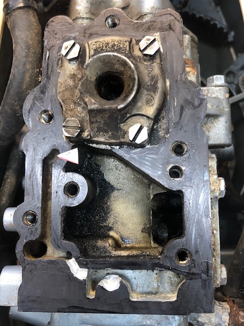
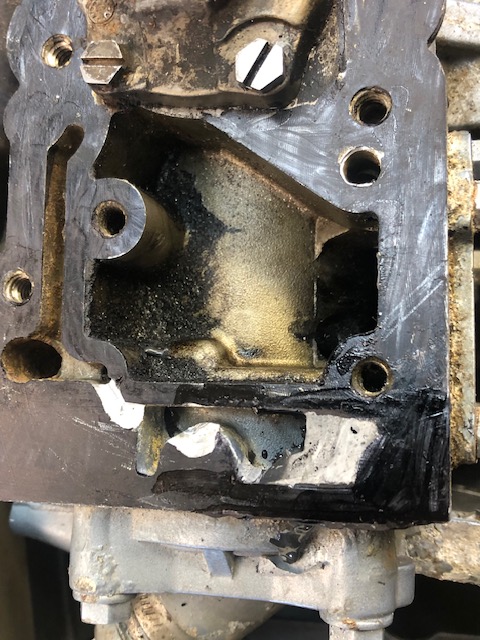
I converted it to an Overboard water Indicator (Pee hole) by grinding a small channel (1/8") in the rear of the block (from the water outlet of the block) to divert water (under a new longer at the rear base gasket) to the small drain hole in midsection rear flange. It appears the gasket opening governs the amount of exhaust water flow, so in making the new base gasket, I reduced this opening by about 1/2 or maybe 3/16", thinking my new pee outlet would then equal about what I had blocked off. With no thermostat and only a 3 vane water pump impeller, they have tried to balance the outflow to the input.
I also had to fill a small section of this new chamber with JB Weld to gain material enough to prevent water blowing out that area. By doing it this way, if my idea is not successful, it can easily be reversed, by simply threading this drain hole and plugging it.
| Here you see some of my modifications | Here, the JB weld added into the cavity |
 |
 |
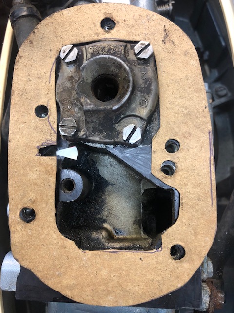
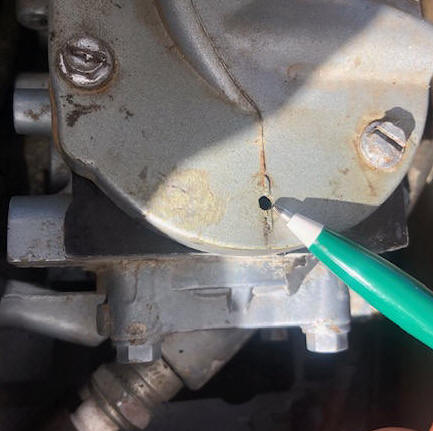
In the LH photo below, you can see the new base gasket with a lesser size for the exhaust water into the exhaust housing. Here the water is guided above this base gasket. The RH photo shows the original drain hole that I have now converted to a Pee hole.
| Here the new oversize gasket (note the white arrow) | Here you see the pointer to the existing drain hole |
 |
 |
Water Pump :
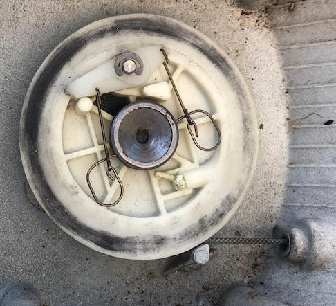
This water pump impeller consist of only 3 vanes, and it being a low volume pump, these vanes do not flex much compared to other water pumps, so if you happened to rotate the prop slightly the wrong direction in your reassembly, the vanes may get flopped backwards. Take my word for it, they will not pump much water in that condition. Here, I recommend that after you get the impeller back in and BEFORE you install the lower unit, to put it in a bucket of water and using a drill motor on the driveshaft give it a try before you button it up to verify that it indeed pumps water.
| Here you see the water pump assembled onto the lower unit | Here you see the water pump impeller from the bottom view |
 |
 |
When replacing the water pump impeller, it is about impossible to get the lower unit aligned with the shifting rod, water tube and driveshaft all at the same time. The big issue is trying to feed the shifting rod into it's blind hole in the gearbox, and the housing was not tapered to the hole for a lead in, just a small hole in a flat section of the housing. And it was about impossible to ascertain if it was in the right location or not when trying to align the water tube.
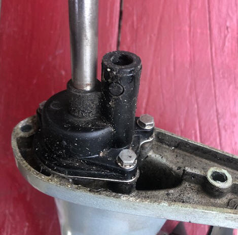
Finally after NUMEROUS tries, I reverted to going totally different method, by pulling the powerhead off the midsection, where I could then assemble the whole midsection/lower unit as a unit and then slide them onto the powerhead crankshaft splines. This was rather unorthodox, in that the shifting rod bell-crank in the upper midsection needs to be unconnected. Here the rod itself is attached to the bell-crank by small cotter pins, but the bell-crank needs to be removed from the shifting lever shaft. There is a small Allen head (3/32") setscrew in the shifting rod shaft, but it is not a setscrew as we know it. It goes into the shifting rod shaft as a retainer (keeping it from sliding sideways), between the two arms of the bell-crank. And behind the bell-crank, between it and the midsection is a small O-ring on the shifting rod shaft. If it gets damaged in your trials and tribulations, there will be a water leak around this shaft when the motor is running.
In the photo below, you can see the set screw. The brass tubing is the
water tube from the water pump, into the block.
One thing to look for when you have this reassembled and
before you mount it to the powerhead, is to look down inside and be sure that
the water tube (being small and soft copper) has not become bent enough to rub on the driveshaft. A
long, large screwdriver is your straightening device here.
| Here is the drive shaft and the shifting rod bell-crank |
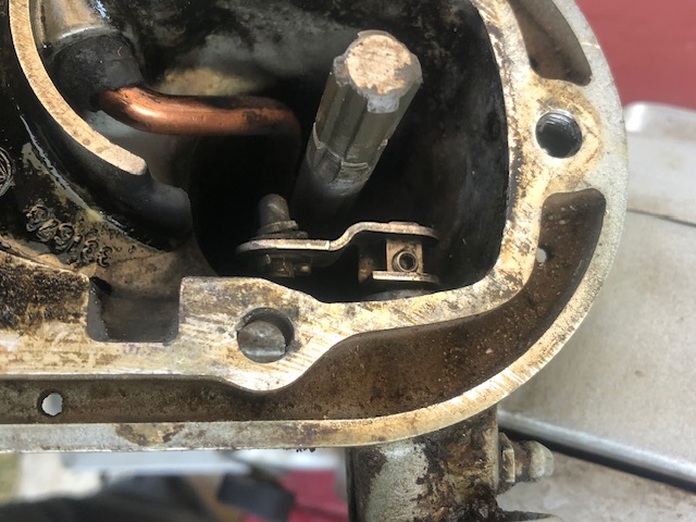 |
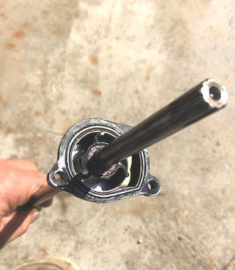
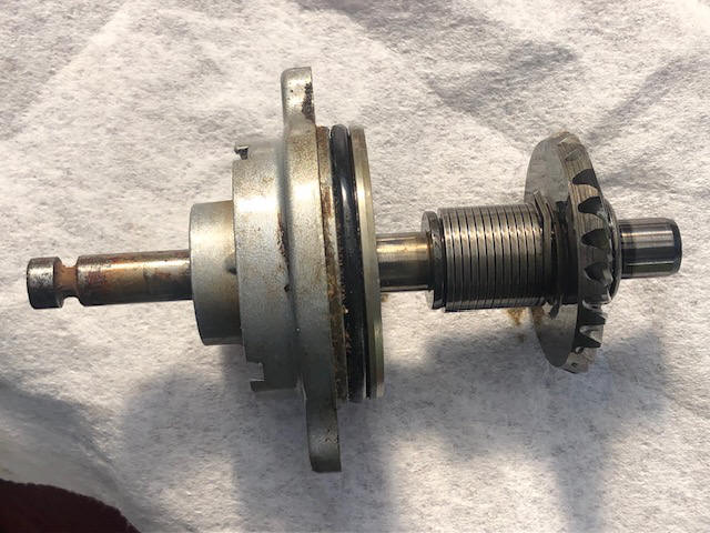
Gearbox
:
| Here is the lower unit | Here is the prop shaft, housing , clutch spring & forward gear. |
 |
 |
If you have pulled the driveshaft out of the gearbox while replacing the impeller, in all probability you will not be able to simply push it back into the drive gear inside the gearbox, as this gear is not captivated, but held in place by the driven gear on the propshaft.
To get it back in place, you will need to disassemble the gearbox. Remove the two 1/4" bolts (3/8" wrench) that hold the rear bearing housing in the gear housing, rotate it slightly so you can get purchase to slide it off rearward. The drive gear, washer and roller thrust bearing will fall out.
To reassemble, slide the driveshaft down to where it just enters the gearbox cavity, slide the washer, bearing and gear in and engage them onto the driveshaft splines. Next you can side the propshaft housing in, but first you need to retract the shafting rod enough to clear the driven propshaft gear. Then push that bearing housing into the gearbox until it bottoms out. Now push the shifting rod down and in place. Bolt the housing back onto the gearbox.
The prop is OMC #0318487 - Plastic 3 blade LH Propeller, 7 1/2" X 6", which is still available at a reasonable price. This prop has a plastic insert in the hub which connects the prop to the standard OMC rubber drive clutch. It is driven by a 1/8" stainless steel drive pin. The prop is retained onto the shaft by a LONG cotter pin that is offset at the rear of the prop. This cotter pin engages a groove in the propshaft.
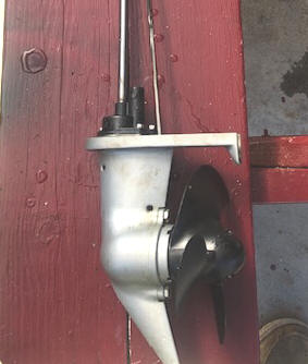
| Here you see this motor in my test tank, running | Here, you see a 1992 3hp, note the different more easily worked on starter system |
 |
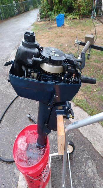 |
| Here you see the top of this motor masked off ready for painting | Here, the repainted upper cowling |
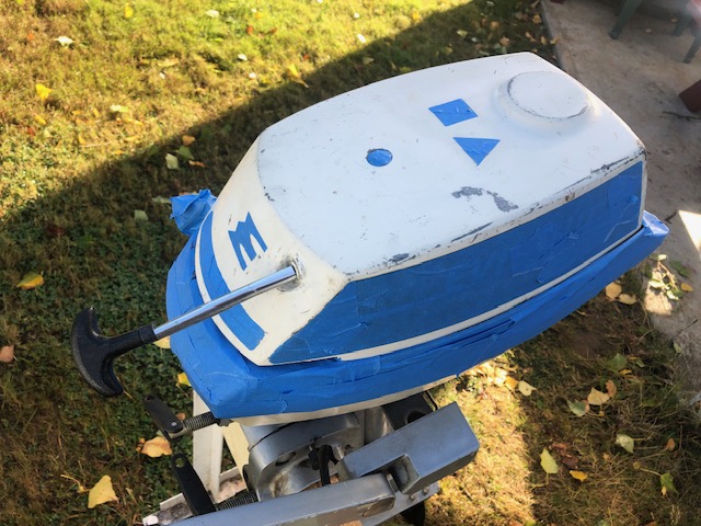 |
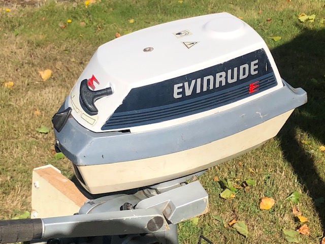 |
Observations :
Back to the Ramblings Home Page
Copyright © 2023 LeeRoy Wisner All Rights Reserved
Originated 09-20-2023, Last updated
10-02-2023
to contact the author click here