 |
Maintaining
Johnson/Evinrude
9.9
&
15 hp Outboards 1993 – 2005 (Converting to Electric Start) |
|
 |
Maintaining
Johnson/Evinrude
9.9
&
15 hp Outboards 1993 – 2005 (Converting to Electric Start) |
|
This conversion is less confusing in finding the right parts as there was only one version of this series of motors
Converting Over to a Electric Start, With Charging System : However this conversion is a lot more complicated as far as parts needed than 74-92 motors and I see no real reason to NOT go the full blown charging system here. Simply because it being a newer motor and the under the flywheel parts needed for the electronics charging will also be more readily available.
These electric start flywheels have the gear teeth machined directly into the flywheel instead of into a steel ring that is used on the aluminum flywheels. You will note by viewing these flywheels that the electric start motor now has NO method of emergency rope starting.
| 1993 - 2007 rope start flywheel | 1993 - 2007 electric start flywheel |
|
|
|
|
|
|
The starter motor mounts are already incorporated into the engine block and the plastic flywheel cover used on both also has provisions for the starter gear clearance.
| 1993 - 2007 rope start electronics under the flywheel | 1993 - 2007 electric start electronics under the flywheel |
|
|
|
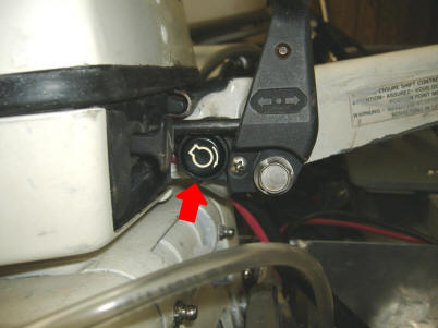
The starter button is buried at the base of the tiller handle at the rear of the shift lever. Stuffing the new wiring harness into the small hole in the handle base and still having enough room for the button unit can be challenging. This starter button incorporates a neutral safety switch with the shift lever, by not allowing proper alignment with the button to enable the switch if the shift lever is not in neutral.
There is no electrical connection between the starter button and the starter switch. The starter switch itself is a simple contact unit with the wires going to a starter solenoid that is tucked in between the fuel pump and the electric starter motor on the port side of the motor.
| Here the starter button is buried behind the shift lever. | Showing the fuel pump on the left, the starter solenoid in the middle & red wires, with starter on the right |
 |
|
There is a Phillips
screw head between the starter button and the shift lever pivot shaft.
This screw allows adjustment to be made to synchronize the starter button to
the neutral position of the shift lever.
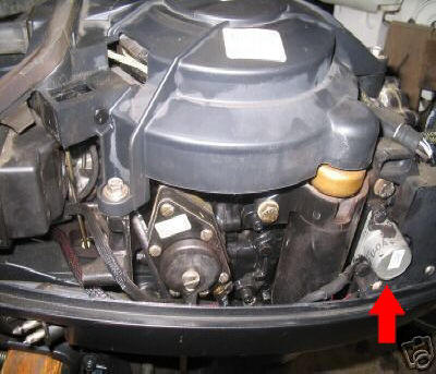
A voltage rectifier is needed on this conversion which is located behind the
starter motor as seem in the photos below. Depending on the year, I have
seen 2 locations of the rectifier.
If you are not changing the under the flywheel electronics and are not going to recharge the battery, you will not need the rectifier.
The red (power) wire goes to the large terminal of the solenoid with the black (ground wire) being grounded to a bolt, usually on the intake manifold.
| Voltage rectifier located behind starter motor from a 96 | Voltage rectifier located behind starter & lower under coils from a 93 |
 |
|
Here I suggest you
try to purchase cannibalized parts off a donor motor, as if you purchased all
the parts new separately, it would possibly not be a worthwhile project.
And in doing so, you will be getting all the parts and wiring including the
electronics so there would not be much more effort to add the electronics
creating a charge the battery system.
Copyright © 2009 - 2020 LeeRoy Wisner All Rights
Reserved
Back to the Main Ramblings
Page
Originated 10-27-09, Last updated
11-29-2020
Contact the author