|
|
Maintaining Johnson/Evinrude 35/40hp Outboards 1965 - 1976 & on, (Information & Observations) |
 |
One thing that I want to convey here is that I write only on motors that I have actually worked on, and over a period of MANY years, consisting of many THOUSANDS of hours, and then more in maintaining/updating these pages. These articles are usually motor specific, HOWEVER if you are having a diagnosis issue, my Trouble Shooting article covers MANY more aspects that may help you diagnose your issue. CLICK HERE for access to that article.
This Family of OMC outboards were pretty popular, ran quite well, had lots of power, however the early models were rather thirsty motors. My experience is that they were rather easy to work on. And when set up right, they were easy to start even using the manual rope starter.
On the early motors, there was no charging coils under the flywheel, but used a separate belt driven generator and a voltage regulator for 12 Volt power.
Carburetors used on the early motors had both a adjustable main and idle jet accessible from the front thru a hinged door.
Lower units on the early motors were the non-thru the prop exhaust type.
| 1971 40hp Johnson fitted with a outboard jet | |
 |
These motors shared many parts and were just larger powerheads than the 15-18hp series as seen below.
The 15's were originally built by Evinrude from '53 on
to '56 and had 19.94 CI. An excellent improvement over the 14's of 1950
and 51.
The FD/Fastwin was even more improved in 1957 as an 18.
For 1957 the FD series was bumped up to 22CI. in the 18HP FD-11. This 22 cube
design was actually the base design for two more models up until 1976.
An 18hp powerhead should mount on
the 15 midsection though and work fine, since this part was the same, from 1956
- 58.
In 1974, the same motor was again modified to produce 25 hp, from the same 22 cubic inches, and sold along side the 18 - 20hp. Carburetion being the main improvement.
The 20hp of 1966 and the 25hp of 1969. One of the
best designs ever built by OMC.
The reliability is good in all the years that they were
built (1957 - 73) but after 1958, when they went to that fiberglass hood set up,
that was the only drawback. Those little rubber shroud mounts usually are broke,
and if you decide to grab the fiberglass lid to beach the motor?
HAH! You only end up with a lid in your hand. The best 18's were
built in '57 and "58 with the good old aluminum clamshell covers. No
plastic parts and they were tough as bullets.
I n the late 1970's the 22 cubic inch motor was dropped, and replaced by a much different design making it a 35hp. The 35hp was detuned to make several versions producing 20, 25, 30hp. But not really the same motor as the old 22 cubic incher.
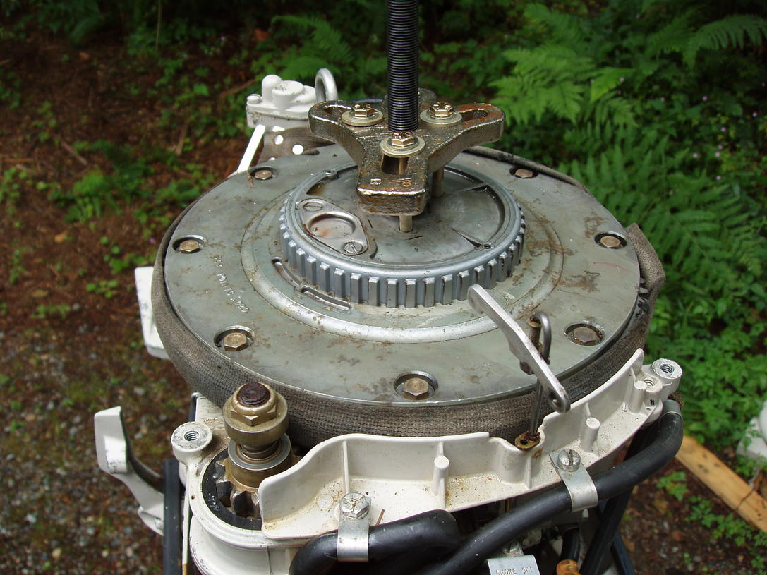
| 35hp Johnson Lark showing the flywheel being pulled with a puller & strap wrench around the starter gear teeth. The upper "gear" is used to drive a cog belt to a generator, if so used. |
 |
In the photo above you can see the smaller center cog gear. This was to drive the generator if that motor was fitted for one. The small plate on the top of the drive gear that is held in by the 2 screws is an inspection plate giving access to the points
Electric Start/Charger ; These early motors could have had a electric starter with charging capabilities. The voltage regulator was usually mounted in a separate box away from the motor. On the motor shown above, it was equipped with a tiller handle and not a lot of room for a tidy installation of a remote type regulator. I took the generator to a farm tractor repair store that also dealt with older "antique" tractors. He took the output information of the generator, cross-referenced to a transistorized regulator that was compatible and yet a lot smaller that could be mounted inside the motor's cowling. Not cheap, but it works. To keep from loosing it's identity, I wrote the info on this regulator.
| 1971 40hp Johnson fitted with a transistorized voltage regulator |
|
|
Electric Starter/Kill Switch ; On these or even the smaller older motors, especially those using remote start, finding replacement ignition switches would probably best be aftermarket ones. There are 2 styles, (1) with a push to choke and (2) the other without. However you might as well buy the one with, and since you may not need the electric choke provision, just not wire in the extra connection. Here you can go to NAPA Auto Parts and ask for marine ignition switch #18-1802 (which replaces OMC's #393301 and #508180).
Lower Unit / Propeller ; On these motors the gearbox is a non thru the prop exhaust, utilizing a overgrown 15/18hp unit. The prop could be one of many, depending on the intended usage, and driven by a 1/4" shear pin. In 1977 the gearbox was changed to the more modern UNITIZED style with the exhaust through the prop.
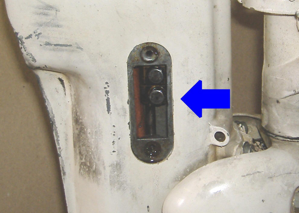
Water Pump Repair : This water pump impeller replace job is a simple remove 4 bolts at the lower unit to mid housing. To access the shifting lever coupler when removing the lower unit, there is a small cover on the right hand side of the exhaust housing retained by a screw top and bottom. Removing this cover, you can then get to the coupler and remove the bottom screw to disengage the upper shifting rod from the lower rod in the lower unit. Now the lower unit should drop down, being loose from the rest of the motor.
In replacing this screw upon reassembly be careful to get the groove that the screw goes into centered in the screw hole before you attempt to insert, tighten down the screw. The one I worked on had a tendency to slide up too far and could bind the screw when it was tightened, stripping the threads. A flashlight and slow movement of the shift lever is needed in this situation.
| Access cover in place on the RH side of the mid-section | Access cover removed, showing shifter rod coupler screws |
|
|
 |
Water pumps are basically the same design as still used on all outboard motors. These impellers are a larger diameter than on some of the later unitized lower units, in my book they appear to be able to still function even after many years of usage even after becoming less flexible. The one thing the early units, was that they were made of a pot-metal
cast housing that after years of neglect, the normal deteriorated condition it will be well worn & or corroded inside (as shown below). It is then recommended to replace the pump unit with the newer nylon housing with a stainless steel liner version if you have plans on keeping this motor in your stable for some time.
| 35hp impeller installed in an older pot metal upper housing before final assembly |
 |
One thing that is a good idea is that the water pump outlet tube's lower end that goes into the water pump grommet is cut at a slight angle. This facilitates this tube being inserted into the grommet so that the grommet does not get folded over, partially blocking the water flow from the water pump.
Any person familiar with normal outboard repairs should be able to replace one of these impellers in 30 minutes easy. The Clymer flat rate manual says it should take 1.3 hours.
| Here the Nylon water pump housing is shown on a gearbox unit |
|
|
It is recommended you replace the water pump to outlet tube grommet as well. This grommet is held in place by 2 "ears" on the sides that snap into matching holes in the top of the water pump outlet tube.
Many times the grommet has been known to not slide over the tube properly, therefore giving a chance to allow the outlet water from the water pump to leak somewhat. So it is beneficial to grease the lower end of the tube to help it slide in better.
| Shown below is the water pump grommet, note the "ears" | Impeller |
|
|
|
|
|
Water Intake : These motors main water supply to the water pump comes from a screened tube right behind the prop in the exhaust outlet. Water is forced into the screened intake to the water pump by the prop thrust. Some users report that when running these motors in a barrel, (usually a small one) that the prop has to be installed and usually in gear as apparently they need to get more water pushed to the water pump by the prop to get enough to cool when running at over an idle.
There is a also a stainless steel intake plate with a few holes near the water pump area on the left side above the cavitation plate shown in the photos below. Flush kits for this motor are rather scarce. There is really no provision currently available for a easy muff system to run this motor out of a tank. But there is hope.
Aftermarket Water Flushing Adapter Cover : These motors main water supply to the water pump comes from a screened tube right behind the prop in the exhaust outlet which utilizes the thrust from the prop to push water up to the water pump. This method of water intake does not allow the newer type of flushing muffs to be used. Flush kits were made for a while for this motor but now are not currently made and are rather scarce. But there is hope.
On the LH (port side) of the exhaust housing just above the anti-cavitation plate there thin stainless steel plate (the factory nomenclature is water bypass cover) which is held in by 2 screws. In this plate are 3 small holes that is designed to put water into the water pump when the motor is in reverse, as shown in the photo on the left below. This is common to many different size of these motors in these years up to about 1974. It was designed to supply water to the water pump when the motor was in reverse.
The right photo is an aftermarket adapter (no longer available) with a 3/8" course thread usually placed in the rearward part. This allows the usage of Mercury's Quick-Silver Flushing Device described below. This flush plate is NOT designed to be used when running, but only for flushing. Since these are no longer made, you can fashion one by using the original plate as a sample and soldering/brazing, (even epoxy) a 3/8" course nut onto the outside of it to screw the flushing adapter into.
The photos below on the left are from a 15hp, but the plate is the same for the 18hp. The right photo is an aftermarket adapter shown on a6hp with a 3/8" course thread usually placed in the rearward part. This allows the usage of Mercury's Quick-Silver Flushing Device described below. This 3/8" hole was not plugged with the possibility of allowing some intake water to be sucked in, or the plug got lost.
| Here is the original cover plate | here is an aftermarket flush plate |
|
|
|
Mercury sells a flushing adapter that uses a 3/8" National Course bolt thread on one end and a female garden hose end on the other. Mercury's Quick-Silver part number is #24789A 1 with the actual name being Flushing Device. Also OMC Johnson/Evinrude uses the same adapter to back-flush their 9.9/15hp 2 stroke outboard motors (and maybe more models) made from 1993 to 2007. These adapters also fit about all of the Japanese outboards that use a back-flush system.
You can remove the 3/8" plug bolt, screw the garden hose into the adapter and then into the motor, then turn on the water. It does not need to be full force of the standard house water pressure, but about 1/2 force. Start the motor up, let it run for long enough to get the motor warm enough to open the thermostat allowing water to flush thru the power-head.
| Mercury Outboard Flush Device #24789A 1 |
|
|
| Prop & nose cone with cotter pin inserted. | Lower unit showing drain & fill plugs and the water intake screen on the leg behind the prop |
|
|
|
Gearbox : If it runs pretty much OK in neutral, but bogs down in any gear, then possibly you have a lower unit / gearbox problem. Unscrew the large headed slotted screw (not the Phillips screw) in the bottom area of the lower unit. What comes out? There should be a dark thick gear oil. If it is a thick creamy color it has water inside. If no oil comes out, your unit has a leaky shaft seal, which may have let water in and then over time also drained out if not ran for some time. If this is the case then you may have a rusty prop shaft or gears. Either of these will put a lot of excess resistance on the motor when shifted into either forward or reverse, causing it to bog down.
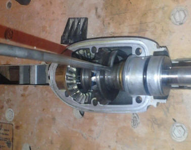
This is not a unitized gearbox like most of the newer motors, and the bottom 1/2 comes off exposing the gears. To remove this lower 1/2 remove the (3) Allen head #2 screws on each side, then the (1) Allen head #1 shifting linkage pivot screw. The lower 1/2 can now be lifted off, possibly may need some persuasion however if someone gooped the 2 parts together.
The lower unit gearbox is not the unitized type as used on the later 9.9s, but has a bottom section that when the unit is turned upside down, exposes all the gears and output shaft. There is a spaghetti type O-Ring that seals the grease in the lower unit when assembled.
This gear case does not use a regular gasket, but a spaghetti rubber seal is .100" dia. allowing the two metals to mate tightly. This seal is purchased in bulk so you cut off just a bit more than you need. For this model 11" is enough. This seal is the same as used on all the other models that have the split gearbox, it may just be a different length depending on the size of the motor. It may do the job alone, but OMC recommended it's 3M 847 sealant, but it's kind of pricey hard to find at regular stores. Lots of folks use Permatex Ultra Black with good success and it's available at almost any auto store for just a few bucks. The main thing is that you want to keep it watertight. Also when you lay out the rubber seal in the groove, cut off just a little longer than needed as it will spread out in groove when housing is pressed together.
When reassembling these gear cases, you should use some gasket sealant on the spaghetti seal itself, both surfaces of the clamshell gear case as well, especially around the bolt holes as well as the perimeter of any oil seals.
In the photo below, this gearbox did not have any nylon washers under the drain or fill plugs, no spaghetti seal at the juncture of the top and bottom halves of the gearbox (just Permatex and a minimal amount at that) and had not seen oil probably for a good number of years, water yes, but no oil by then. About all it is good for now is photography purposes.
| Here is what a boater does not really want to see, so much rust that nothing was salvageable other than the prop | This one
is a lot better, but looking at the gears & bearing in bottom cover with the shifting rod pointing up |
|
|
 |
If your motor will not stay in or slips out of gear, you either are missing the shifter lock detent bar spring on the side of the powerhead, your clutch dog and gears are worn out, or the shift linkage is worn out. Or all three.
Sorry but sold this motor before got all my info
Copyright © 2011 - 2022 LeeRoy Wisner All Rights Reserved
Back to the Main Ramblings
Page
Originally started 4-02-2011, Last updated 01-22-2022