it Running Again
 |
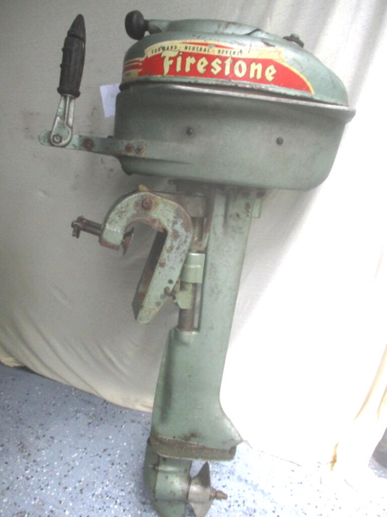
Firestone
1952 5 hp, Getting it Running Again |
One thing that I want
to convey here is that I write only on motors that I have actually worked on, and
over a period of MANY years, consisting of many THOUSANDS of hours, and then
more in maintaining/updating these pages. These articles are usually motor specific,
HOWEVER if you are having a diagnosis issue, my Trouble Shooting article covers
MANY more aspects that may help you diagnose your issue.
CLICK HERE
for access to that article.
What Do We Have Here? ; The motor we will be discussing here was a non running (like possibly for 25 years OR MORE) was a 1952 5 hp Firestone motor that was donated to me by my Son-In-Law that was given to him by a cousin as a result of it not being sold at a garage sale. This motor was made by Scott-Atwater as describe below.
C.E. Scott and H.B.
Atwater owned a small tool making and punch press
operation. They had started the business in 1932. In
1935 a gentlemen named DuMonte approached them to build
a small outboard for him to sell. The motor was put on
display at a New York exhibit. Report has it that
several hundred of the outboards were ordered. Before
the motors were turned over to DuMonte they installed
some decals of the name CHAMPION. They were still doing
their tool and punch press operation as well as building
outboards.
In 1939 DuMonte landed a
contract with Firestone to sell the CHAMPIONS in their
tire stores. This forced both C.E Scott and H.B. Atwater
to start building outboards full time. In 1941 Scott and
Atwater with their CHAMPION outboards were the second
largest outboard manufacturer in America. At that time
only Evinrude was larger. This relationship with DuMonte
and the CHAMPION outboards went from 1935 until 1942.
World War 2 had forced most machine shops to doing
military work and Scott and Atwater were no exception.
After the war, DuMonte decided to build his own motors.
Firestone still wanting outboards stayed with Scott and
Atwater to supply their motors.
In 1946 FIRESTONE and SCOTT-ATWATER outboards hit the market. They offered a 3.6 hp in 1946, adding the 7 1/2hp in 1947. By 1949 their line had grown to a 3.6, 4, 5, and 7 1/2 hp. The 4 thru 7 1/2 outboards were available with full shift F-N-R. Making them the first outboard company with a line of full shift motors.
1950 offered in addition a 16 hp shift motor.
In 1951 they added a 10 hp along with being the first manufacturer to utilize the single line fuel system. This brought their line in 1951 to a 3.6, 4, 5, 7 1/2, 10 and a 16 hp. This same year brought the speed designations on the line of outboards.
The numbers that
have been seen on the cowlings were for a speed rating,
like.
1-12 would be a 3.6 hp. It would push a boat from 1 to
12 mph. This speed designation was only used in
1951 and 1952. You can check the Scott-Atwater
Year
Locator to see all the models and
years as well as the speed designations.
1953 brought on the Golden
Pennant. A dark green bottom and a gold top. This was
only used on the 7 1/2 and the 10 hp. This new
color scheme with the addition of the two outboards
being a thin motor with a band and a cowling that split
down the middle didn't sell as well and was only run
that one year.
In 1954 the invention of
the Bail-A-Matic was introduced on the 5, 7 1/2, 10 and
16 hp motors. This feature would allow you to drop a
small unit in the bottom of a boat and a hose would lead
to the outboard where it would bail out water. In
these early years most boats were wood and as we all
know had the tendency to leak a little water. This
feature didn't win the population over. It had its
share of problems (being they relocated the water pump
and a second pump for the Bail-A-Matic up under the
powerhead which caused cooling problems when things got
worn). The Bail-A-Matic was no longer advertised as a top
feature.
In 1955 they introduced
their 30 hp outboard. In 1956 it was changed to a 33
hp. Their line for 1956 was a 3.6, 5, 7 1/2, 10, 16
manual start, 16 electric start and a 33 hp. This same
year Scott-Atwater was approached by McCulloch to buy
the outboard operation. Scott-Atwater did sell out this
same year. 1956 also saw the last year of the Corsair
outboard. An outboard that Scott-Atwater had produced
since 1946. (I will list the other outboards
Scott-Atwater produced at the bottom of this page.)
In 1957 the 33 hp became
a 40 hp. Although the name Scott-Atwater was still on
the cowling they called themselves Scott. Also in 1957
the fiberglass cowling appeared on some of the
outboards. 1958 saw the beginning of their new 60 hp
that was a 3 cylinder. The name on the outboards
eventually became Scott and Scott-McCulloch. By 1964
all of the motors were changed to McCulloch. Because I
am a Scott-Atwater fan while Cliff Scott and Bruce
Atwater owned them, I only follow the years from 1935 to
1957. All I really know about McCulloch is that
sometime in the mid to late 60's they stopped producing
the outboards. I hope this has allowed you to learn
more about these outboards and the two early pioneers in
the outboard industry.
This list is of the
outboards that Scott-Atwater produced. Some of these
models were picked up by other companies as with the
case with Firestone.
Champion outboards 1935-1942
Scott-Atwater 1946-1959
Firestone Outboards 1946-1957 (may have been into 1958
Corsair Outboards 1948-1957
Hiawatha 1956-1959 (may have been into 1960)
Wizard 1959-? This was only added
because in 1959 and or 1960 the Bail-A-Matic feature was
on some of these outboards that McCulloch produced for
Western Auto.
This page above was copied from http://www.scottatwater.com
Statistics For These
Motors :
Specifications on this
Firestone motor are -- Stock number 10-A-73 Code number
133-2-1725 Serial number1725-4861 which the 25 equals
to Scott-Atwater's year of production and hp code AFTER 1951
being, being (3725 but 1725 for Firestone)
which represents 1952. The 3 (or1) meaning Scott-Atwater, 7 equating to the 5 hp
and the 25 is the year written backwards.
These
are
W
Bore diameter
1.6875"
Stroke
1.6719"
Displacement
7.48 CI
Starter
manual recoil rope type
Bearings,
Ball & Needle roller bearings throughout
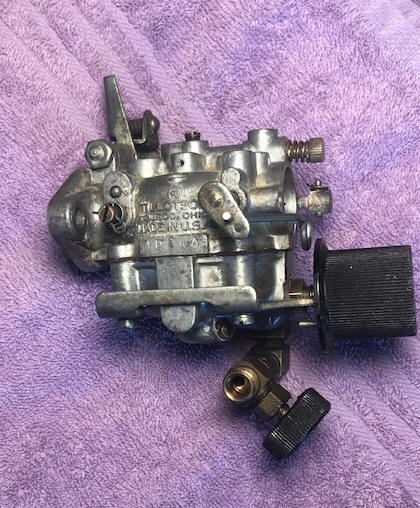
Carburetor - Tillotson MD
High speed jet -
Adjustable
Idle jet
-
Starting point 1 turn out
Fuel capacity -
Integral 1 gallon fuel
tank
Fuel Shut off -
Valve attached directly to front bottom of carb
Fuel mix -
Per gallon of gas, SAE-30 Oil 1/3 pt.
50-1 Ratio
Wico Magneto -
Point gap of .020"
Spark plug -
Champion H10
gap .030"
Flywheel key
-
??
Flywheel nut -
7/16" X 20 NF, -- 5/8" wrench size
Shaft length -
Short -15"
Water Pump -
Rubber impeller
Gearbox - Forward/Neutral/Reverse
Gearbox oil - Hypoid 80 /90
Shear Pin -
None - Slip clutch
Gear Ratio -
??
Prop -
7 1/2"
X 6 1/4" 2 blade RH
Prop nut -
1/2" X 16 NC -- conical nose Brass -- 13/16"
wrench
Prop Nut cotter pin - 3/32" X 1 1/4" stainless steel
Weight 46#
| Here we see the recoil starter system |
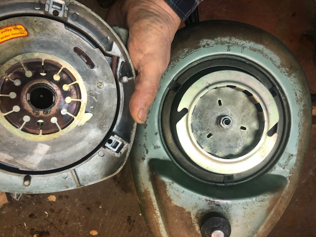 |
| Here you see under the flywheel, which is very clean, the coils, points & condensers |
|
|
|
Here
is the carburetor from the front |
Here is the carburetor
from the RH side |
 |
 |
| Here we see the simple shifting reverse interlock |
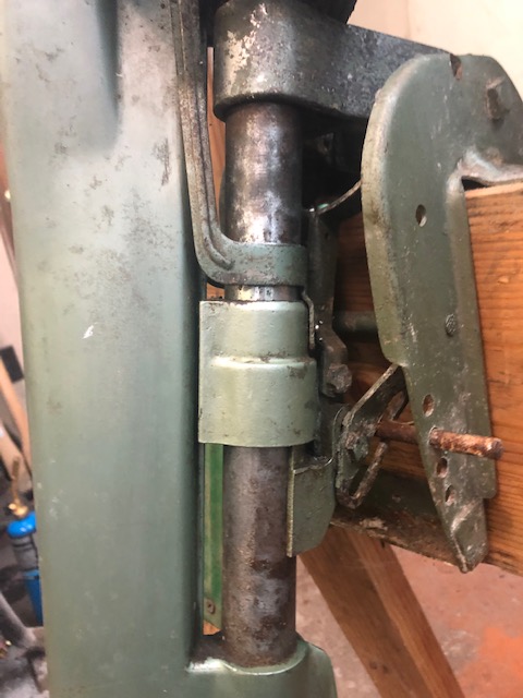 |
| Here you see the result of my screw up |
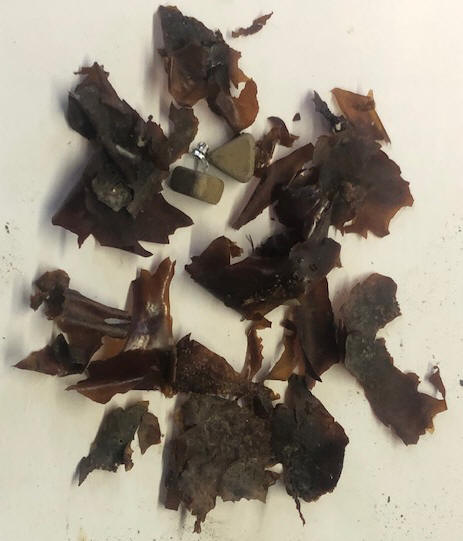 |
Water Pump Repair ; Here is an excerpt from the factory service manual. SHIFT MODEL WATER PUMP The water pump is a positive rotary vane type impeller made of special synthetic rubber, which rotates in a stainless steel cavity. Both the impeller and the cavity are replaceable, but this is seldom necessary. Operation in even the most sandy water will not appreciably wear down the cavity. When installing a new impeller, make sure that it does not bind over the pump drive pin on the driveshaft. If the impeller binds, the edges of the pump pin should be filed slightly to allow the pump to float on the shaft. The lower pump seal should be replaced when installing a new cavity and the cavity should be held in place with Duco cement
Since this motor is now 70 years old and has sat for a unknown number of years, the condition of the water pump impeller being unknown and replacement parts are not readily available. AND whereas water flow is critical on all water cooled outboards, it seemed prudent to replace this impeller while I now have it apart. There is one person who caters to these motors, but he only offers an exchange of the old impeller (reusing your old hub). To accomplish this, I ferreted out his name and sent an e-mail, then got this simple reply the next day. He can be reached at 'Baron0418@att.net'
, Send me your old impeller, $27 Cash, check or Postal MO to Brian Wilcox 9231 Stone Rd. Algonac, Mi 48001.
I sent him $30 cash and got the new impeller within 10 days.
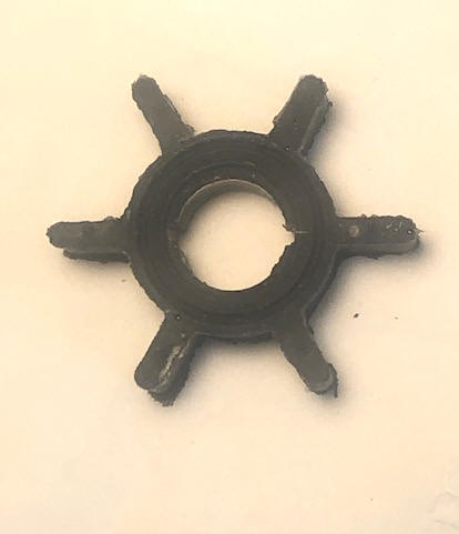
This obsolete water pump impeller #493-5100 uses 6 vanes, with dimensions of the pump liner being 1/2" hole, .500 thick and the liner being 1.500" ID. While measuring the new impeller, it was .593' thick and 1.600" OD. This impeller has key slots on both sides of the hub at 180 degrees to each other.
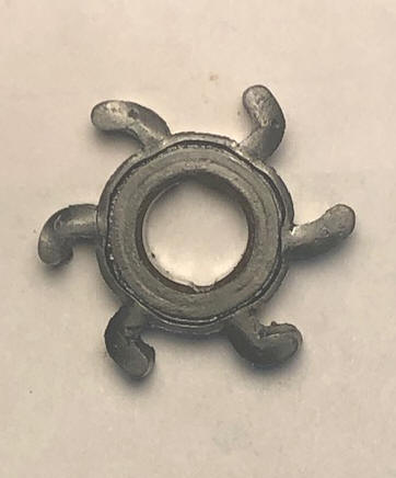
In the photo below, this badly deformed impeller is probably the original to this motor. Here the vanes have taken a set to where it would be unwise to rely on it, as the vanes now do not have enough of a diameter to even contact the widest part of the cup, very badly restricting the proper functioning.
| Here we see a very badly deformed impeller | Here we see the new replacement impeller |
 |
 |
OK, now disassemble the lower unit and get into the water pump. This lower
unit is different
than the many others that I have dealt with in the past 50 some years of
outboard motor tinkering. These
lower units have a nose cap for the gearbox that is screwed on, using 3 machine screws
(2 small #10 on the sides and a 1/4" on the bottom). This cap is the front part of the gearbox, so in removing
it, you also expose all the gears AND the gear oil as well, if you have not already drained
it. It was pretty obvious that this oil was probably original, as it
looked more like BLACK tar.
Shifting
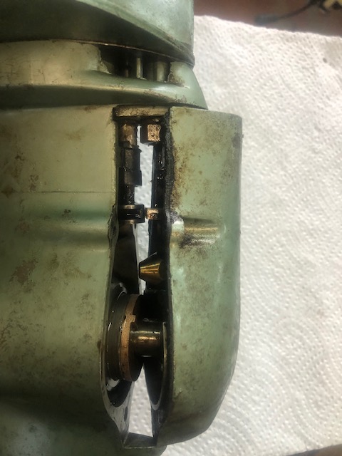
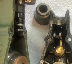
; The shifting mechanism works vertically and is located in the front
of this cap. It has a small metal fork that slides into a round threaded
1/4" connector button on the bottom of the shifting rod. This button, being threaded can be
adjusted, but on this one, the bottom of the button was flush with the bottom
end of the shifting rod, which is what the manual lists. This button has to be removed to allow the
shifting rod to slide up and out of the lower unit. This button has 2
slots (one on each side) that mate into the fork sides horizontally, making an
easy slip in connection to remove the cap.
I did not take dimensions when I had it apart, and I think the threads were 1/4 X 28 NF. To make one, you could braze/silver solder 2 nuts together (on a bolt for thread alignment) then file slots in the center on each side to allow the shifting fork to slide into. Note -- it is limited to overall height, otherwise the rod will not raise high enough to engage the gear.
| Here we see the shifting connection in the gearbox nose cap visible just above the screw bosses | Here is a blown up view of connector button |
 |
 |
Gearbox ; Now to remove the gearbox, which was by removing the (2) 5/16" nuts (1/2"
wrench) off the studs mounted in the lower exhaust housing and under
the cavitation plate. This allowed the gearbox to be slid down
and supposedly off, as the
driveshaft is withdrawn down and out of the exhaust housing exposing the water
pump. This one did not allow the upper driveshaft to
come down and out, which complicated reassembly.
So, to access the internals for further disassembly and to get the impeller off, I had to clean this old gear oil out, because on this model the lower end of the driveshaft, being square, engaged the square hole in the drive gear and was held in place by a horizontal cotter pin through the gear and the shaft (hid in the gear oil). This would have been about impossible to detect without referring to the service manual.
Disassembly, with the nosecone off -- (1) Remove the prop and pull the prop
shaft and gears out toward the front. (2) In order to get the driveshaft cotter pin
out, you have to rotate the driveshaft AND drive gear enough to be able to close
the ears of the spread out cotter pin, located in the upper base of the drive
gear. You can not rotate the shaft fully because there is not enough
clearance behind or sides for the extra length now of the cotter pin. So move it back AND twist off both tails of the cotter
pin. Now rotate it 180 degrees and using pliers, pull the now broken off/shortened
cotter pin out by it's head.
If you could raise the top wear plate and the impeller on the drives shaft, with the prop
shaft out, you should be able to drop the
driveshaft, BUT NO, because of the impeller key/pin is too large to pass through
the top stainless steel impeller plate, so it is locked in place. So with
the drive gear off the shaft, separate the parts enough to remove the impeller
key. Now the gearbox can be removed.
Since replacement parts are virtually non existent, the gasket between the gearcase and the front nose cap had to be made out of bulk gasket material.
While this motor this far torn down, it may be wise to see if I can also replace the propeller shaft seal. Partly because of it's age and then when removing the prop, there was over 12" of old cuttyhunk line imbedded into this seal. Upon close inspection, I find a name and part number on the rear of the existing seal. Victor 62004, which now gives me the chance to cross reference it to a more common brand used currently. Thus another trip to my friendly local auto parts store, but no cross-reference was available. So I measured it, the prop shaft was .500" with the OD of the seal being 1.000" and as close as I could measure while it was still pressed into the housing was about .312" thick. This was probably common 70 years ago, but now most all bearings and seals are metric. I did find one that had the main dimensions OK, but a tad bit thinner, which should not be an issue.
On final assembly this motor, it is better than some others, in connecting the water outlet from the water pump to the tube leading up to the powerhead. There is no blind guessing of fishing up inside the exhaust housing here for tube connections, as the outlet is built into the housing whereby there is no guessing when everything bolts together. A plus here.
Shifting ; On
many motors the clutch dogs on the slider are rectangular, fitting into a
slightly larger rectangle hole in the forward/reverse gears. This makes
for a solid engagement, BUT (if the motor is not running) and you try to shift,
your chances are slim that they will engage. This also causes broken
shifting handles if the owner does not read or understand the situation.
It also causes the leading edges of these dogs to (over time when shifting while
running at a higher RPM) to become worn, creating a situation where they will not hold securely and
the motor can jump out of gear if under load. However on this
motor, the dogs are a type of ratchet, making for smoother shifting at any
position, and minimizing chance of wear.
Reassemble It ; You will note that there are some hardened bronze thrust washers inside the gearbox. These has "ears" to engage corresponding notches in either the gears or housing. These bronze thrust washers in front of the needle roller bearings have projections that must fit into slots in the housing to prevent the thrust washer's turning. If improperly installed, damage will occur to thrust washer and bearings. The front and rear washers are different as explained below.
In reassembling of the gearbox,
(1) Install the shifting rod grommet in the appropriate hole in the
cavitation plate, slide this plate onto the drive shaft (2) Slide the
top wear plate onto the drive shaft, (NOTE) the word "TOP" on it.
Clean and re-install the water intake screens in the front of
the housing. (3) install the stainless steel top water pump cover (TOP)
side up. (4) install the water pump impeller onto the
drive shaft, and slide them up out of the way. (5)
Install the rear thrust washer engaging the 2 outer ears that do not extend all
the way into the center prop-shaft hole (TIP HERE, grease the
rear surface with trailer axle grease) which helps stick that thrust washer so
it will not slip during the other process and you can later then install the
prop shaft easier. (6) Now the impeller can be pushed
down, aligning on it's drive pin (.092" X .565").
(7) Now with the drive shaft down enough to install the drive shaft thrust
washer and drive gear in position the bottom square of the driveshaft, (aligned
to match the shaft cotter pin hole. (8)
Put in a new cotter pin (3/32" X 1 1/4"), rotate the gear and spread the cotter
pin tails into the groove of the drive gear. (9) Then
rotate the impeller vanes in the proper RH rotation into the water pump
housing and slide the upper water pump plate and cavitation plate up against the
exhaust housing. (10) Slide the lower unit
assembly up into the exhaust housing, feeling for the crankshaft spines with the
driveshaft. You may have to rotate the flywheel slightly before you get
them, aligned. Once the shafts are aligned, (you can tell by with it in
gear, buy turning the flywheel), the gears will be turning (11)
Install the (2) 5/16" nuts on the exhaust housing studs
(12)
Install the reverse gear bronze thrust washer (centered), these ears are shorter, not going
all the way into the center prop shaft hole ( grease this washer with boat
trailer grease to help hold it in place while you work on the rest) to ensure
this washer stays in place, if the washer gets out of place, you may well have
to go back, disassemble and then reposition the thrust washer. (13)
Install the reverse gear. (14) Install the prop shaft.
(15) Install the forward gear. (16) Then finish installing the forward
bronze thrust washer in the nose cap, again, smearing some boat trailer grease on
the front mating surface to hold it in place).
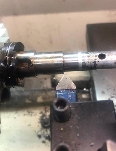
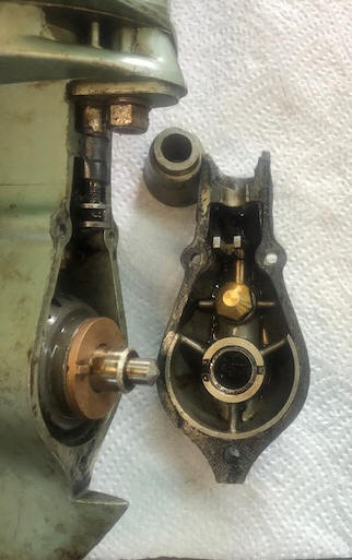
In the LH photo below, you see a simple lathe operation being performed to
facilitate installing the prop-shaft if the inner bronze thrust washer is
slightly misaligned.
|
Here we see the sharp shoulder edge being slightly broken to a taper on the outer edge |
Here is the relationship of the nosecone/rear gearcase (the hub between the parts is only for the support of the nosecone for the photo) |
 |
 |
The gasket
between the gearcase and the nose cone was made from .025" thick gasket
material, by laying the material on the nosecone, getting a good
impression (best when there was a slight amount of old gear oil) then
judiciously cutting away what was excess with scissors and a sharp knife.
Just before final assembly it was Permetexed onto the nosecone to maintain it
remaining in place adding to it's stability.
Propeller ;
Here is an excerpt from the factory
service manual. SLIP CLUTCH PROPELLER
As additional protection to the drive and propeller shafts and other mechanism of the motor, a stainless steel shear pin is used to position the propeller on the propeller shaft. If this pin shears, the motor will run as if in neutral, regardless of what gear it is in. The motor should be shut off immediately, the propeller removed, and the pin replaced.
This clutch was simply 2 opposing hardened aluminum cones (male/ female) with a
.056" plastic sleeve that fit between the inner cone and outer (being the inner
part of the prop).
Just tighten the prop nut for your slip adjustment. However, in the short time
that I had this apart, this plastic
showed signs of deterioration (like chunks falling off if
even slightly bumped).
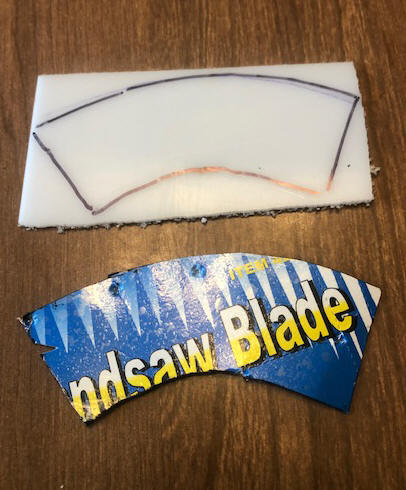
Here I ordered a 12" square X 1/16" (.062') thick piece of Delrin,
which I then made a template out of thin cardboard of a
similar thickness to fit in
between the two, then transferred those dimensions to the Delrin, providing a
start for a new slip clutch.
This process had to be done in steps. Working this plastic was accomplished by
cutting the material out using a metal bandsaw, heating the material somewhat
using a electric heat gun to get the new material bent enough to get it into
the female part (the prop). Then by heating everything, (the material, prop and
inner cone
As seen in the LH photo below, the
dimensions are 4" overall tip to longest tip, 3 3/32" for the shorter overall,
| Here we see a light cardboard fitted pattern & the layout on new material | Here are the old plastic clutch, and the new one |
 |
 |
The good one thing here, was even as I had to get this new clutch
material a bit thicker, or the original had been worn down
(.007"), or if placed differently in the prop, the prop nut cotter pin was an easy fit
because the hole in the prop shaft was not a single hole but a slot clear to the
rear of the threads on the shaft. Thereby making for an easier cotter pin
alignment if the new clutch took up more space because of it's slightly thicker
material.
Convert to a Flushing System ;
While I have it this far, after reading the service manual, which gave diagrams/dimensions on how to modify the lower unit to use a modern threaded adapter to flush/run the motor using city water and a flushing adapter to a garden hose, seemed like a good idea, but alter it to use the 3/8" threaded adapter currently used on many motors to flush them. From the service manual, it gives the exact location to drill/tap/modify the lower unit below the water pump intake to where I am able to utilize the later screw in flush adapters on this motor. After inspection of this gearbox housing, the factory recommended location for drilling for this adapter is in a drain cavity for the water pump to keep it from freezing (and breaking the housing) during COLD weather.
Mercury sells a flushing adapter that uses a 3/8" National Course bolt thread on one end and a female garden hose end on the other, as seen in the photo below.
Mercury's Quick-Silver part number is # 24789A1 for the brass version @ $26.68 with the actual name being "Flushing Device". Also OMC Johnson/Evinrude uses the same adapter to back-flush for many of their outboard motors made from 1993 to 2007, but for some reason it is not readily located on their parts listing. These adapters also fit about all of the Japanese outboards that use a back-flush system.
| Mercury Outboard Flush Device #C-24789A 1 |
|
|
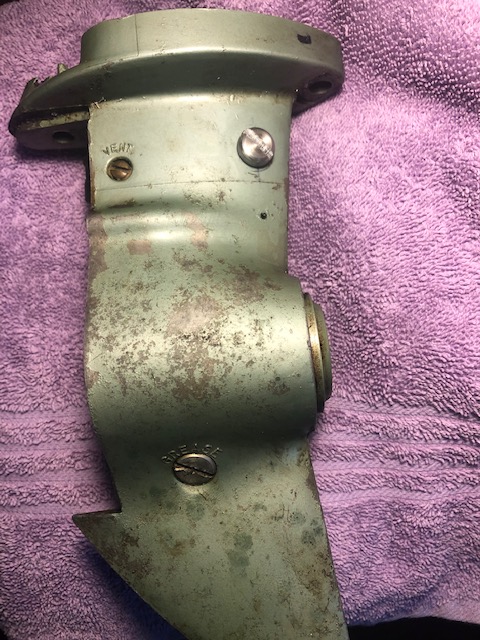
In the photo below, you can see the small drain hole directly below
my new threaded plug. This plug was made from a
stainless steel 3/8" X 3/4" hex head bolt that was modified in
my lathe for a lesser protrusion and a screwdriver slot then cut.
The threads were also shortened to about 3/8". And there
probably needs to be a thin Nylon washer under it, not to seal the
cavity, but to keep the plug screw from loosening. OR,
you could purchase OMC drain/vent plug and washer, or
the Sierra Marine equivalent #18-2387 - Drain Plug Slotted, and #18-4248 -
for the Washer.
| Here we see the flush modification |
 |
Finished Product ; I was glad that the powerhead was still in good enough shape that I did not have to delve inside it on this project. A very welcome situation.
The good part about this whole project was that I never broke off any stuck/seized bolts. The design was simple but effective, as to producing a high grade, economical product. (Which in some cases can be too simple and frail). And it just proves that even at my age of 85, and with many of these restoration projects under my belt, I still learned a few things.
Now the question is do I try to find a matching paint AND new decals? The paint should not be a real issue, however the decals are another story as this size and year if motor appears to be very specific to itself. And there are probably not a lot of these motors out there, especially in a good enough condition to copy the decals from.
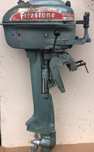
Therefor, I finally decided to leave it as is, It does not look bad from a distance, but up close she shows some evidence of it's 70 years of age (a few wrinkles, but no broken bones), mainly the paint shows it's age and some rust on the top of the fuel tank. But by and large, a good representation of years gone by. And it will push my also restored 1968 12' aluminum skiff along nicely just the way it is. It may even bring back memories on a sunny afternoon on a local lake.
| Here we see the finished project |
 |
R
Recommended
Fuel / Oil Mix :
The
reason for mixing oil with the gasoline is to lubricate the inside of these 2
cycle motors. The formula for the ratio was/is governed by the internal
construction of the bearings, mostly the connecting rod bearings. In early
years all bearings were bronze, and requiring more oil in the fuel mix. As time
and engineering improved, the rod bearings transgressed to needle bearings.
The main bearings also changed to either ball or Torrington caged needle roller
bearings, which could be slid onto the top and bottom of the crankshaft.
The bug here was the center main bearing, as it needed to be split to fit onto
that crankshaft journal. Some still use bronze for the center main, but
others use loose needles. Loose needle bearings work, but are have an issue
installing them correctly. Essentially the more ball/roller bearings
the motor has the less oil it needs. If you run a old bronze bushing
motor that was designed for 24-1 mix on the newer 50-1 mix, in all likelihood in
a short period of time, the connecting rod bearing would not be lubricated enough
AND it will seize onto the shaft, usually breaking the rod and sometimes before
the rotation stops, it can blow a hole in the block because of the rod now
flopping around with not any spare room for it.
The formula shown below will be on all modern 2 cycle oil sold
in the last 50 years or so. On most all of the pints and quart plastic
bottles ofTWC-3 oils there will be a narrow clear vertical
window on the edge of the bottles. On the sides of this window will have
numbers representing Ounces and Milliliters for other parts of the world.
Or you can purchase special measuring containers showing different ratios and
the amount of ounces needed.
If your motor is to where you have to mix the oil,
you need to know how much gasoline you will be needing, add the oil before you
fill the fuel tank so that the oil mixes better that just dumping it in after
you fuel up. However if that is not possible, guess, then add a majority of
what you think it will take, fuel up and then add the rest matching the amount of
gasoline you took on. If you are using portable fuel thanks, before hand,
when you fill it, add 1 gallon at a time, use a clean 3/8" or 1/2" dowel, mark
the dowel at each gallon and use it as a measuring stick. This way you can
refill a partly full tank with the known amount of oil.
A quart has 32 ounces of oil in it. So for a
portable 3 gallon tank normally used on these smaller motors, to fill it using
the 50:1 ratio would take 8 ounces, (1/2 pint) or 1/4 of the quart.
|
FUEL MIXING TABLE |
||||||
| Gallons of Gasoline |
Gasoline to Oil Ratio |
|||||
|
Ounces of Oil to be Added |
||||||
| 16:1 | 24:1 | 32:1 | 50:1 | 75-1 | 100:1 | |
| 1 | 8 | 5 | 4 | 3 | 2.5 | 2 |
| 2 | 16 | 11 | 8 | 5 | 4 | 3 |
| 3 | 24 | 16 | 12 | 8 | 6 | 4 |
| 4 | 32 | 21 | 16 | 11 | 8.5 | 6 |
| 5 | 40 | 27 | 20 | 13 | 10 | 7 |
| 6 | 48 | 32 | 24 | 16 | 12 | 8 |
After getting it running and the carburetor adjusted, it starts on second pull. To be sure that it would run on my on the water fishing trip, once I got it warm and set at an idle (trolling speed), I let it run in my test barrel for 1/2 an hour. It then was used on a fishing trip to Riffe Lake, pushing my 12' StarCraft aluminum boat nicely.
k to the Ramblings Home Page
Copyright © 2021 - 2023 LeeRoy Wisner All Rights Reserved
Originated 12-28-2021, Last updated
10-10-2023
to contact the author click here
#462-3602 Steering Handle Rubber Grip