|
Converting Johnson/Evinrude 9.9/15hp to Front Shift |
|
|
|
Converting Johnson/Evinrude 9.9/15hp to Front Shift |
|
|
How To Convert These Motors ;
We get used to things being one way or the
other, and that usually is not bad as far as familiarity. This for years
being for the
small to mid sized motors the
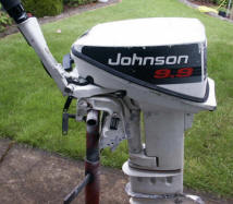
shifting lever has always been on the RH (Port) side. Same as for these
OMC motors, but in 1993 when the large block 9.9s came out,
they moved the shifting lever to the mid front. Some benefits??
Maybe.
This never really occurred to me before, then
with this newer version, along with Yamaha and Mercury also going the same route, (not
sure who was first). However when I got serious with a lake/river boat, (14' aluminum
StarCraft with a 1991 15hp Johnson) on it that, along with me being 88 years old along
with low back issues, it began to seem maybe they had something going here.
Then when I saw three different
conversions versions for this online, where all were using the
same principle of the same type of conversion, that simply bolted on these 9.9/15 hp
motors I got interested. So I saved a couple of photos, and this last winter, decided to
see what it would take to somewhat copy these conversions. With no
dimensions I was somewhat shooting in the dark, however it did not take a lot, just make
main pieces and work out the linkage between the two.
However I may have a slight advantage as I have been a machinist for nearly all
my life and still have a well equipped machine shop. My version was
slightly simpler in the linkage, but more complicated in the base plate than the
one in the photos. My reasoning for the later was that I wanted the pivot shaft
enclosed so it could be packed in grease and not exposed.
My reason for trying this conversion was, (1) there were no alterations to
the motor. (2) And in my small boat the rear seat was closer to the
transom so that I would have to twist around, or fumble to find the shifting lever on the
far side, all the while trying to maintain the trim of the hull for this boat.
And if this was on the river, where I may be making a drift, (with the motor in
neutral) but suddenly needed power, it may be a safety issue.
| Here you see the components of my front shift conversion |
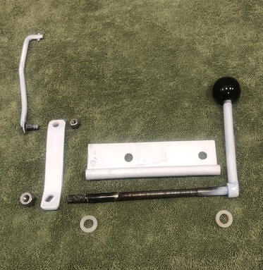 |
In making this, the hardest part was getting the slotted pivot shaft to upright arm a tight fit. I used a 1/2" mild steel rod, turned it down to 3/8" to fit inside the tubing that I had braze welded to the bottom of a 1/8" plate. This shaft had a head on one end and 3/8" threads on the other. The threaded end was milled so that it had a 1/4" thick centered flat. Then the upright arm drilled and filed to match the shaft flat.
I turned the center of
this shaft down slightly for 2 reasons, (1) for grease retention, and (2)
because in my welding the tube to the plate, it slightly warped the tube, so
this gave me a bit of reprieve in fitting. Well, I found that my flats
were slightly wider on the end than at the base of the threads, which gave some
sloppiness, so I added a dab of
brazing to the inner flat end, filed that down making the flat slightly tapered on the inner end, to
give me a secure fitting on the upright. It was easier to do this than
make a new tighter upright arm.
This base plate had to be shorter to the left (on the motor's
mounting base) enough for the shifting knob to clear the tiller handle as seen
in the photos below.
The handle was a 3/8" rod threaded on the upper end to fit a
plastic threaded knob. This handle was welded to the pivot shaft.
However if I was going to make another, I would simply thread both ends of the
shaft, weld a 3/8" nut to the handle so that where on final assembly, just position the handle
where needed and then weld the nut to the shaft. There are two (one
on each end) thick 3/8" Nylon thrust washers on the pivot shaft. All nuts
were stainless steel Nylock.
The linkage rod was made of 1/4" rod, threaded on the front Ell,
and with a 3/32" pin centered on the rear, in about 5/16" on the short Ell. This lock
pin was positioned on the linkage rod so they entered the original cable
shifting mounting hole, and then rotated 90 degrees secured this to the original
shifting lever. The length of this
rod can be done last as determined after fitting the other parts together. Here, you
need to fit it in reverse for the rearward movement of the handle knob against
the motor's front cowling is the limiting factor, as the
forward position has lots of room out and down.
I found that the 1/8" X 3/4" (it could have been 1/2' wide)
steel upright arm was about the right length with the holes being about 3 1/2" apart,
which line up horizontally with the original shifting rod's hole.
The base plate mounting holes were drilled to match the front
motor bracket which was factory drilled for mounting a cable steering attachment.
These holes on the early motors was 1/4", but enlarged on the later motors to
5/16".
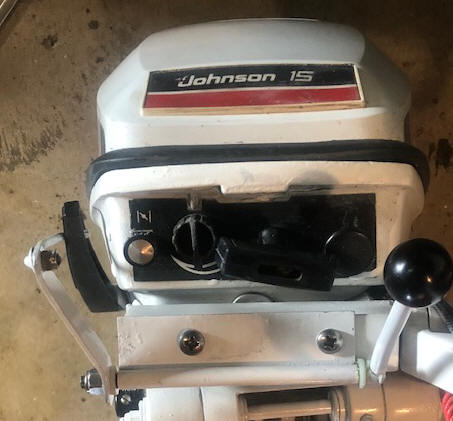
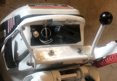
| Here you see the assembled unit of my front shift conversion | Here you see the assembled unit at a slight side view |
 |
 |
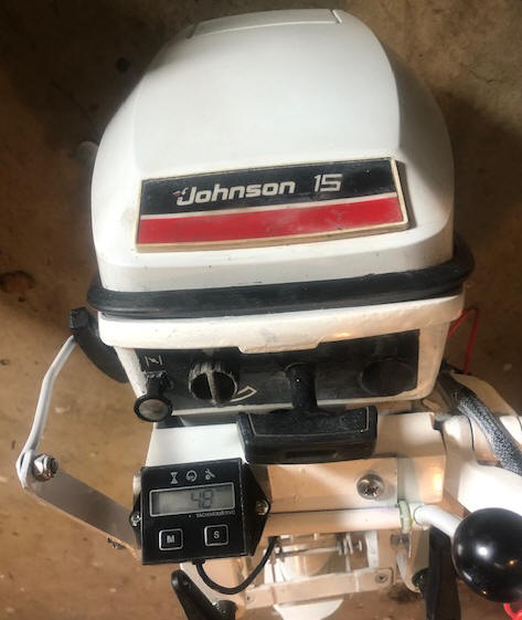
Then I used this base as a
platform for adding a small hour meter/tack. It is a compact fit, but
still gives me full view of the meter along with unhindered usage of all the front controls and starter handle.
This hour meter was previously mounted inside the cover
on the powerhead, which was OK, except I had no access to the tack while running
on the water. This is the type of unit that uses a single wire
which is wrapped around one of the spark plug wires.
| Here you see the mounting of my hour meter/tack |
 |
Originated 04-08-25, Last Updated
04-10-2025
Contact the author