 |
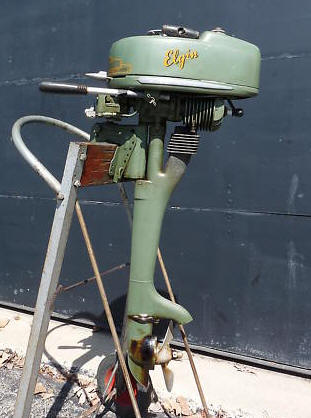
Awakening a 77
Year Old 1946 1.25 HP Air Cooled Elgin Outboard Motor |
History of Sears-Roebuck Outboard Motors
Sears-Roebuck got into the retail outboard business through
their catalog and stores about 1913 or 1914. At that time, it's Motorgo named kickers were
produced by a number of different firms in those early years.
Other names were also used over the years.
After WWII ended, Kissel
(who at that time was producing motors for Sears), was purchased by the West
Bend Aluminum Company, and Sears asked West Bend to come up with a new outboard
by 1946, that they named Elgin.
Here, Sears and West
Bend worked together to develop their outboard product line, one that fit the
Sears consumer's budget, lifestyle and Sears' guidelines for quality. They
were wise in using existing well known Wico magnetos and Tillitson carburetors. This relationship was highly successful
and profitable for 12 years with their agreement remained exclusive through
1959. It was this "Family" of apple green, small (1 1/4 to 7 1/2 hp) Elgin
motors from 1946 to 1959 that are best known today. The smallest one of
this series is what we will be working on here which were unchanged from 1946
until 1951.
My initial exposure to outboard
motors was a Johnson DT-38 4.2 hp when I was right out of high school.
But when the coils deteriorated and died, there was no real close mechanic, nor
any spare parts
available then, so I scrapped the powerhead, adapted a small 2 hp 2 cycle air cooled lawnmower
motor to the midsection and with this Frankenmotor and did get a bit of fishing time done
using it.
During this time, I found that one of the neighbors had,
when he got discharged from the military in 1946, bought a new Elgin 1.25hp
outboard motor. He never seemed to be a fisherman, so one day, I asked if
he was interested in selling it? No, he would use it some day.
Well as time went on, his wife divorced him, he later remarried, then later he
got real sick and was on Hospice. After his passing, I asked his 2nd
wife if that motor was still in hanging up his barn, and if she was interested in selling
it. She had no idea of what I was talking about, but her two older teenage sons quickly backed her up.
My guess was when he got sick, they went into his barn and quickly sold anything
that was loose without her knowledge.
Fast
forward 40 some years. One day online a old small pea green well used
outboard motor popped up for sale by the owner's son. No description
was supplied, (just Old Motor) but I recognized the motor as very akin to the one I had
earlier tried to buy. The price was listed at $100. I contacted dad
and my first question was "Is it seized?" Well Yes. "How long
has it been in this situation"? Probably 2 or 3 years and he was not
aware of that until it was put up for sale. When i asked to verify the model,
he said he could never find any ID. I offered him $50, and after a
long pause -- OK.
He was also retired and lived a
little over an hours drive from my place, but in a smaller town blending
into a larger city. With my deteriorated eyesight, I do not freeway or
city drive where I do not know the road/exits. However I made
arrangements to meet him nearer his home and close to a freeway exit, at a
Bass Pro Shop parking lot.
| Here is the BEFORE restoration | And here is the AFTER restoration |
|
|
Statistics For These Motors :
These are
Cylinders
1
Bore diameter
1.500"
Stroke 1.375"
Displacement
2.43 CI
Starter
manual independent rope
Bearings,
bronze bushings for the rods & lower main bearing, with needle
roller top main
bearing
Carburetor - Tillotson MD-1A with choke, throat dia. .562"
High speed jet, adjustable . Starting
point 1/2 turn out
Idle jet - Starting point 3/4 turn out
Fuel capacity - 3 1/2 pints
Fuel mix - Per gallon of gas, SAE-30 Oil
3/4 pt. for running, -- 1/2 pt. for trolling
Magneto - Wico
Point gap is .020"
Plug gap .040 " , Champion J12J or
RJ12C spark plug.
Flywheel key - .125 wide X .187 thick X
1.500? long, radius tapered on bottom
Flywheel nut - 7/16" NF, --
3/4"
wrench size
Transom Clamp - single screw
Gearbox oil - Waterproof boat
trailer grease
Gear
Ratio - 12 - 21
Prop. dia. & pitch - 2 Blade 6 1/2" X 5" LH
Prop shear
pin 5/32" X 7/8"
Prop
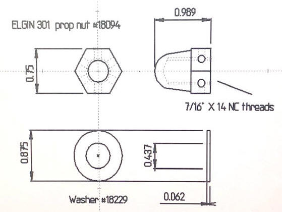
nut - 7/16" X 14 NC
Prop Nut cotter pin - 3/32" X 1"
Weight 19 1/2#
Upon getting it home, sure the paint was far from new and very little of
the decals left, but I was
pleasantly surprised to find that nothing was missing. From the
initial looking, the gas tank had a dent on both sides, but all the
carburetor parts were there, choke, knobs, fuel line shut off worked AND
the fuel tank was clean and dry. However, yes it had debris inside
the carb.
I pulled the spark plug, soaked the cylinder with some penetrating oil for an hour or so, then using a brass rod in the spark plug hole tapping on this rod and the top of the piston, IT MOVED slightly. I then put a socket on the flywheel nut and a breaker bar, it rotated. I then changed and used a electric drill motor on the socket and rotated it enough to ensure it was good and free. Then I took a compression test, 65#, not great, but should be enough to get it running. UPDATE -- after running it a few minutes this number increased to 86#. I replaced to spark plug with the correct one, and again using the electric drill motor, held onto the spark plug and promptly got shocked. It has fire, not a lot, but encouraging.
I then put some mixed fuel in the gas tank
and turned on the shut off valve. Lots of gas pouring thru the
carburetor throat. So next, tear the carb off and soak it in carb cleaner
overnight. The throttle lever to butterfly was seized, the same
shaft return spring was missing, which I found a replacement off a 2 1/2 hp big brother junker
carb. The carburetor main jet shaft was bent, here I put it in my metal lathe, rotating and tapping to get it
much straighter (like within .005"). The packing on this shaft was also so worn that I made a
new one using some plumbing Teflon packing tape. And of course
the main carb body gasket needed to be made from new cork material.
OK, got it back together, but still leaked a lot of gas out the carb.
Pulled the carb off and removed some of the internal new gasket that may
have been stopping the float from going all the way up and stopping the
gas flow when full. Still no start. But now it
sounds like it is starving for gas, so I removed the 3/16" fuel line from
the gas tank to the carb, and blew it out with compressed air (got some
debris out). Put it back together and BINGO it started.
Carburetor : This carburetor is a Tillotson model MD 1A. These carburetors very seldom need new parts other than gaskets which can be made from gasket material. The entire carburetor usually only requires a complete cleaning as did this one. These carburetors use a 2 part brass float that is soft soldered together. They have adjustable high and low speed needles.
The next thing was to remove the
carburetor, disassemble it, wire wheel brush most of the old paint and corrosion
or rust off the outside. Next was to soak the frozen shafts with
penetrating oil for a day. Once all the stuck parts were free, I cleaned
them and soaked them in carburetor cleaner solution overnight. The
butterflies were removed from the shafts, then the shafts were removed and any
debris on the shaft removed, cleaned and reassembled. It is very important to clean the idle tube thoroughly if you intend to troll
with this motor. This idle tube (as seen on to in the RH photo below) can be
removed from the top of the carburetor with a screwdriver. Soak it in the
solvent or cleaner, wash the cleaner off with HOT water, and blow this very small passageway hole in the tube out with compressed air.
The float needle seat had a slight groove in it
BUT when during the final sub-assembly by blowing on the carb fuel inlet
fitting and twisting the lower part of the carb to open/close the float,
the needle did shut off air flow, so maybe it is OK. WRONG --
so now need to look into finding a replacement float needle.
Which I found in the cannibalized 2.5 hp old carb, which had the same size
needle. But
after changing it and checking the float for adjustment, is still leaked.
BINGO -- DUMBY, when you made that new gasket did you check clearance for
the float? Probably too thick internally and restricting full
movement of the float to shut off the fuel flow.
| Tillotson carburetor |
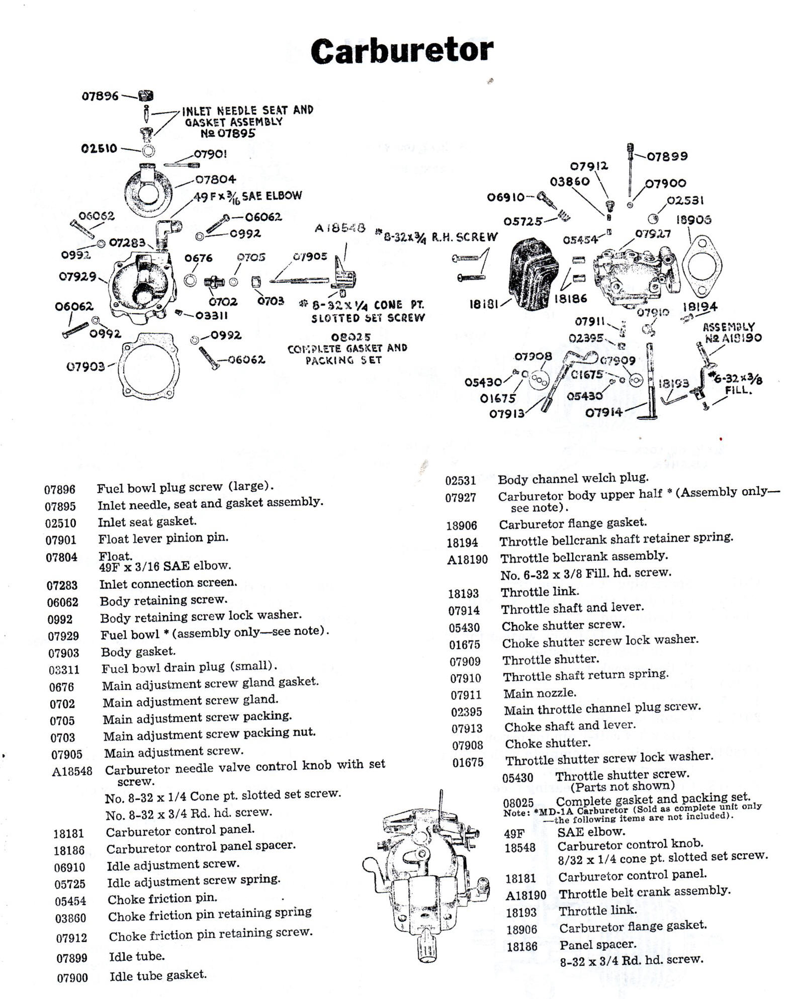 |
After getting it running, and with the main jet adjusted for a good high speed run, this knob only requires very little rotational movement to tune it for start/run/idle (just about the distance of the knob pointer to the farthest mark on the cover --NOT all the way to the stop location). Considerably less than the 2.5hp that I have known for MANY years. But in thinking about it this is a VERY SMALL motor, so requires less fuel.
| Front view of the carburetor, notice the throttle arm adjustment rod screw on the upper right, choke lever on left | RH side view of the carburetor, notice the idle adjustment knob top RH front, & high speed jet knob protruding to the right below |
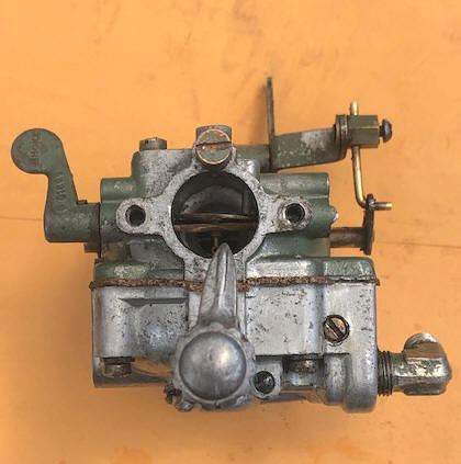 |
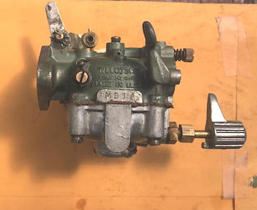 |
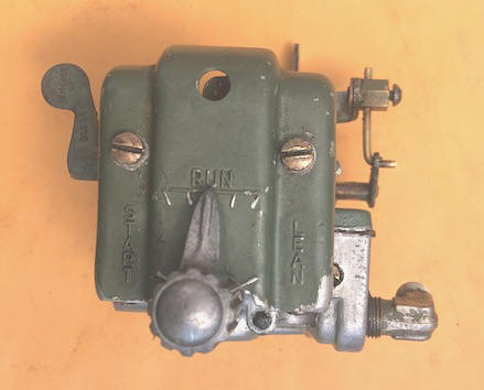
Carburetor Front Cover :
There
is a stamped out aluminum carburetor cover that is attached to the front of the
carburetor by (2) #8-32 X 7/8" long screws. This cover is held in place by two
stand offs 9/16" rubber bushings (old fuel line) off the front of the carb.
However these bushings have taken a set and do not position the cover properly,
so I found some new 1/4" round aluminum stand offs 3/4" long (and cut them to 5/8").
This distance
is somewhat critical, as it positions the high speed needle's knob
bottom lug at stops built into the cover to limit the knob's travel.
This cover has embossed into the face of it START, RUN, and LEAN for the main jet knob indications. This main-jet knob pointer needs to be adjusted after running to align with these markings on the cover.
| Front view of the carburetor cover |
 |
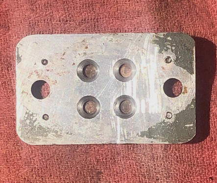
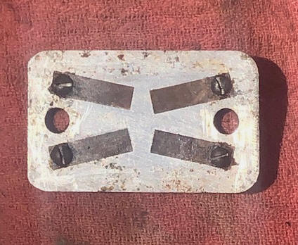
The carb to manifold gasket was still in good enough shape to use for
a pattern to make another one of those. The reed valve plate are directly
behind the carb and held on by the carb/manifold bolts. The fuel flow is through four
.177" round holes that are counter bored /tapered from .300" in the
front of the
plate.
| Front view of the reed valve plate | Rear view of the reed valve plate showing the reeds |
 |
 |
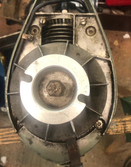
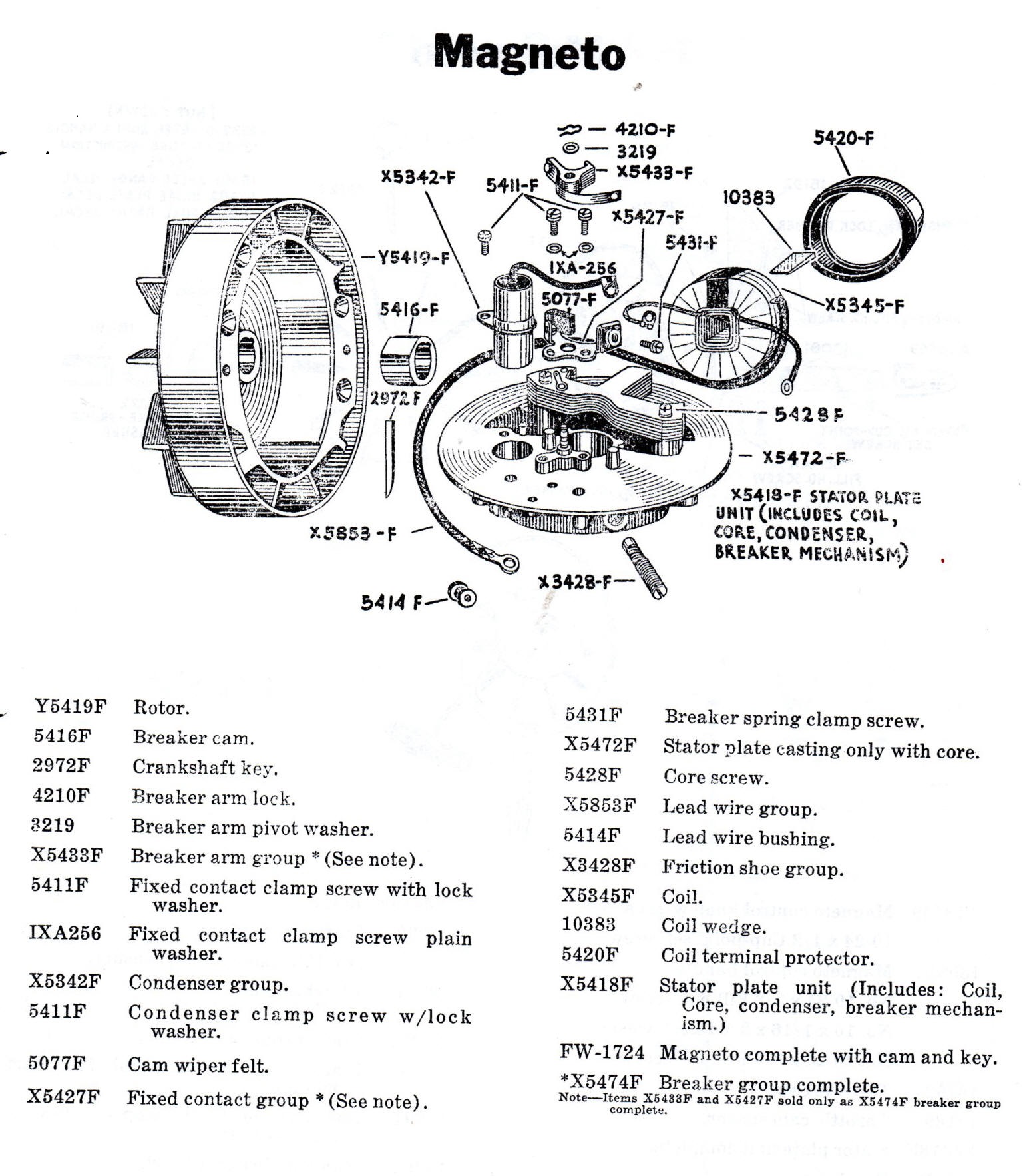
Well, with going this far, I might as well go through the magneto, cleaning any rust on the coil or running a point file through the points to remove any oxidation.
| Here you see the gas tank removed showing the top of the flywheel with the cooling fins |
Here the flywheel has been removed showing
the magneto, points, condenser & coil |
 |
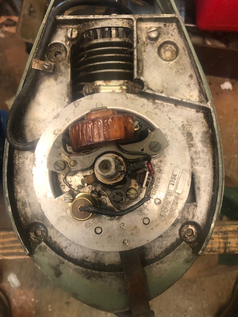 |
| Wico magneto |
 |
Powerhead
:
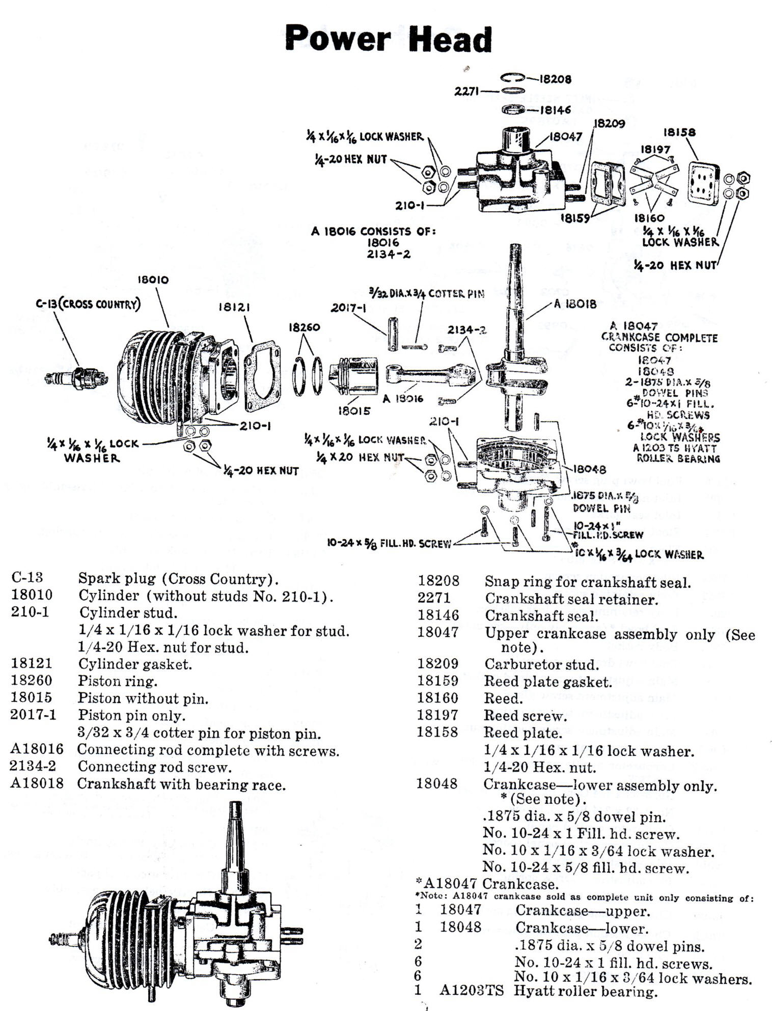
This powerhead is a
single cylinder Air Cooled 2 cycle, using a die cast aluminum block.
The cylinder itself has a steel liner
liner cast into it at the time of manufacture. As with many small 2 cycles, it does not have a removable head. The
connecting rod uses cast in bronze bushings for both the crankshaft and
wrist pins. It also uses cast in bronze bushings for the lower main
crankshaft bearings. The upper main crankshaft bearing is a needle
roller bearing.
| Powerhead |
 |
No
Thermostat
:
Since this motor is Air
Cooled, there is no water
thermostat. The temperature of the motor is maintained by cooling fins on
top of the flywheel, and cooling fins on the cylinder walls/head.
Starter Spool & Rope : The stamped out aluminum starter spool is bolted onto the top of the flywheel held in place by a internal star washer under the flywheel nut. There is no spool top plate as with the 2.5hp model.
The rope used here is
basically what is currently used as a emergency start rope on the small to
medium sized motors today. Most of these will be a
3/16" diameter, about 36" long with knot in one end and a wooden handle long
enough to grasp on the other end.
Fuel :
The
owners manual has it's recommendation
-- Per gallon of gas, SAE-30 Oil 3/4 pt. for running, -- 1/2 pt. for
trolling. Yes, but that was in 1946, and it would still work, but
technology has changed (and for the better). You will now see for about
all outboard motors the recommended oil is outboard TC-W3, which is designed to
be a more of a detergent type, which helps eliminate internal carbon in the
motor. Well that may well be fine, BUT on these AIR COOLED motors,
which run much hotter than all their water cooled cousins, it may just be better to
move over to chain saw oil, (which is designed for air cooled engines that
normally run at a full speed). Stihl sells their own oil, which in my mind
would be ideal to run in these little gems.
Fuel Tank : The fuel tank is made of two stamped out aluminum halves welded together into a teardrop shape. Total fuel capacity is 3 1/2 pints. The fuel line outlet (3/16" copper tubing) is on the LH rear with the line running under that edge of the tank forward to the same side of the carburetor. Inside the tank, this fuel outlet has a VERY FINE screen that acts as a strainer. There is a shut off fuel valve about in the middle of this line.
Fuel Filler Cap : This knurled edged cap screws into the gas tank and has a smaller knurled vent screw center top. The seal under the main cap is a 3/32"thick X 7/8" ID X 1" OD Neoprene O Ring. Under the vent screw is a thin Nylon washer that seats against a small hole under it's head. This washer needs to be large enough that when the vent screw is tightened down that the washer covers the vent hole, then seals it. The cap assembly may need to be disassembled, cleaned and the vent hole verified as being open. This vent screw needs to be unscrewed slightly when the motor is in the run mode, but tightened down for transport to prevent fuel leakage. The Vee shaped brass spring that is attached to a couple of chain links inside the tank that retains the cap when unscrewed, may over time become brittle, then break. A new one can be fabricated out of 1/16" brazing rod by using needle nose pliers.
| Fuel tank and steering handle |
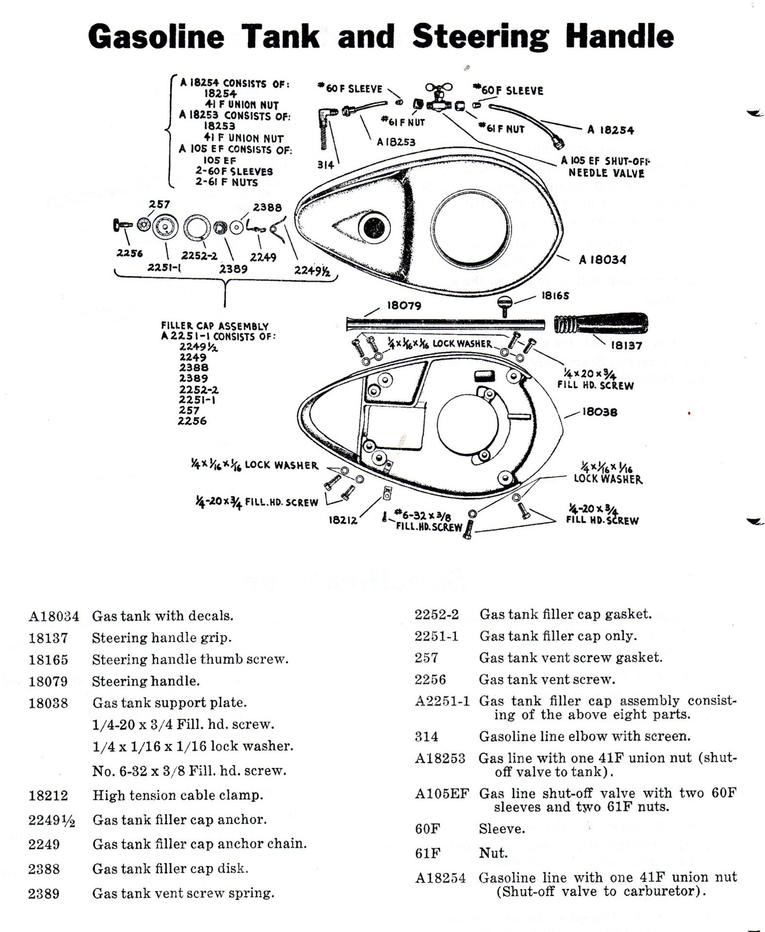 |
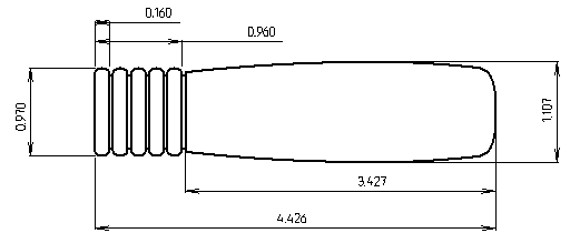
Tiller Handle : This is simply a 1/2" OD heavy wall aluminum tube 14 1/2" long that is slid into a socket on the LH side of the motor gas tank bracket and is held in place by a clamp type wing screw. The front, "handle" is a small rubber type bicycle handle bar hand grip to match the tubing. Reproductions of this grip are available from https://www.ebay.com/str/bigrichsoldoutboardparts "NEW Vintage Antique Tiller Grip Outboard Motor FITS Elgin 1/2" ID X 3-3/4" Long $15.00".
| Early type rubber tiller handle end dimensions. |
 |
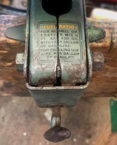
Fuel Mix Ratio : Printed on a decal on the motor clamp bracket is written "For normal operation, mix 3/4 pint. of SAE # 30 oil with each gallon of gasoline. For trolling use 1/2 pint per gallon of gasoline" which would be (32-1). It is not known why the modification in the fuel mixture unless there were complaints of the spark plugs fouling a lot when trolling, which these motors were probably used mostly for.
Instruction for Starting :
Also
printed
in a decal on the lower front of the clamp bracket above the clamp screw
is instructions for starting. "Open the vent on filler cap, open gas line,
valve, move both carburetor & magneto levers tostart position. Pull
choke lever forward, wind rope on starter plate on starter plate clockwise
& pull to start motor. When motor starts, push choke lever up, move
carburetor control to best running position, move magneto to speed
desired".
| Here an original decal showing the fuel ratio mounted on the clamp bracket |
 |
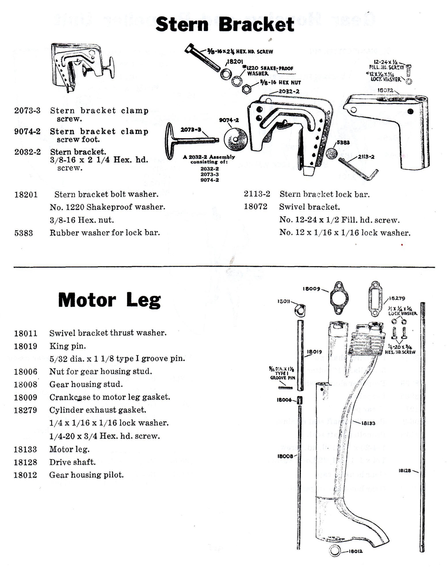
| Stern bracket and midsection |
 |
One interesting thing on these motors is that on the lower section of this 'Leg" you will see a cast in 1/8" ring/ridge around the periphery of the housing 3 1/2" above the juncture of the gearcase unit. This is the suggested water level of the motor.
Transom Clamp Bracket & Motor Tilt : The clamp bracket is made of steel which uses a single twist type Tee steel clamp screw to attach the motor to the boat transom These motors do not include any provision for a partial tilt or full up retention of the motor when not running. But they can be adjusted for side tension to some degree, where the tilt pivot bolt is 3/8" using 9/16" wrenches.
Tilt Pin : This is one thing that may get lost over the years. This pin is actually called a "Lock Bar" by the manufacturer. This pin can be positioned in one of 6 different holes on the transom clamp bracket that allow the motor to be tilted and rest against this pin to allow the motor when running to be leveled when on the boat. As a loss prevention, a 3/4" X 1/8" tight fitting rubber washer is provided that just slides over the outboard end as a retainer.
The original pins were made of 3/16" rod bent into an Ell shape, with the short end (handle) extending 1" with the support part of this pin 2 9/16" long outside measurements. On the long end there is a narrow protruding wing/ear that mates with the keyhole type slot that this pin goes through. This wing is on the on the same side of the pin as the handle and is positioned horizontally so it exits the hole on the far side of the bracket. In use, the pin has to be rotated upward so the wing enters the mating holes and then when the handle is rotated down as it will finally be because of gravity, the pin is locked in from backing out.
| Original Tilt Pin |
|
|
Motor Pivot : Incorporated into the clamp bracket is the motor pivot unit. As designed this bracket DOES NOT allow the motor to be rotated completely around or 360 degrees, also you have no reverse on these motors. There are a screw that put tension on the main pivot shaft so if you need more tension it can be adjusted here. NOTE, since these little motors are only one cylinder AND when you use them at a very slow idle that they are capable of, they vibrate more with this pivot adjustment may need to be set tighter than normal. This would help you keep from having to have ahold of the tiller handle all the time when running this slow because the vibrating motor will start rotating sideways on it's own.
Exhaust Pressure Relief Holes : On the rear trailing edge of the exhaust housing above water level are 15 small holes of about 3/32" drilled thru into the inside exhaust cavity. These appear to be for back pressure relief, as with the motor is running slowly in the water and if you cover a majority of them up with your hand, the motor slows down indicating that the exhaust is being restricted. They also make it easier relieve backpressure and for the motor to breathe when starting. So it may behoove you to clean these holes up using a drill bit that just goes inside of them.
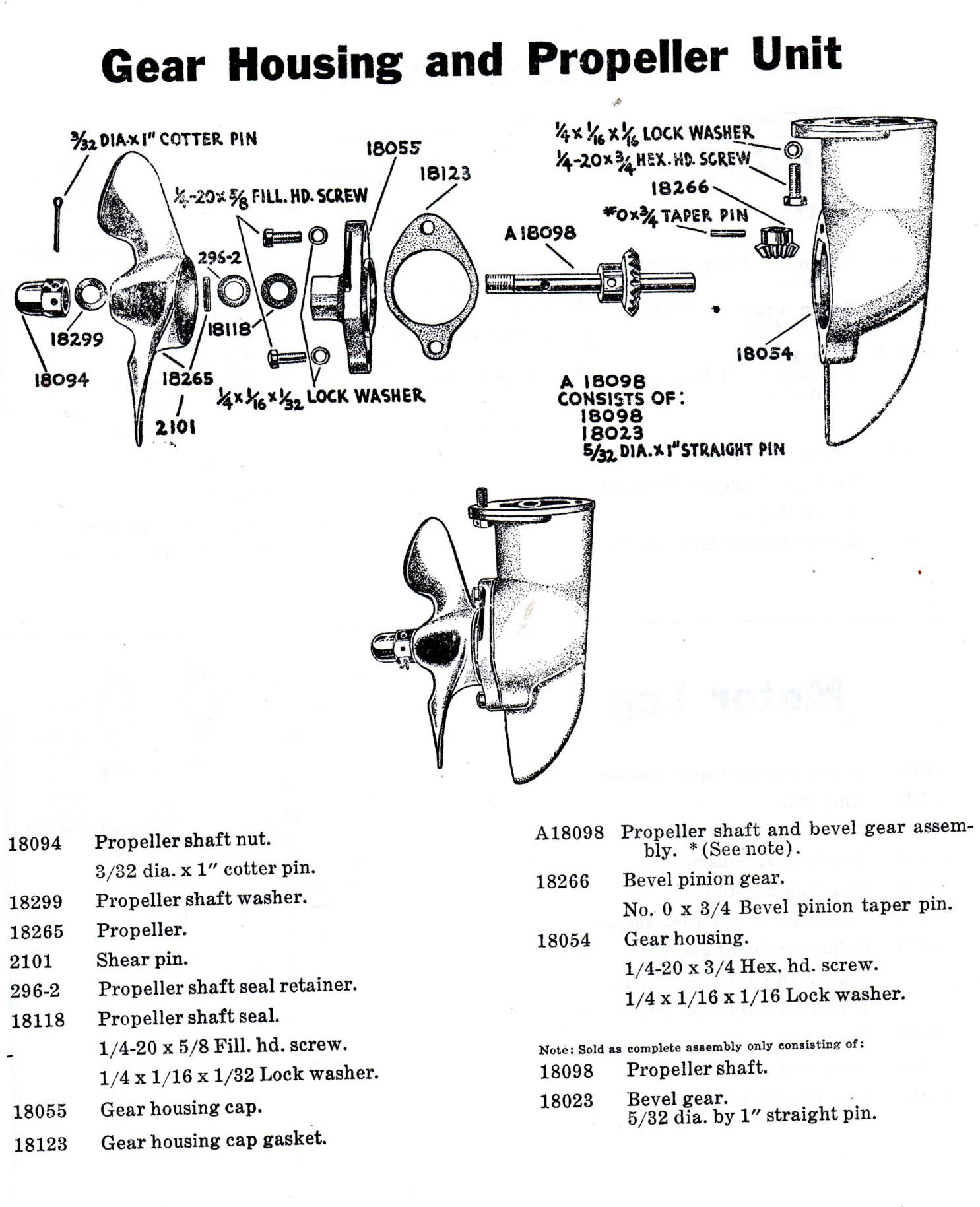
Gearcase : There is no reverse AND no neutral on this motor. The driveshaft and prop shaft run inside bronze bushings. All Elgin motors of this period were designed to use grease in the lower unit. You may not be able to readily locate Lubriplate #105 as suggested by one of the websites, however it should be available at most good auto parts stores like NAPA and others. Another grease can be Lubriplate #630 AA that is normally used in lower unit bearings for large outboard Jet type drive units. There is no fill or drain holes so the motor will need to be positioned with the prop shaft up, the lubricant placed into the gear cavity in volume. However I have found that if you leave out the prop shaft/gear force grease around the drive gear and cavity and lightly grease the forward prop shaft and front of the gear, then install the shaft/gears and then bolting the rear bearing cover in place works for me.
The prop shaft is 7/16"
dia., has a shaft seal #18118 , (.125" X .432" ID X .825").
There is no upper gearcase shaft seal, but simply a pressure thrust fit from the drive gear upper surface to the cast in bronze bushing, but with a grease in the gearbox instead of 90 weight oil and using a waterproof grease, it works.
Next will be getting into the gearbox. Here I found the gearbox totally dry of grease, however it had no evidence of water or rust. The gear ratio was 12 teeth on the driveshaft, to 21 teeth on the driven prop shaft.
The Owner's / Operators manual specifies after every 30 hours of operation to remove the gear housing cap and check for water intrusion.
| Gearcase and Propeller unit |
 |
Propeller :
The propeller is a 2 blade
6
1/2" diameter with a 5" pitch with a left hand rotation viewed from the
rear. The propeller was made by Alcoa Aluminum, has #18265 cast on it.
It was not painted, but left the plain bead-blasted aluminum color. The shaft hole is
7/16", uses a standard 7/16" X 14 TPI course thread acorn type nut with holes in
each flat for the retainer cotter pin.
The hole in the propeller shaft will accommodate a 5/32 dia. pin, but given the obsolescence of parts for this motor and low hp rating, I would rather opt for a safety factor here by using a smaller 1/8" dia. X .875" long shear pin. I like to make mine from brazing rod used for Oxy/Acetylene welding, they are tough, do shear quite well and won't rust.
Most of these old motors you will
encounter will have the propeller nut washer missing. The original washer
was probably steel. This may not be that important, but a replacement Nylon flat
washer with a 7/16" hole X 1" OD can be found at many well stocked hardware stores that
carry a bolt and nut selection. The best OD that fits but does not
restrict flow and blends with the rear of the propeller and under the nut and
measures 7/8", which can be cut down to from the 1" size.
The prop cotter pin hole in the prop shaft is not a single
hole, but a slot running lengthwise of the rear of the prop shaft.
Propeller nut cotter pin would be a 3/32" dia. by 1" long, and stainless steel would be preferable.
| Propeller cleaned | Prop nut & washer |
|
|
 |
.
Paint :
Replacement paint for the faded
out green
best match to be found was Rust-Oleum #7737 Satin Spruce Green. Do
not confuse this to XO-Rust or Krylon brands. (NOTE as
of 2-2-2008 this color of paint has apparently been dropped by the manufacturer, the closest
they now have is Hunter Green which is considerably darker). This Spruce Green
has been noted by some restoration experts as a very close match of several original motors compared to it.
Since the required matching paint is
no longer available, the next step was to take the head (probably the most
protected with original coloring left) off this motor, go to a paint store that
can scan it to reproduce a close color match. This color was mixed in one
quart X-O Rust neutral oil base using code B-42, C-23 and D-18 tint
colors which came out VERY close to my original color at a cost of about $10.00 a
quart.
This paint appears to need a slight amount of greenish color to match the spruce
green being recommended for a restoration project of these motors, however it matches the protected section of the head off the restoration motor.
So either color appears very close to the original. TIP :
If you get a paint mixed, have them write the code on the BOTTOM of
the can, not on the top, as the top will usually get paint all over it or will
rust over time while the bottom stays clean forever. I found that a
small touch up air sprayer works great for this painting situation.
The DuPont is the same clear coat that is used on modern base/clear automotive paint jobs, however these paints are expensive, need a air compressor and spray paint gun.
Any overcoat that you use it may be best to do a
test to make sure your normal base coat paint and the clear are compatible
first. Most all rattle spray cans these days are a urethane based pigment,
so they should be OK.
The cast aluminum fuel tank mounting bracket was
painted the same green as the rest of the motor, except the center rib was
left unpainted exposing the polished aluminum with the clear-coat over for
protection.
You will need to use a primer coat, especially
on the fuel tank if you have used any degree of body putty to fill the
dents, as this body putty absorbs the paint more that the non filled
spots, needing a second or third coat.
Just about all of these paints are not gasoline proof and since you need to refill the fuel tank by hand where fuel spillage is common, it is recommend a clear overcoat of either of the following. DuPont 2 part urethane based clear coat be used. Probably a more economical paint for our needs would be Dupli-Color 500 degree Engine Enamel in clear 12 oz. spray cans (#DE1636 CLEAR) from NAPA or most automotive stores for just under $8.00 each. One can will do at least 3 of these small motors.
Decals : Replacement pressure sensitive decals are available from www.http/elginoutboard.com for $32.00
Tip :
(1) Since these motors use a shear pin to
drive the propeller, it may be prudent to carry a spare since you have no
neutral or reverse. There is usually no need for a tool box other than
a Crescent wrench and a spare spark plug. What I do is to tape a spare shear
pin onto the spark plug wire with black electricians tape that is hid up under the fuel tank.
This means It is always with me If needed.
(2) When
transporting these little motors when not on a boat and yet protecting them at the same
time, baby them to protect your time invested by using a semi inflated wheel-barrow inner tube as a cushion.
In the photo below, this motor being this 1949 2 1/2hp version.
| A cushiony nest for transporting small outboard motors |
|
|